Ferrari F430 Spider
Discussion


JakeT said:
Haven't checked in on this for a while. Still dumbfounded by the amount of work put into this thing. What amazes me more is that you don't work in the automotive industry yet have the inherent knowledge (and testicle size) to pull a Ferrari apart.
From the warm, secure and distant comfort of my keyboard, I can say "it's just nuts and bolts..." but yeah. As I can attest, fists of ham and mechanic-ing do not match. It's a skill for sure. Or maybe the skill is knowing what you can't do, and having a crack at everything else?mwstewart said:
As well as a number of chassis changes the F430 features a reinforcement plate under the central tunnel, and it must be removed to allow the ABS loom to be dropped from the tunnel. Dad helped me today and took one side of the bolts which was good because there are loads of them. Incidentally I've never been happy with the mass of hex head M10 bolts holding on the part given the amount of work that's gone into underbody areo so I’m going to replace them with button heads.
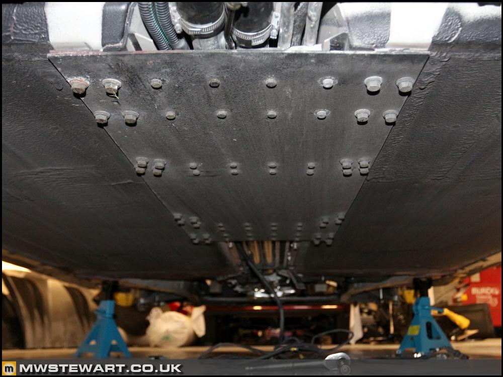
This is the thing with low volume "supercars" like Ferraris, for every lovely CNC machined or exotic carbon part, there is another that is a right old bodge! That plate ^^^ is in the later category, and looks like they found it in a ship yard..... ;-)Smitters said:
JakeT said:
Haven't checked in on this for a while. Still dumbfounded by the amount of work put into this thing. What amazes me more is that you don't work in the automotive industry yet have the inherent knowledge (and testicle size) to pull a Ferrari apart.
From the warm, secure and distant comfort of my keyboard, I can say "it's just nuts and bolts..." but yeah. As I can attest, fists of ham and mechanic-ing do not match. It's a skill for sure. Or maybe the skill is knowing what you can't do, and having a crack at everything else?
Max_Torque said:
This is the thing with low volume "supercars" like Ferraris, for every lovely CNC machined or exotic carbon part, there is another that is a right old bodge! That plate ^^^ is in the later category, and looks like they found it in a ship yard..... ;-)
Haha - it's like a British WW2 tank. I'm going to replace it with a 4mm sheet of quasi-isotropic carbon.Super Slo Mo said:
^^^ Pretty much sums up my thoughts too. Obviously it's functional, but it looks like the bolt holes were drilled by eye. It looks like I made it!
They are all equal but there are some interesting patterns Scuderia ABS loom installation
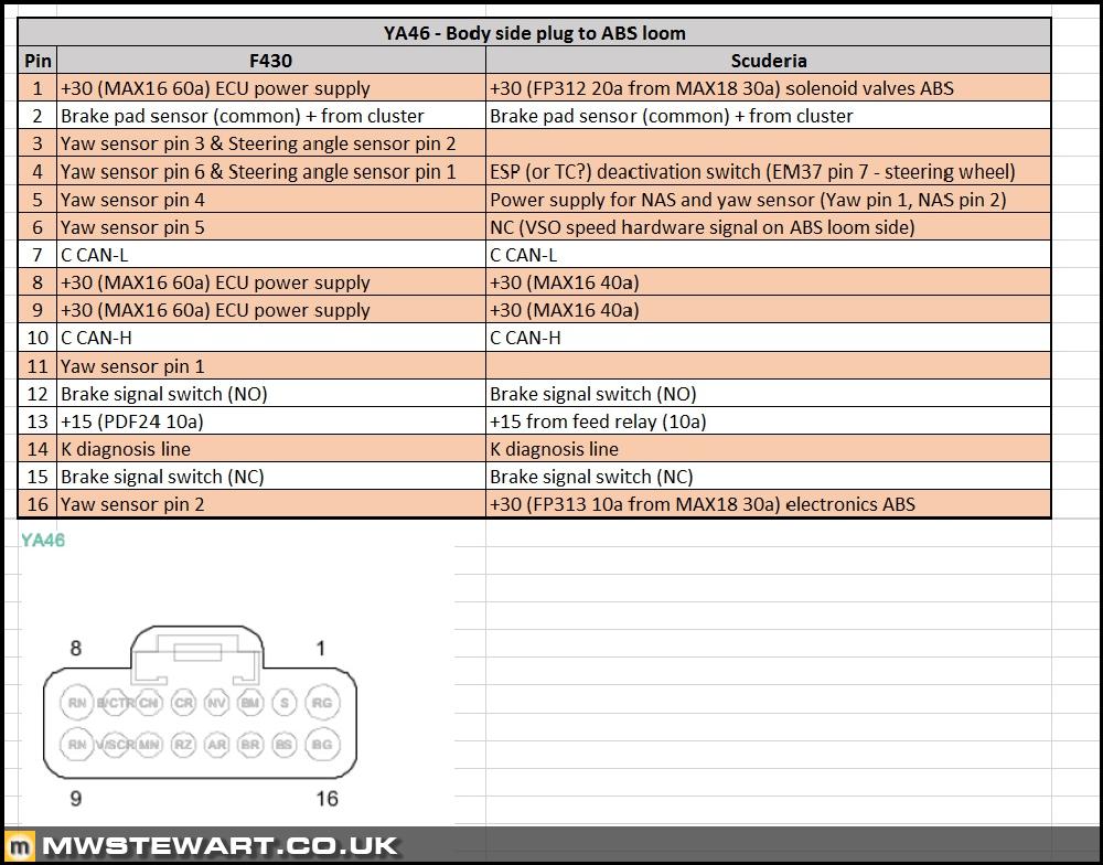
Today I moved on to installation of the Scuderia ABS loom and conversion of my car interface wiring to Scuderia spec. I had prepared by creating spreadsheets detailing the required changes.

Here's a recap of the changes: essentially removing the old yaw sensor wires, adding another power feed, and the 'CT Off' wire through to the instrument cluster. All plugs on the car appear to be made by Delphi; they are easy enough to work on.
I noticed that protection on the bulkhead loom was very minimal and a lot of the old loom tape had fallen off, and this really wasn't ideal in an area of the car where the loom was in direct contact with the body and also subject to water.

Here's plug YA46 stripped down showing the F430 yaw sensor wires ready to be stripped out. I've actually reinserted the old pins and weather seals minus the cable then covered with Tiger Seal - better safe than sorry when it comes to water ingress on essential circuits.

I'm reusing the original pins for the two new wires 'CT Off' and additional power feed. I do this by grinding off the top of the crimp using a Dremel which allows the old wire to be withdrawn, then I rebuild and solder on the requisite wire colours for Scuderia spec.

Finished article.

With the front body loom wiring completed I trued to installing the ABS loom, and so far I've finished the bulkhead and two front wheels; I'm refitting using stainless fastenings and clips.

Here's the business end of the Scuderia ABS loom fitted and my restoration of the existing body loom complete; I cleaned out the area and removed any old tape then applied a liberal covering of Coroplast tape.

Scuttle panel refurbishment
Dad has been helping me today and has started to refurbish the removable trim and scuttle panel itself; an exposed area near the central wiper spigot was showing some light corrosion. The affected area has been taken back to bare metal and then etch primed.

The removable scuttle trim has been treated to the same process.


Scuderia centre console
Today I was contacted from Italy by a very helpful reader of this thread who is embarking on an F430 project, and he wondered if I wanted to swap my LHD centre console for a RHD version. The RHD version is so hard to find I had compromised on the LHD. New is around £2.5k plus VAT so not worth it given I still have more important things to finish.
Here is my LHD console.
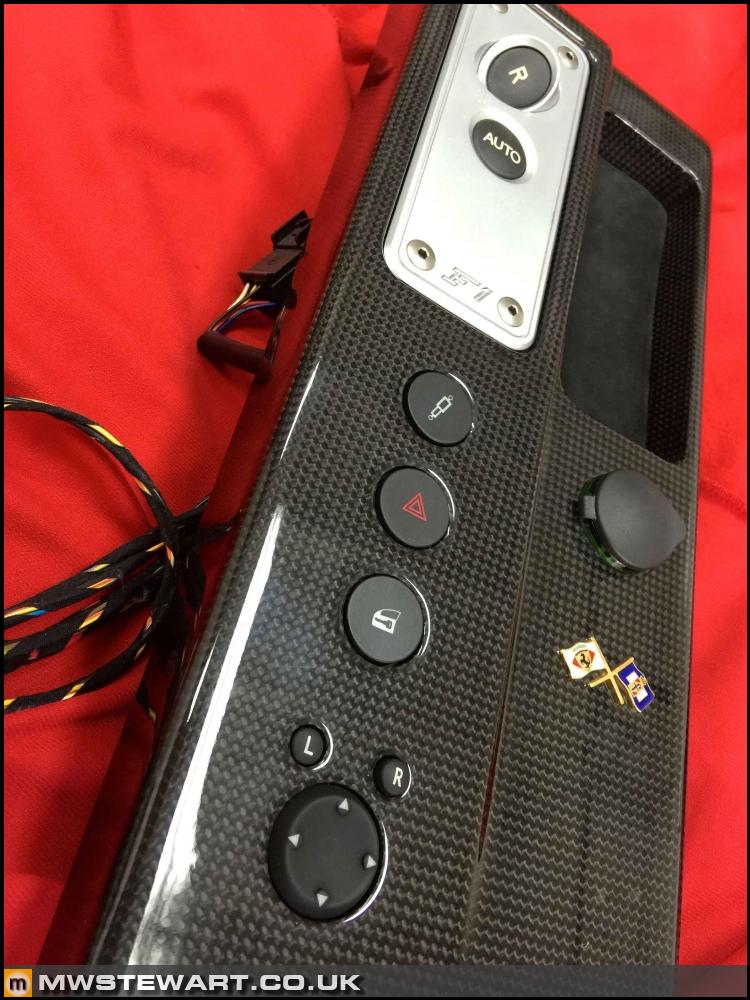
Compare to a RHD car: although the buttons remain in the same position the 'ramp' and F1 panel is on the drivers side.

I've also been advised of some of the factories Ferrari use for interior trim, carbon, and pointed in the direction of a business selling a very interesting weight saving part. More to follow.
Today I moved on to installation of the Scuderia ABS loom and conversion of my car interface wiring to Scuderia spec. I had prepared by creating spreadsheets detailing the required changes.
Here's a recap of the changes: essentially removing the old yaw sensor wires, adding another power feed, and the 'CT Off' wire through to the instrument cluster. All plugs on the car appear to be made by Delphi; they are easy enough to work on.
I noticed that protection on the bulkhead loom was very minimal and a lot of the old loom tape had fallen off, and this really wasn't ideal in an area of the car where the loom was in direct contact with the body and also subject to water.
Here's plug YA46 stripped down showing the F430 yaw sensor wires ready to be stripped out. I've actually reinserted the old pins and weather seals minus the cable then covered with Tiger Seal - better safe than sorry when it comes to water ingress on essential circuits.
I'm reusing the original pins for the two new wires 'CT Off' and additional power feed. I do this by grinding off the top of the crimp using a Dremel which allows the old wire to be withdrawn, then I rebuild and solder on the requisite wire colours for Scuderia spec.
Finished article.
With the front body loom wiring completed I trued to installing the ABS loom, and so far I've finished the bulkhead and two front wheels; I'm refitting using stainless fastenings and clips.
Here's the business end of the Scuderia ABS loom fitted and my restoration of the existing body loom complete; I cleaned out the area and removed any old tape then applied a liberal covering of Coroplast tape.
Scuttle panel refurbishment
Dad has been helping me today and has started to refurbish the removable trim and scuttle panel itself; an exposed area near the central wiper spigot was showing some light corrosion. The affected area has been taken back to bare metal and then etch primed.
The removable scuttle trim has been treated to the same process.
Scuderia centre console
Today I was contacted from Italy by a very helpful reader of this thread who is embarking on an F430 project, and he wondered if I wanted to swap my LHD centre console for a RHD version. The RHD version is so hard to find I had compromised on the LHD. New is around £2.5k plus VAT so not worth it given I still have more important things to finish.
Here is my LHD console.
Compare to a RHD car: although the buttons remain in the same position the 'ramp' and F1 panel is on the drivers side.
I've also been advised of some of the factories Ferrari use for interior trim, carbon, and pointed in the direction of a business selling a very interesting weight saving part. More to follow.
Nezquick said:
This whole thread is utterly fascinating. Awesome work OP. I just don't know where you get all the info you need!!
Next project, buy a Scuderia and Turn it back into a normal F430 with all the parts you have.
lol - that would be funny. Information is not readily available. Ferrari absolutely do not want these cars serviced outside of their network and do everything possible to make it very difficult to do so.Next project, buy a Scuderia and Turn it back into a normal F430 with all the parts you have.
I had to pay through the nose for some of the technical information - and go to the Far East to get it!


mwstewart said:
Max_Torque said:
This is the thing with low volume "supercars" like Ferraris, for every lovely CNC machined or exotic carbon part, there is another that is a right old bodge! That plate ^^^ is in the later category, and looks like they found it in a ship yard..... ;-)
Haha - it's like a British WW2 tank. I'm going to replace it with a 4mm sheet of quasi-isotropic carbon.Super Slo Mo said:
^^^ Pretty much sums up my thoughts too. Obviously it's functional, but it looks like the bolt holes were drilled by eye. It looks like I made it!
They are all equal but there are some interesting patterns Anyway, regarding the big metal plate above, the size, thickness and number of bolts suggests to me that it's significantly structural in some way, so I would be careful about replacing it with something more aesthetically pleasing. The same probably applies to replacing the bolts with cap headed ones.
Super Slo Mo said:
All joking aside, it's a stunning car, I am insanely jealous, and inspired to work hard to be in a position to be able to afford one myself.
Anyway, regarding the big metal plate above, the size, thickness and number of bolts suggests to me that it's significantly structural in some way, so I would be careful about replacing it with something more aesthetically pleasing. The same probably applies to replacing the bolts with cap headed ones.
It will have been researched, analysed, a spread sheet used, lightened, improved and strengthened. And perhaps shinier. Anyway, regarding the big metal plate above, the size, thickness and number of bolts suggests to me that it's significantly structural in some way, so I would be careful about replacing it with something more aesthetically pleasing. The same probably applies to replacing the bolts with cap headed ones.
My name is snobetter, I'm a MW disciple...
Thanks guys. I do consider myself extremely fortunate to have the car. This is basically a dream project for me.
I'm not replacing the sheet for aesthetics but for lightness. The standard ali part is 3mm thick and 4.3kg whereas quasi-isotropic sheet in the same thickness is 11.3x stronger, 2.0x stiffer, and at 2.6kg almost half the weight. Speedwerks in the states have done all the R&D on the approach http://www.speed-werks.com/ferrari-undertray
Small changes but as I've found with this project - they all add up.

Taken from https://dragonplate.com/
I say the fastenings are ugly but from a drag perspective not aesthetic, although arguable they are that too! The two rows of M10 bolts secure the plate to the car and there are lots of them to ensure high clamping load across the body contact patch in order to maximise torsional rigidity of the assembly. The application doesn't call for high tensile fastenings.
I'm not replacing the sheet for aesthetics but for lightness. The standard ali part is 3mm thick and 4.3kg whereas quasi-isotropic sheet in the same thickness is 11.3x stronger, 2.0x stiffer, and at 2.6kg almost half the weight. Speedwerks in the states have done all the R&D on the approach http://www.speed-werks.com/ferrari-undertray
Small changes but as I've found with this project - they all add up.
Taken from https://dragonplate.com/
I say the fastenings are ugly but from a drag perspective not aesthetic, although arguable they are that too! The two rows of M10 bolts secure the plate to the car and there are lots of them to ensure high clamping load across the body contact patch in order to maximise torsional rigidity of the assembly. The application doesn't call for high tensile fastenings.


Max_Torque said:
Be careful solderig wires into crimp contacts! Use as LITTLE solder as you can, otherwise it wicks backwards up the wire, past the insulation support, and results in a brittle fracture at that point in a very short time indeed!
This in spades, we never use anything else but crimped connections in signalling that I used to work with. You may also want to ensure the flux is completely removed.Thanks gents that's good advice. It can also stray into the pin itself and cause assembly or connection issues. I've learnt both issues the hard way - nothing worse than a kink in the cable outboard of the housing. I've ended up fairly deft at these deconstruction techniques over the years but getting a stock of OEM housings and pins would be good.
The Scuderia ABS loom is now installed though I didn't take any photos of it as that would be even less interesting as dissembled connectors  I also on the interior wiring and after exposing the tunnel wiring - which is essentially the spine of the car linking front and rear - it hit me: why am I leaving the heated and electric seat wiring in place? At the moment I have a pair of defunct multi plugs under each seat and the wiring is heavy gauge i.e. heavy.
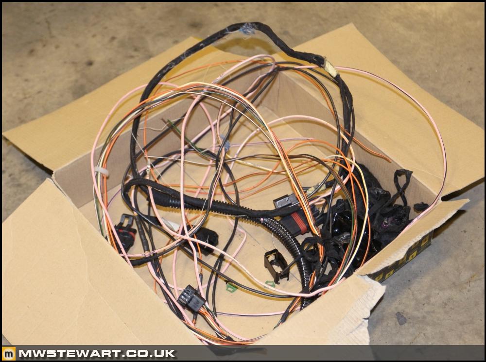

The F430 loom is almost completely modular, which is quite interesting. I've stripped out the seat looms as far as one of the main connectors including the pins and will continue tomorrow by removing the rest right up to the fuse and relay boxes.

I made a start on removing removed the old yaw sensor wiring but have a few cut wires at convenient points that I need to trace back to source. There's already a reasonable amount of weight in the superfluous loom I've removed.
When wiring up the new yaw sensor I made use of a spare connector I'd purchased for practice disassembly. This one's an AMP housing that uses the fairly ubiquitous small pins with a triangular locking tang.
Here is the new yaw sensor installed with the correct factory colours. I cut some Coroplast in half width ways to replicate the small tape used by Ferrari on smaller parts of the loom. I drew around the old yaw sensor with a pencil so I had an outline to align the new one so at least the starting point was somewhere near. I will investigate zero point calibration of the yaw rate and acceleration sensor once the car is running.

It felt lighter. I had to weigh it out of interest.


I also on the interior wiring and after exposing the tunnel wiring - which is essentially the spine of the car linking front and rear - it hit me: why am I leaving the heated and electric seat wiring in place? At the moment I have a pair of defunct multi plugs under each seat and the wiring is heavy gauge i.e. heavy.The F430 loom is almost completely modular, which is quite interesting. I've stripped out the seat looms as far as one of the main connectors including the pins and will continue tomorrow by removing the rest right up to the fuse and relay boxes.
I made a start on removing removed the old yaw sensor wiring but have a few cut wires at convenient points that I need to trace back to source. There's already a reasonable amount of weight in the superfluous loom I've removed.
When wiring up the new yaw sensor I made use of a spare connector I'd purchased for practice disassembly. This one's an AMP housing that uses the fairly ubiquitous small pins with a triangular locking tang.
Here is the new yaw sensor installed with the correct factory colours. I cut some Coroplast in half width ways to replicate the small tape used by Ferrari on smaller parts of the loom. I drew around the old yaw sensor with a pencil so I had an outline to align the new one so at least the starting point was somewhere near. I will investigate zero point calibration of the yaw rate and acceleration sensor once the car is running.
It felt lighter. I had to weigh it out of interest.
Today I finished the yaw sensor wiring which involved running the earth and power feeds to the front of the car where they tie into the steering angle sensor.
I also turned my attention to removing the remaining seat looms. I don't know which wires are heating and which are power adjustment because my diagrams don't cover it, but one circuit goes to one of the front fuse boxes so I started there removing the switched side of the loom.

Each seat has a separate 30 amp Maxi fuse which I removed along with its terminal. The power supply was from a common bus bar so nothing further to strip out on the power side.

Fuse box assembled and loom wrapped up with the original sheath.

The second pair of seat circuits ran to the back of the car where there are two further fuse/relay boards.

I traced the seat wires to the RH side of the car and removed the terminal and a purple relay.

This particular circuit had a dedicated power feed so to really optimise the weight of the body loom I decided to trace it to source and remove it. This took me over to the LH side of the car.

The power feed was via a 30amp Maxi from main bus bar, so I removed the fuse and terminals. I would like to fit La Ferrari brakes somewhere down the line so this spare power feed fuse slot will come in handy for the electric handbrake.

The heated seats have a feed into the instrument cluster - or what Ferrari calls the control panel, because that's in effect what it is - to trigger the indication lamp, so I stripped that out. The liberated pin was quite essential because it allowed me to wire in the bumpy road button to connector C.

Loom wrapped up with bumpy road button wiring complete.

I estimate there's a day of work left before I can test the ABS, Scuderia instrument cluster, and bumpy road button.
I also turned my attention to removing the remaining seat looms. I don't know which wires are heating and which are power adjustment because my diagrams don't cover it, but one circuit goes to one of the front fuse boxes so I started there removing the switched side of the loom.
Each seat has a separate 30 amp Maxi fuse which I removed along with its terminal. The power supply was from a common bus bar so nothing further to strip out on the power side.
Fuse box assembled and loom wrapped up with the original sheath.
The second pair of seat circuits ran to the back of the car where there are two further fuse/relay boards.
I traced the seat wires to the RH side of the car and removed the terminal and a purple relay.
This particular circuit had a dedicated power feed so to really optimise the weight of the body loom I decided to trace it to source and remove it. This took me over to the LH side of the car.
The power feed was via a 30amp Maxi from main bus bar, so I removed the fuse and terminals. I would like to fit La Ferrari brakes somewhere down the line so this spare power feed fuse slot will come in handy for the electric handbrake.
The heated seats have a feed into the instrument cluster - or what Ferrari calls the control panel, because that's in effect what it is - to trigger the indication lamp, so I stripped that out. The liberated pin was quite essential because it allowed me to wire in the bumpy road button to connector C.
Loom wrapped up with bumpy road button wiring complete.
I estimate there's a day of work left before I can test the ABS, Scuderia instrument cluster, and bumpy road button.
Gassing Station | Readers' Cars | Top of Page | What's New | My Stuff