Discussion


mwstewart said:
Interesting. The cam chain sprokets look to be quite worn too.
Quite possibly. I didn't pay too much attention as I quickly realised that we weren't dealing with the internals of a volkswagen or Mercedes, so knew they had to go.Still have them if any loyal die hards want them

I'm used to looking at C30SE (Opel Straight six) Cam setups and they are single chain and prone to lubrication shortfall - the sprockets are normally way better than the ones in that six banger
What's the parts availability like for the parts - I'm guessing better than my favorite Opel Engine
What's the parts availability like for the parts - I'm guessing better than my favorite Opel Engine
B'stard Child said:
I'm used to looking at C30SE (Opel Straight six) Cam setups and they are single chain and prone to lubrication shortfall - the sprockets are normally way better than the ones in that six banger
What's the parts availability like for the parts - I'm guessing better than my favorite Opel Engine
To be honest I'm not sure what the availability of the original stuff is as I decided it wouldn't be going back, but Id guess one o the big players would have the relevant bits.What's the parts availability like for the parts - I'm guessing better than my favorite Opel Engine
Some lubrication mods will be coming up when I get the next batch of pics up

And ultimately Im aiming for at least 100bhp per a litre normally aspirated
Edited by m4tti on Monday 6th October 23:20
Edited by m4tti on Monday 6th October 23:20
Mark Benson said:
Agreed.
Also, 4. OP is writing a detailed, informative account of what he's doing.
Looking forward to further instalments.
Thanks all who have posted an interest. This is a warts and all type build. Hopefully the honesty and the ultimate decisions made, won't upset too many speed six purists..Also, 4. OP is writing a detailed, informative account of what he's doing.
Looking forward to further instalments.
Edited by m4tti on Tuesday 7th October 00:17
Edited by m4tti on Tuesday 7th October 13:24

Back to it..
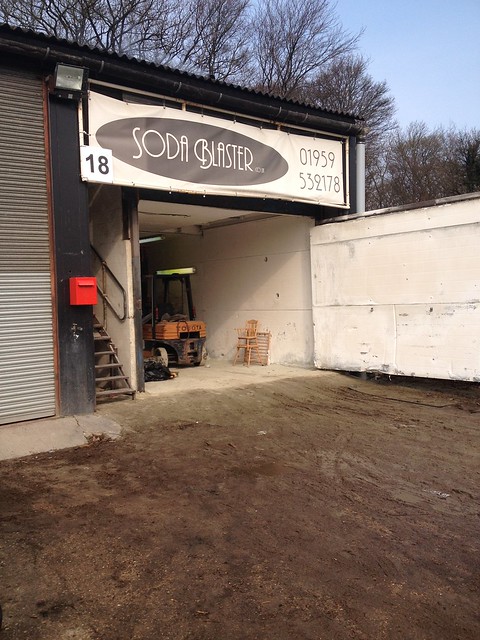
I decided I wanted the engine to look like new when it went back in the car , so literally every single thing was removed from the block so it could be soda blasted before it was relined. The block and all other ancillaries were taken to Soda Blaster in Knockholt.
 IMG_1032 by Barkley Dogue, on Flickr
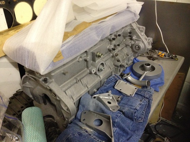
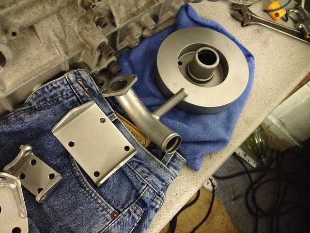
They did a great job cleaning all of the metal parts I took them including the block, water pipes, engine mount brackets and damper. While they were at it they did me a good deal on powder coating, so I had all of my newly blasted metal parts powder coated. After a week or so I had a call saying everything was ready, so as part of the big team effort, my mum duly went and collected all the parts and dropped them off to me after work one evening. Everything looked great.
I did try power washing the block with Gunk, but it was fairly useless.
 DSC_0156 by Barkley Dogue, on Flickr
Thats better.. parts on bench
 [url=https:
//flic.kr/p/pCM2SD]IMG_1047[/url] by Barkley Dogue, on Flickr
 IMG_1046 by Barkley Dogue, on Flickr
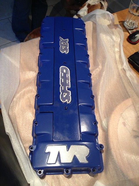
Cam cover prior to polishing..
 IMG_1045 by Barkley Dogue, on Flickr
I took several days off the following week in order to get a few more bits done and take the block up to racing green to leave it with them to have it relined.
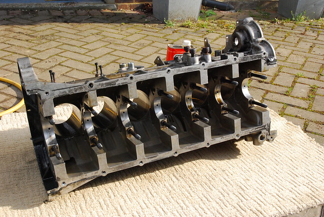
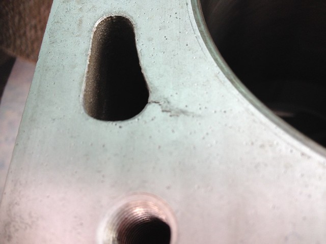
Disaster!!… upon pressure washing the soda from the block I noticed some black dirt in a line from the corner of the water jackets. I tried scraping the black dirt from the block, but to my horror this wasn’t black dirt.. it was a cracked block!! Son of Jorel, what ever next. There was also a reasonable amount of porosity.
 IMG_1049 by Barkley Dogue, on Flickr
Strangely the car never once over heated in my hands. You never know though what your going to get when you open a TVR engine up.
I took the block to Racing green where we reviewed the options. The cracks could be ground out and tig welded back up, but in the end (with my ultimate aim) I decided to take a refurbed block, obviously an unforeseen cost. Mildy stressing.
Racing Green, had the block relined. The engineering partner they use for this does more than simply pressing the liners in, they will heat the block, press the liners, cool the block then measure the height of the liners, then measure once again when the block has been left overnight.
It took a little while for the work on the block and for the head to be completed, so this gave me time for a couple of other important supporting activities.
Engine Work
Whilst the block was being relined I had all of the supporting build components supplied, rods, pistons, clutch cover, light weight flywheel etc. I took all of these components on a visit to Julian Godfrey Engineering to have the bottom end balanced and the crank polished.
Julian Godfrey came with a decent reputation and strong background in motorsport and big power engines builds, most notably the pikes peak Monster Energy RS200!

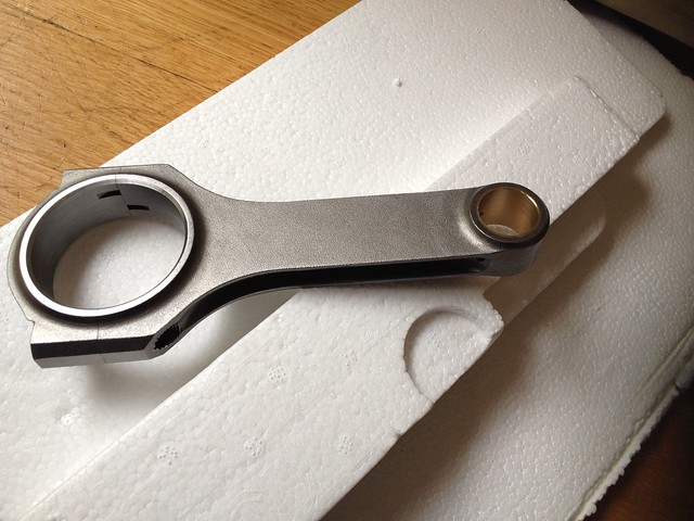
The rods as you can see were a big step up in terms of quality over the standard items, which have had documented failures. The quality of production was also evident in the fact that all of the rods weighed within <1gram of each other. The pistons were also all within 1 gram of each other.
New rods..
 IMG_1072 by Barkley Dogue, on Flickr
Old Rods.... not nice.
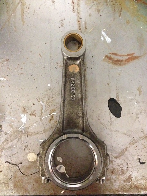 IMG_1506 by Barkley Dogue, on Flickr
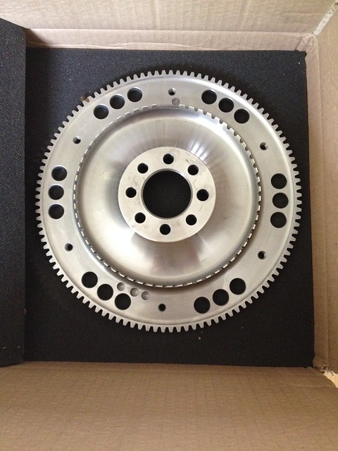
Should go nicely with the lighweight flywheel..
 IMG_1071 by Barkley Dogue, on Flickr
The above and all of the other necessary parts were left at Julian Godfrey for several weeks, whilst the balancing and the crank polish was completed. A nice chap called Ray received the parts and went through what I wanted done and gave me a tour of the work shop and the machines used in the process, which was most appreciated.
In addition to the balancing and polishing I got the guys at JG to measure the crank journals and determine whether they were out of round, they came back and said everything was round. This gave some reassurance to the plastigauge readings I had taken as the risk with plastiguage is that the crank is out of round so on the top side of journal you could be in spec but other points could wander out.
On top of all that the price for the work wasn't too outrageous!
Engine bay
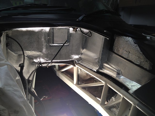
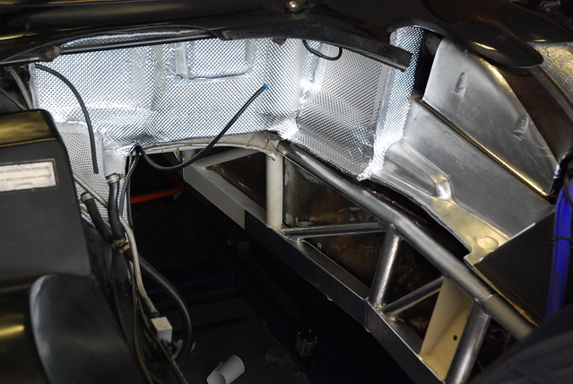
The remainder of the time I had whilst the block work was carried out set about refurbing the engine bay . Both the chassis and the heat shielding material were in a bit of a sorry state. Not awful but could definitely do with a refresh.
 IMG_1125 by Barkley Dogue, on Flickr
 IMG_1123 by Barkley Dogue, on Flickr
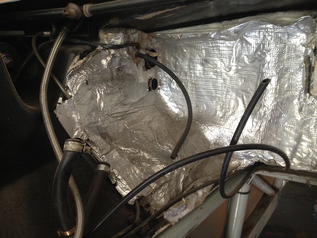
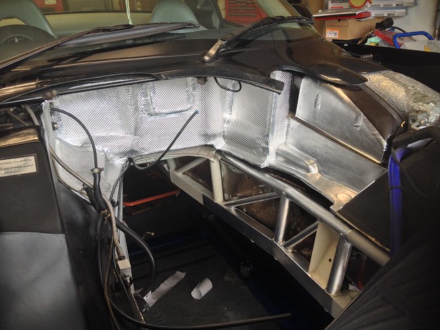
The factory heat shielding was fairly low quality. It predominantly consisted of fibre glass backed baco foil, with complex surfaces heavily taped over to form the shape. It looked fairly rough and delivered that fibreglass itch when touch. In places near the exhaust manifold it had simply disintegrated and was allowing the raw fibre glass to be exposed to the heat.
After ringing round several places I spoke with Nimbus motosport. I spoke to a chap called Chris who was very patient with me, sending out numerous samples of the products they sell, to help me make my decision. Youd think it was easy, but originally I wanted to use gold sheet, but Chris persuaded me otherwise as it would offer no sound proofing from the engine bay and wouldnt be as durable as the shielding I ultimately went for.
After going through a few samples (All sent out free of charge) a role of DEI floor and tunnel was supplied for the bulkhead and DEI reflect –a-Kool for the chassis and under bonnet areas which were directly exposed to the heat the exhaust manifolds these engines put out ..and they do run typically run hot.
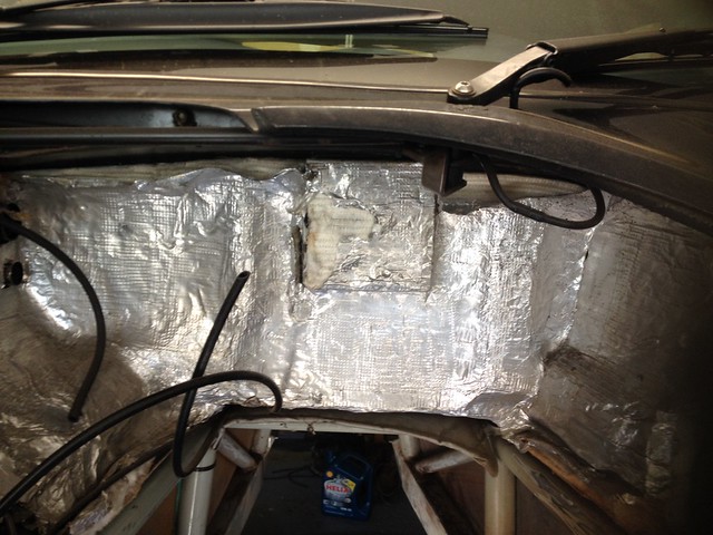
It’s a tedious job, remove the old heat shielding dropping bits of spikey glass fibre, scrubbing the old adhesive off and preparing the bulk head surface, creating templates from the old heat shielding, then cutting out the new panels. I put the new panels in place and secured them with a wall paper roller.
 IMG_1167 by Barkley Dogue, on Flickr
 IMG_1161 by Barkley Dogue, on Flickr
 DSC_0160 by Barkley Dogue, on Flickr
I decided I wanted the engine to look like new when it went back in the car , so literally every single thing was removed from the block so it could be soda blasted before it was relined. The block and all other ancillaries were taken to Soda Blaster in Knockholt.
IMG_1032 by Barkley Dogue, on FlickrThey did a great job cleaning all of the metal parts I took them including the block, water pipes, engine mount brackets and damper. While they were at it they did me a good deal on powder coating, so I had all of my newly blasted metal parts powder coated. After a week or so I had a call saying everything was ready, so as part of the big team effort, my mum duly went and collected all the parts and dropped them off to me after work one evening. Everything looked great.
I did try power washing the block with Gunk, but it was fairly useless.
DSC_0156 by Barkley Dogue, on FlickrThats better.. parts on bench
[url=https://flic.kr/p/pCM2SD]IMG_1047[/url] by Barkley Dogue, on Flickr
IMG_1046 by Barkley Dogue, on FlickrCam cover prior to polishing..
IMG_1045 by Barkley Dogue, on FlickrI took several days off the following week in order to get a few more bits done and take the block up to racing green to leave it with them to have it relined.
Disaster!!… upon pressure washing the soda from the block I noticed some black dirt in a line from the corner of the water jackets. I tried scraping the black dirt from the block, but to my horror this wasn’t black dirt.. it was a cracked block!! Son of Jorel, what ever next. There was also a reasonable amount of porosity.
IMG_1049 by Barkley Dogue, on FlickrStrangely the car never once over heated in my hands. You never know though what your going to get when you open a TVR engine up.
I took the block to Racing green where we reviewed the options. The cracks could be ground out and tig welded back up, but in the end (with my ultimate aim) I decided to take a refurbed block, obviously an unforeseen cost. Mildy stressing.
Racing Green, had the block relined. The engineering partner they use for this does more than simply pressing the liners in, they will heat the block, press the liners, cool the block then measure the height of the liners, then measure once again when the block has been left overnight.
It took a little while for the work on the block and for the head to be completed, so this gave me time for a couple of other important supporting activities.
Engine Work
Whilst the block was being relined I had all of the supporting build components supplied, rods, pistons, clutch cover, light weight flywheel etc. I took all of these components on a visit to Julian Godfrey Engineering to have the bottom end balanced and the crank polished.
Julian Godfrey came with a decent reputation and strong background in motorsport and big power engines builds, most notably the pikes peak Monster Energy RS200!
The rods as you can see were a big step up in terms of quality over the standard items, which have had documented failures. The quality of production was also evident in the fact that all of the rods weighed within <1gram of each other. The pistons were also all within 1 gram of each other.
New rods..
IMG_1072 by Barkley Dogue, on FlickrOld Rods.... not nice.
IMG_1506 by Barkley Dogue, on FlickrShould go nicely with the lighweight flywheel..
IMG_1071 by Barkley Dogue, on FlickrThe above and all of the other necessary parts were left at Julian Godfrey for several weeks, whilst the balancing and the crank polish was completed. A nice chap called Ray received the parts and went through what I wanted done and gave me a tour of the work shop and the machines used in the process, which was most appreciated.
In addition to the balancing and polishing I got the guys at JG to measure the crank journals and determine whether they were out of round, they came back and said everything was round. This gave some reassurance to the plastigauge readings I had taken as the risk with plastiguage is that the crank is out of round so on the top side of journal you could be in spec but other points could wander out.
On top of all that the price for the work wasn't too outrageous!
Engine bay
The remainder of the time I had whilst the block work was carried out set about refurbing the engine bay . Both the chassis and the heat shielding material were in a bit of a sorry state. Not awful but could definitely do with a refresh.
IMG_1125 by Barkley Dogue, on FlickrIMG_1123 by Barkley Dogue, on FlickrThe factory heat shielding was fairly low quality. It predominantly consisted of fibre glass backed baco foil, with complex surfaces heavily taped over to form the shape. It looked fairly rough and delivered that fibreglass itch when touch. In places near the exhaust manifold it had simply disintegrated and was allowing the raw fibre glass to be exposed to the heat.
After ringing round several places I spoke with Nimbus motosport. I spoke to a chap called Chris who was very patient with me, sending out numerous samples of the products they sell, to help me make my decision. Youd think it was easy, but originally I wanted to use gold sheet, but Chris persuaded me otherwise as it would offer no sound proofing from the engine bay and wouldnt be as durable as the shielding I ultimately went for.
After going through a few samples (All sent out free of charge) a role of DEI floor and tunnel was supplied for the bulkhead and DEI reflect –a-Kool for the chassis and under bonnet areas which were directly exposed to the heat the exhaust manifolds these engines put out ..and they do run typically run hot.
It’s a tedious job, remove the old heat shielding dropping bits of spikey glass fibre, scrubbing the old adhesive off and preparing the bulk head surface, creating templates from the old heat shielding, then cutting out the new panels. I put the new panels in place and secured them with a wall paper roller.
IMG_1167 by Barkley Dogue, on FlickrIMG_1161 by Barkley Dogue, on FlickrDSC_0160 by Barkley Dogue, on FlickrEdited by m4tti on Monday 13th October 11:50
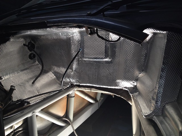
Hi Rob, the sequence is a bit arse about face, I'll put up what I did with the chassis shortly. The silver on the chassis rail you can see is the Reflect -a-kool heat shield.
Hope the head gasket is going well. Good time to swap your heat shielding
Hope the head gasket is going well. Good time to swap your heat shielding
Edited by m4tti on Sunday 12th October 19:37
It looks great Matt. Last time I was in this position, I used the Nimbus Motorsport stuff to protect those rails, but that looks really good. Head gasket is slow progress, in actual fact so slow that Track V Road are finishing the job off for me! The bulkhead heatshield looks great, but what a mess TVR made in the first place!
m4tti said:
Is that a TTV one - has all the hallmarks of one of theirsI have one ready for my 3.7 Opel 6 banger - it's never going to touch a TVR lump for BHP but what can I say I'm a sucker for old opels
Honestly I have no idea. This was supplied as-is by racing green. A number of their parts suppliers are a closely guarded secret. Although I can say the one supplier I know of is ferrari OEM, hence I had confidence in them as the standout parts supplier in the TVR game, so used them exclusively.
m4tti said:
Honestly I have no idea. This was supplied as-is by racing green. A number of their parts suppliers are a closely guarded secret. Although I can say the one supplier I know of is ferrari OEM, hence I had confidence in them as the standout parts supplier in the TVR game, so used them exclusively.
I'd put a couple of quid on it being a TTV oneThis is mine (simple but silly light - hybrid to fit Lotus Carlton Crank using a Monza GSE friction plate and an Audi S3 pressure plate - I'm not afraid to use non opel stuff)

And this is one they did for a friends car needed an extra for a crank sensor

Edited by B'stard Child on Monday 13th October 00:05
m4tti said:
Yeah the original heat shielding really is poor. This stuff should lift it up closer to modern production standards.
I understand about letting TvR finish it. It can really drag and drag and you just want it done!
Best of luck with it, the Speed Six is a wonderful engine. I absolutely adored my old Tuscan, it just didn't have that special "something" that I find present in a Cerbera. Loved the experience though.I understand about letting TvR finish it. It can really drag and drag and you just want it done!
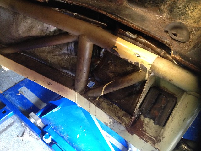
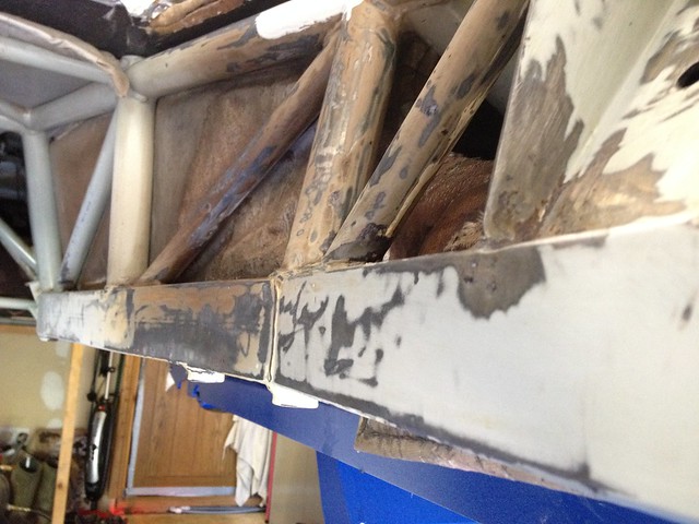
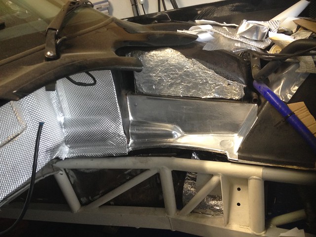
Whilst the engine bay was empty I also cleaned the chassis up. I wire brushed any signs of rust and repainted the majority of the area with KBS Rust seal. The chassis areas closest to the Exhaust manifolds got a coating of KBS Extreme heat before receiving the reflective layer. To top the chassis and match the original colour I mixed white and black Hammerite, which was rollered on and looked just as good as the original coating. Things were starting to take on a fresh appearance.
Heat damaged chassis coating next to cats.. It looked a bit grisly where someone had splodged some paint over the cracked chassis coating. You can see where the heat is so severe in that area that the engine mount has crumbled to nothing.
 IMG_1095 by Barkley Dogue, on Flickr
Flaking coating and rust ground back -
 IMG_1127 by Barkley Dogue, on Flickr
A rust removal solution KBS Rust Blast was applied to the area which would etch it with a zinc coating.
High temp paint applied..
 IMG_1150 by Barkley Dogue, on Flickr
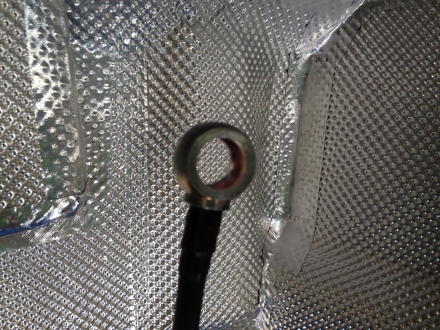
Finally I applied the heat reflective material to the area just to make sure..
 IMG_1179 by Barkley Dogue, on Flickr
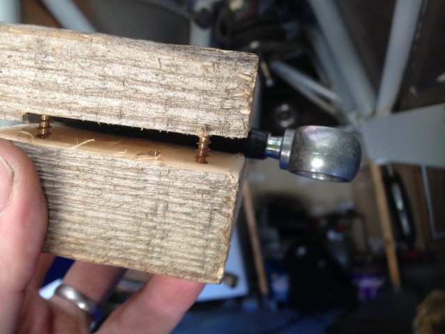
The last thing I had left to do in the engine bay was to re-install the banjo into the rigid fuel line which I foolishly cut off when removing the engine. At the time I removed the engine I couldn’t get the rear banjo bolt to budge and was nervous about damaging the rail and the throttle bodies it mounted on to. I should have persisted and re-fitting that banjo into the rigid nylon fuel line in-situ was a b*tch and. I had make a clamp to support the hose to stop it from kinking. Even when heated the banjo needed some serious oomph to go back in. It would only o back in a couple of mm at a time, otherwise the hose would kink. Each mm, involved heating it in a cup of boiling water and slowly pushing the banjo back in An afternoon spent swearing. Lesson learned, never ever cut that banjo off.
To clamp the hose I took a block of wood and drilled a hole the same diameter as the hose. I then cut the wood in half through the center of the drilled hole.
 IMG_1268 by Barkley Dogue, on Flickr
After many hours it was back in ...
 IMG_1276 by Barkley Dogue, on Flickr
Plus a nice blister for my efforts..
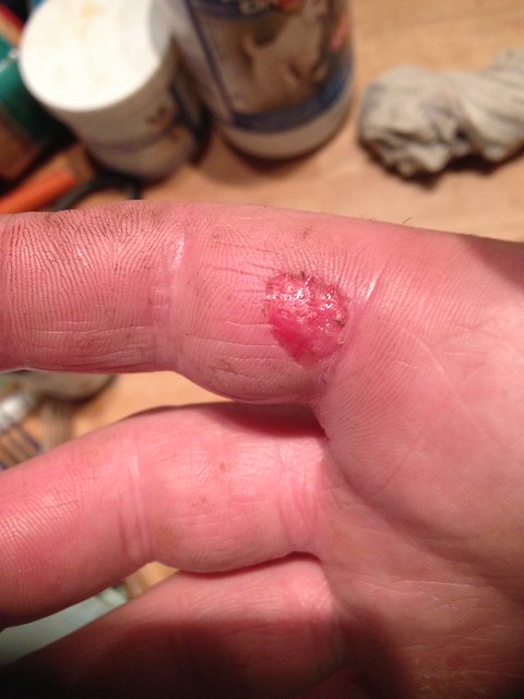 IMG_1278 by Barkley Dogue, on Flickr
I swear the car hated me!
Heat damaged chassis coating next to cats.. It looked a bit grisly where someone had splodged some paint over the cracked chassis coating. You can see where the heat is so severe in that area that the engine mount has crumbled to nothing.
IMG_1095 by Barkley Dogue, on FlickrFlaking coating and rust ground back -
IMG_1127 by Barkley Dogue, on FlickrA rust removal solution KBS Rust Blast was applied to the area which would etch it with a zinc coating.
High temp paint applied..
IMG_1150 by Barkley Dogue, on FlickrFinally I applied the heat reflective material to the area just to make sure..
IMG_1179 by Barkley Dogue, on FlickrThe last thing I had left to do in the engine bay was to re-install the banjo into the rigid fuel line which I foolishly cut off when removing the engine. At the time I removed the engine I couldn’t get the rear banjo bolt to budge and was nervous about damaging the rail and the throttle bodies it mounted on to. I should have persisted and re-fitting that banjo into the rigid nylon fuel line in-situ was a b*tch and. I had make a clamp to support the hose to stop it from kinking. Even when heated the banjo needed some serious oomph to go back in. It would only o back in a couple of mm at a time, otherwise the hose would kink. Each mm, involved heating it in a cup of boiling water and slowly pushing the banjo back in An afternoon spent swearing. Lesson learned, never ever cut that banjo off.
To clamp the hose I took a block of wood and drilled a hole the same diameter as the hose. I then cut the wood in half through the center of the drilled hole.
IMG_1268 by Barkley Dogue, on FlickrAfter many hours it was back in ...
IMG_1276 by Barkley Dogue, on FlickrPlus a nice blister for my efforts..
IMG_1278 by Barkley Dogue, on FlickrI swear the car hated me!
Engine Build
I had a call letting me know the block and head were ready so I made my way up to RG to collect all the necessary parts. I took everything I needed to put the engine together except for the head. This was assembled by RG and it was agreed with them that I would return the bottom end to them for their engine builder “woody” to put on and time up. An initial install of the crank was performed to ensure my crank and the new block were a good match. Luckily they were and I could run with standard bearings and not need any form of adjustment on the crank or main bearings.
Polished crank journals..
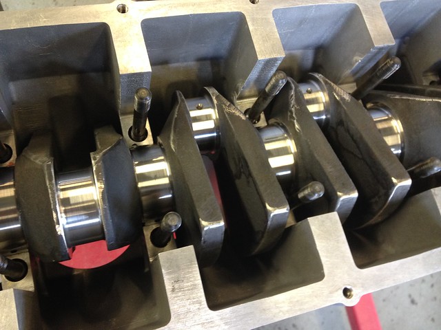 IMG_1218 - Copy by Barkley Dogue, on Flickr
Assembling the bottom end was fairly straight forward. I wont go in to intricate detail as there are loads of decent books and resources out there to guide you through this. One which I found really useful was actually a US Honda tuning site they had a fairly interesting video http://www.evans-tuning.com/tech-videos/how-to-bui...
Before I did the real assembly I did a dry build to establish the pistons height above deck. I measured this with a dti and relayed the figures to RG, and everything was in order.
I bought a tapered ring compressor to install the pistons. Using the tapered ring compressor made installing the pistons incredibly easy. Obtaining one of these in this size in the UK took some doing.. to my knowledge this was the last one left in this country.
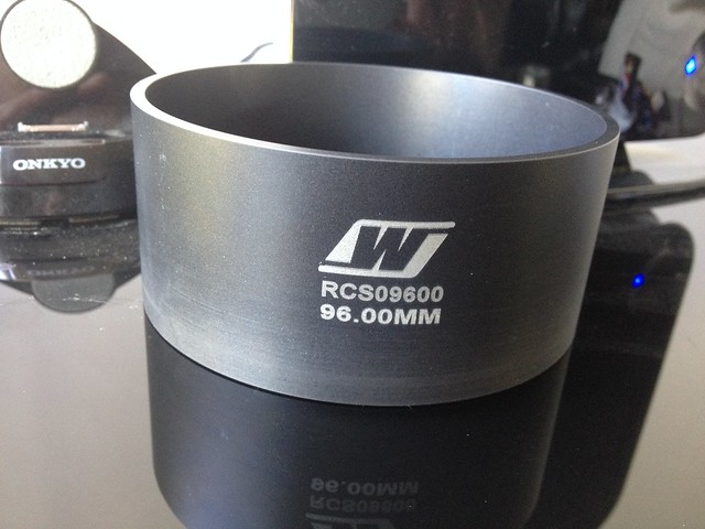 IMG_1171 by Barkley Dogue, on Flickr
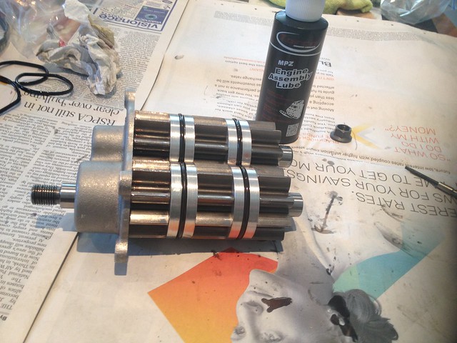
Put piston on rod, put rings on piston, verify ring gaps on piston, align rings, line up ring compressor and simply push in. The pistons could be installed in this way with just finger pressure. I lubricated all gudgeon pins with Toroco engine build lube and coated the cylinders with standard mineral oil.
Pistons, rods, and gudgeon pins ready for assembly..
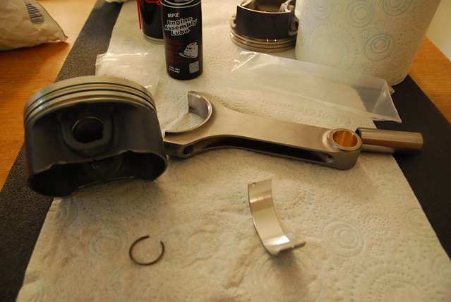 DSC_0180 by Barkley Dogue, on Flickr
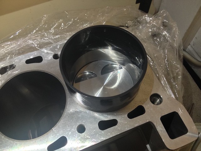
Piston and rod dropped in through tapered ring compressor..
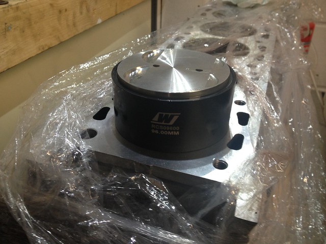 IMG_1247 by Barkley Dogue, on Flickr
Gentle pressure and it starts to locate into the bore...
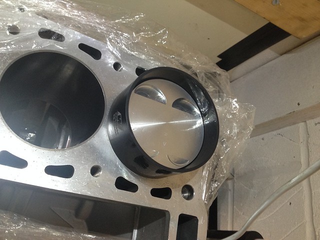 IMG_1248 by Barkley Dogue, on Flickr
And its in..
 IMG_1249 by Barkley Dogue, on Flickr
Taking no chances with dirt, I kept the bottom end heavily wrapped only unwrapping areas I needed access to when required.
Con rod installations was completed using Arp bolts. I’d never assembled the bottom end of an engine before so was fairly nervous considering the total cost of the parts involved, but I think if I had to do it again I’d feel more comfortable. The main thing is to take your time, and double check, and triple check everything, and at all stages make sure the engine feels right. Nothing should be binding. I marked everything as I went indicating it had been torque up as necessary.
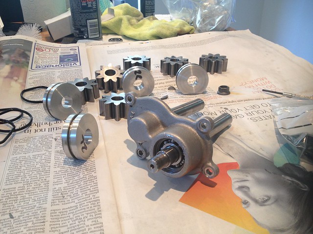
The water pump and high pressure oil pump were rebuilt by RG as some tooling which I didn’t have was required, I could probably have fabricated these my self, but I really wanted to get the car back on the road before the end of summer. I did rebuild the scavenge pump which returns oil from the sump to the dry sump tank.
Scavenge pump..lots of bits..
 IMG_1250 by Barkley Dogue, on Flickr
And back together again.. bearings replaced and all O-rings renewed
 IMG_1251 by Barkley Dogue, on Flickr
Again no rocket science here but it needs a patient logical approach, and thorough inspection of parts.
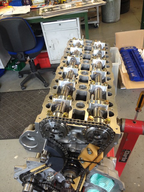
Although I completely understood the principal of timing the engine up with a degree wheel there were zero reference points to use. You essentially use a Degree wheel on the crank to find TDC, and a DTI on number 1 cam to determine the centre line angle. I took the decision in the end to have the head put on and timed up by RG, I had timed up the old engine, but felt more comfortable having it done by someone familiar with the FFF considering its cost and the fact I had to collect it as it required assembly. I couldn't even compare to the reference marks I made on my old head as the timing pf the new head would be somewhat different.
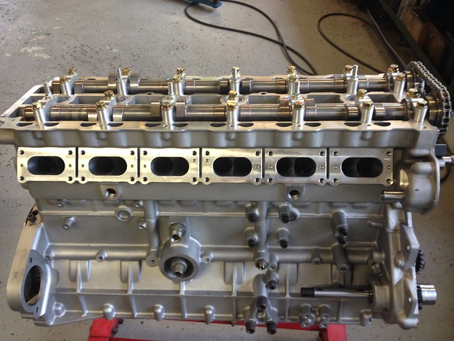
First glimpse of head waiting for assembly..
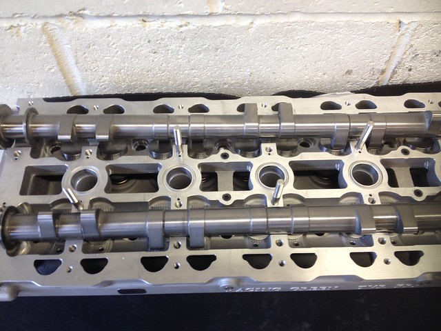 IMG_1227 by Barkley Dogue, on Flickr
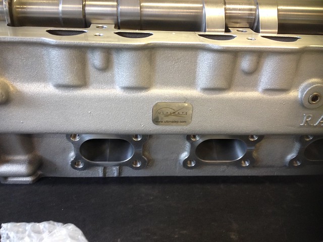 IMG_1223 by Barkley Dogue, on Flickr
It was almost too nice to use
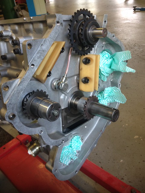
Whilst the head was installed the existing duplex timing gear was replaced with RG’s simplex timing set up. The standard half time shaft of this engine was originally supported by a splash fed bearing, this was replaced by a pressure fed roller bearing. As well as the improved oiling to the bearing the simplex setup dropped a considerable weight from the timing set up, in the region of a kilo. On top of that specification of the simplex chain was more than good enough to offer the same load carrying capabilities to remove the duplex setup. In the January when I was researching components, I ended up in the RG parts warehouse along with Colin their MD, where we weighed the standard timing setup and the simplex on their mail room scales. I was suitably impressed.
Phwooooarrrr
 IMG_1258 by Barkley Dogue, on Flickr
The standard head bolts were replaced with studs.
The simplex set up and the lightweight flywheel should ultimately help the engine spin up quicker!
In the RG workshop the head was put on by their engine builder “woody” (Steve Woodrow), I was lucky enough to get the chance to observe. Woody is another top guy who I’ve met along this journey, he was extremely patient and endured all of my questions. It was a really good learning experience and he gave me some top tips, which I wouldn’t have thought of, again giving me more confidence should the need arise in the future. Thanks again Woody!
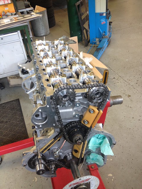
A few shots of the engine going back together
 IMG_1261 by Barkley Dogue, on Flickr
 IMG_1264 by Barkley Dogue, on Flickr
 IMG_1254 by Barkley Dogue, on Flickr
I had a call letting me know the block and head were ready so I made my way up to RG to collect all the necessary parts. I took everything I needed to put the engine together except for the head. This was assembled by RG and it was agreed with them that I would return the bottom end to them for their engine builder “woody” to put on and time up. An initial install of the crank was performed to ensure my crank and the new block were a good match. Luckily they were and I could run with standard bearings and not need any form of adjustment on the crank or main bearings.
Polished crank journals..
IMG_1218 - Copy by Barkley Dogue, on FlickrAssembling the bottom end was fairly straight forward. I wont go in to intricate detail as there are loads of decent books and resources out there to guide you through this. One which I found really useful was actually a US Honda tuning site they had a fairly interesting video http://www.evans-tuning.com/tech-videos/how-to-bui...
Before I did the real assembly I did a dry build to establish the pistons height above deck. I measured this with a dti and relayed the figures to RG, and everything was in order.
I bought a tapered ring compressor to install the pistons. Using the tapered ring compressor made installing the pistons incredibly easy. Obtaining one of these in this size in the UK took some doing.. to my knowledge this was the last one left in this country.
IMG_1171 by Barkley Dogue, on FlickrPut piston on rod, put rings on piston, verify ring gaps on piston, align rings, line up ring compressor and simply push in. The pistons could be installed in this way with just finger pressure. I lubricated all gudgeon pins with Toroco engine build lube and coated the cylinders with standard mineral oil.
Pistons, rods, and gudgeon pins ready for assembly..
DSC_0180 by Barkley Dogue, on FlickrPiston and rod dropped in through tapered ring compressor..
IMG_1247 by Barkley Dogue, on FlickrGentle pressure and it starts to locate into the bore...
IMG_1248 by Barkley Dogue, on FlickrAnd its in..
IMG_1249 by Barkley Dogue, on FlickrTaking no chances with dirt, I kept the bottom end heavily wrapped only unwrapping areas I needed access to when required.
Con rod installations was completed using Arp bolts. I’d never assembled the bottom end of an engine before so was fairly nervous considering the total cost of the parts involved, but I think if I had to do it again I’d feel more comfortable. The main thing is to take your time, and double check, and triple check everything, and at all stages make sure the engine feels right. Nothing should be binding. I marked everything as I went indicating it had been torque up as necessary.
The water pump and high pressure oil pump were rebuilt by RG as some tooling which I didn’t have was required, I could probably have fabricated these my self, but I really wanted to get the car back on the road before the end of summer. I did rebuild the scavenge pump which returns oil from the sump to the dry sump tank.
Scavenge pump..lots of bits..
IMG_1250 by Barkley Dogue, on FlickrAnd back together again.. bearings replaced and all O-rings renewed
IMG_1251 by Barkley Dogue, on FlickrAgain no rocket science here but it needs a patient logical approach, and thorough inspection of parts.
Although I completely understood the principal of timing the engine up with a degree wheel there were zero reference points to use. You essentially use a Degree wheel on the crank to find TDC, and a DTI on number 1 cam to determine the centre line angle. I took the decision in the end to have the head put on and timed up by RG, I had timed up the old engine, but felt more comfortable having it done by someone familiar with the FFF considering its cost and the fact I had to collect it as it required assembly. I couldn't even compare to the reference marks I made on my old head as the timing pf the new head would be somewhat different.
First glimpse of head waiting for assembly..
IMG_1227 by Barkley Dogue, on FlickrIMG_1223 by Barkley Dogue, on FlickrIt was almost too nice to use
Whilst the head was installed the existing duplex timing gear was replaced with RG’s simplex timing set up. The standard half time shaft of this engine was originally supported by a splash fed bearing, this was replaced by a pressure fed roller bearing. As well as the improved oiling to the bearing the simplex setup dropped a considerable weight from the timing set up, in the region of a kilo. On top of that specification of the simplex chain was more than good enough to offer the same load carrying capabilities to remove the duplex setup. In the January when I was researching components, I ended up in the RG parts warehouse along with Colin their MD, where we weighed the standard timing setup and the simplex on their mail room scales. I was suitably impressed.
Phwooooarrrr
IMG_1258 by Barkley Dogue, on FlickrThe standard head bolts were replaced with studs.
The simplex set up and the lightweight flywheel should ultimately help the engine spin up quicker!
In the RG workshop the head was put on by their engine builder “woody” (Steve Woodrow), I was lucky enough to get the chance to observe. Woody is another top guy who I’ve met along this journey, he was extremely patient and endured all of my questions. It was a really good learning experience and he gave me some top tips, which I wouldn’t have thought of, again giving me more confidence should the need arise in the future. Thanks again Woody!
A few shots of the engine going back together
IMG_1261 by Barkley Dogue, on FlickrIMG_1264 by Barkley Dogue, on FlickrIMG_1254 by Barkley Dogue, on FlickrEdited by m4tti on Wednesday 15th October 23:08
Edited by m4tti on Wednesday 15th October 23:09
Edited by m4tti on Saturday 18th October 20:04
Gassing Station | Readers' Cars | Top of Page | What's New | My Stuff