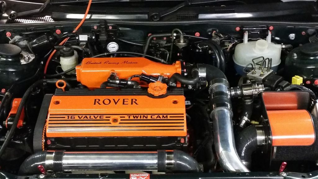
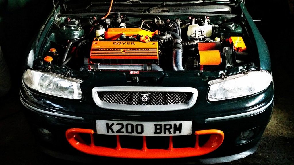
Rover 200 BRM - 1.8 K-Series turbo project
Discussion


Sorting a few other jobs out.
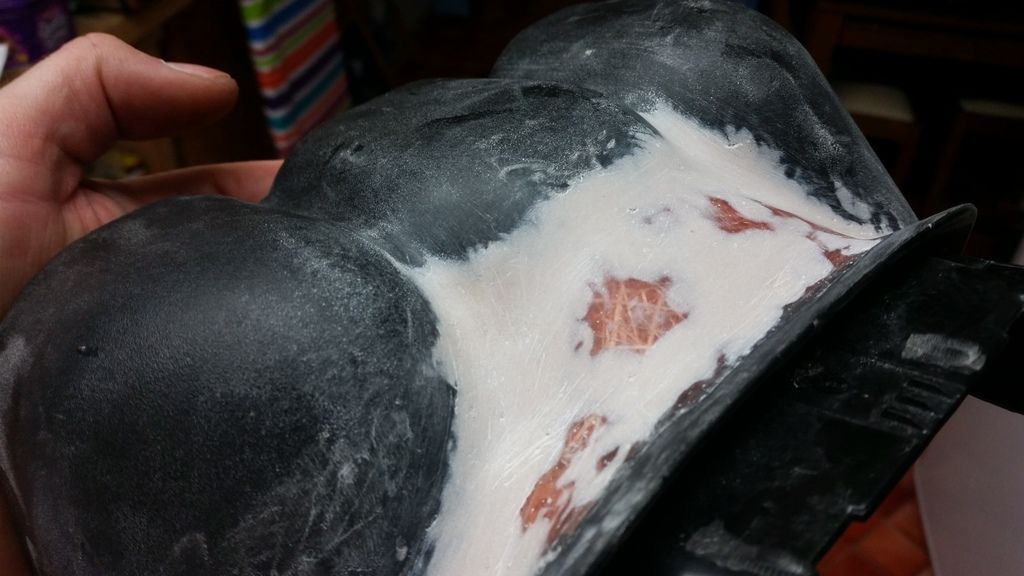
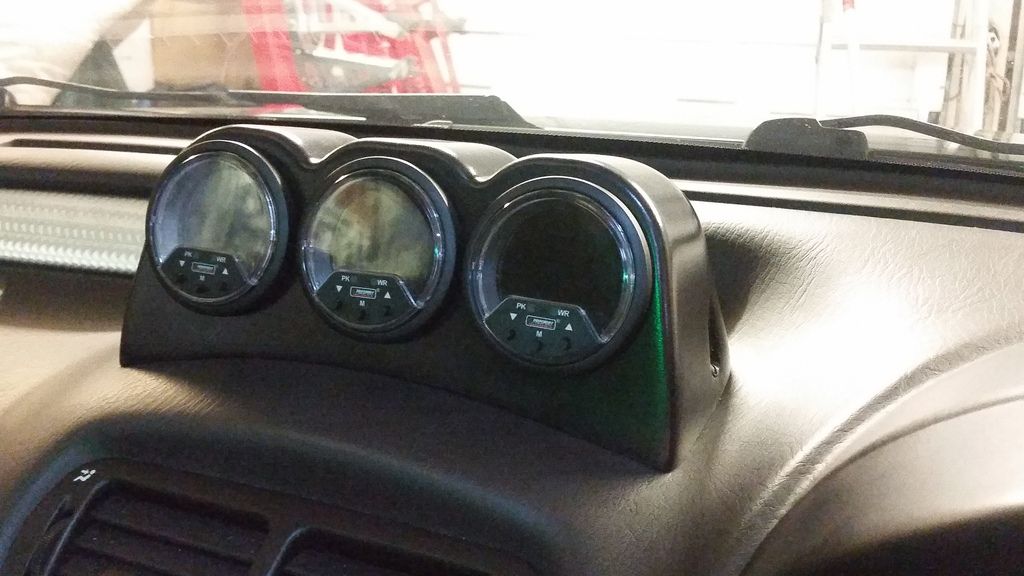
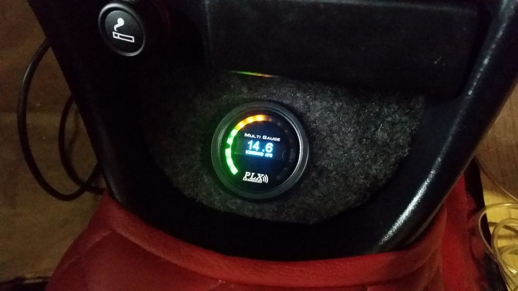
I wanted to run oil temp and pressure and boost gauges. Plus a wideband. I didn't fancy a pillar mounted gauge pod so opted for dash mounted. The dashboard is a very odd shape on the bubble so a three-gauge holder would need some fettling. Decided to integrate it with the clock (Rover clock never worked anyway!)
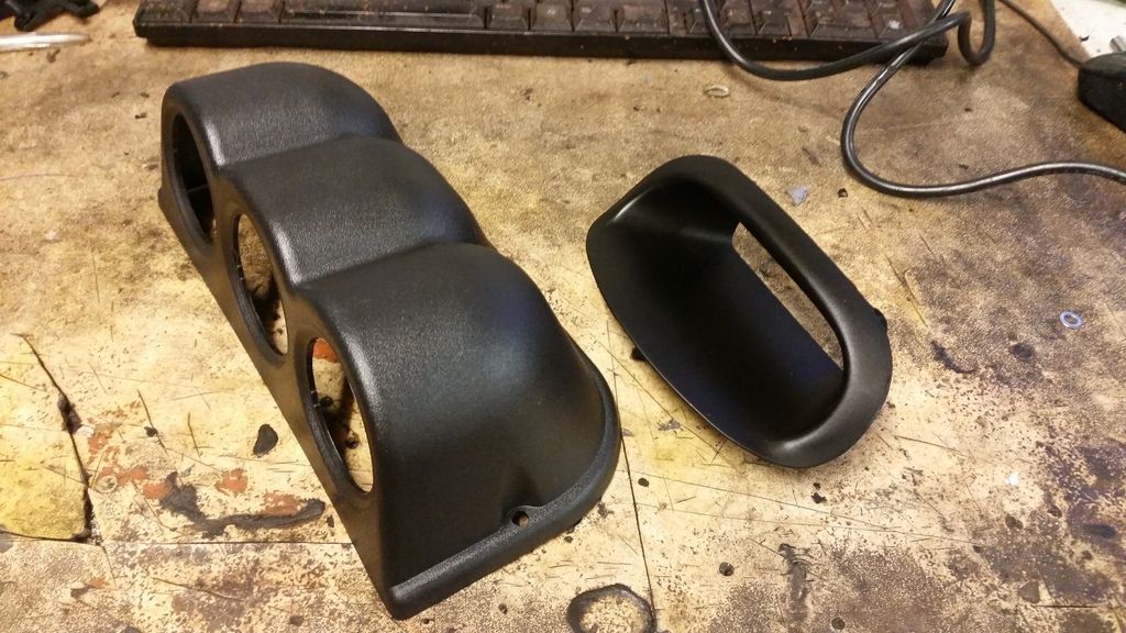
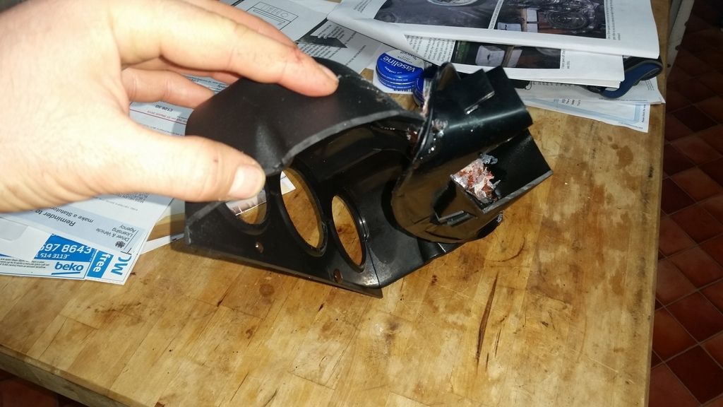
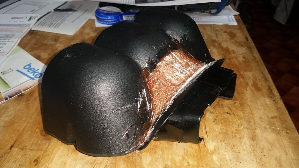
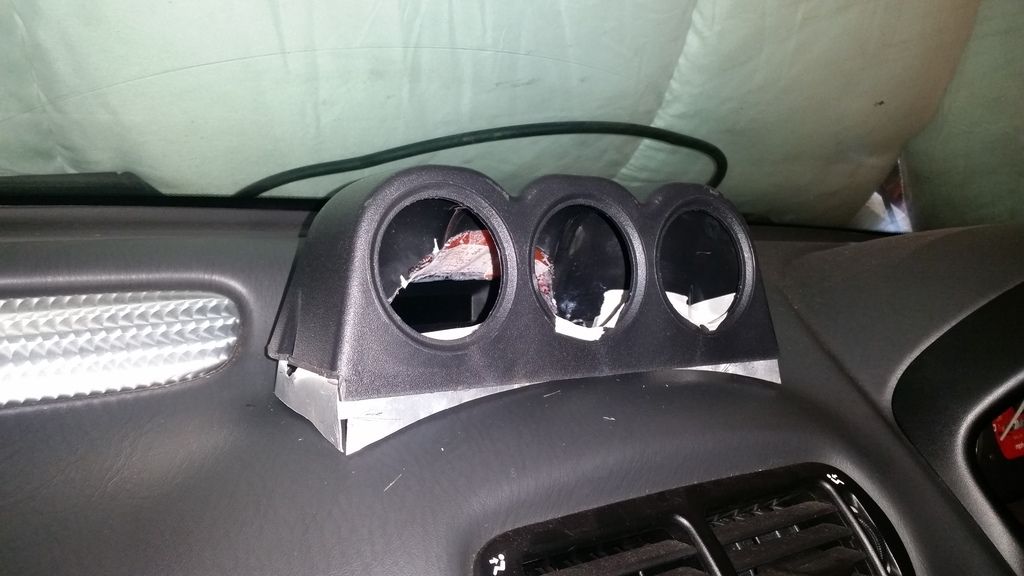
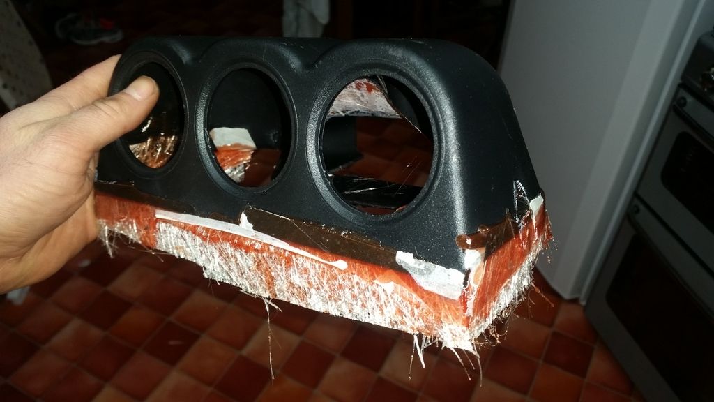
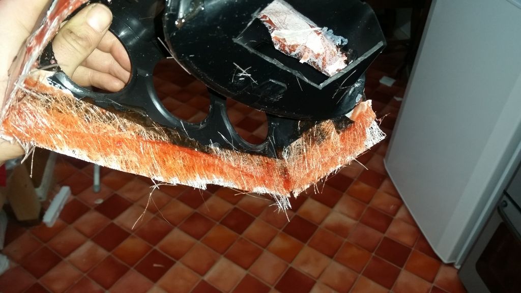
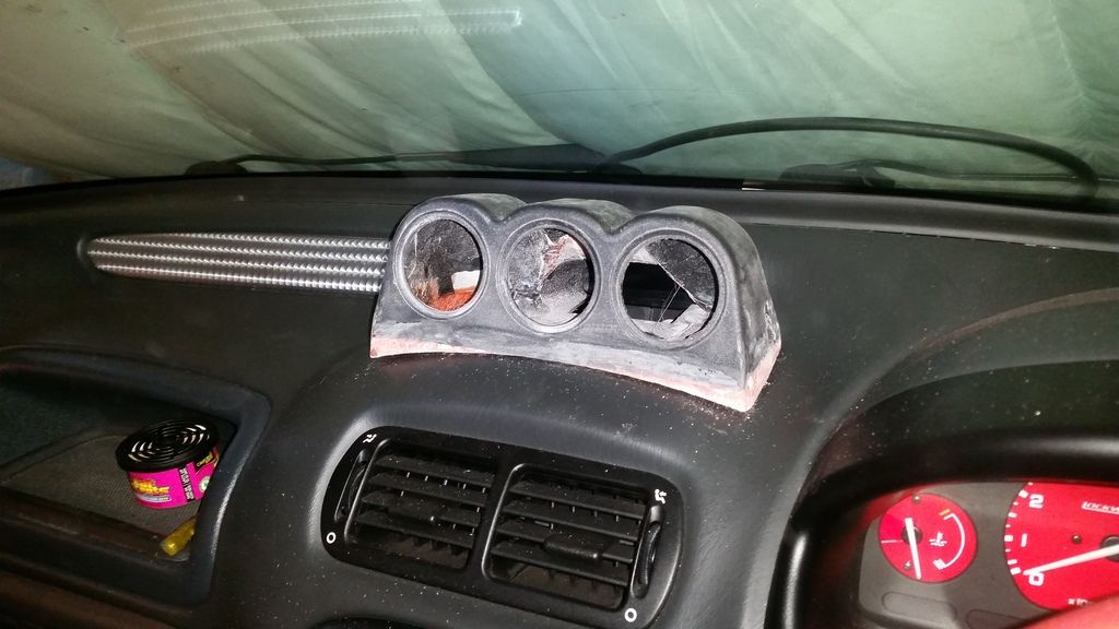
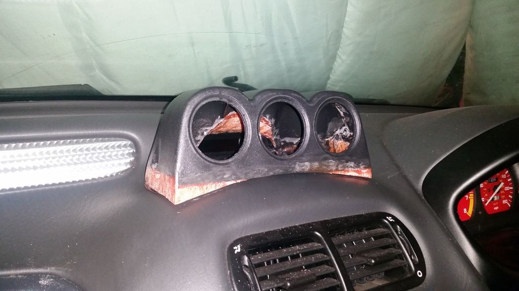
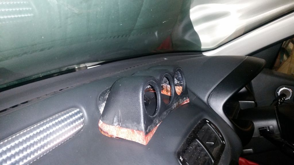
bit of filler:
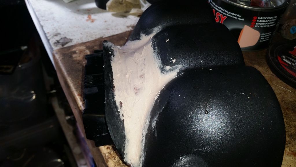
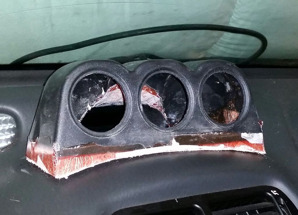
Bit of primer.
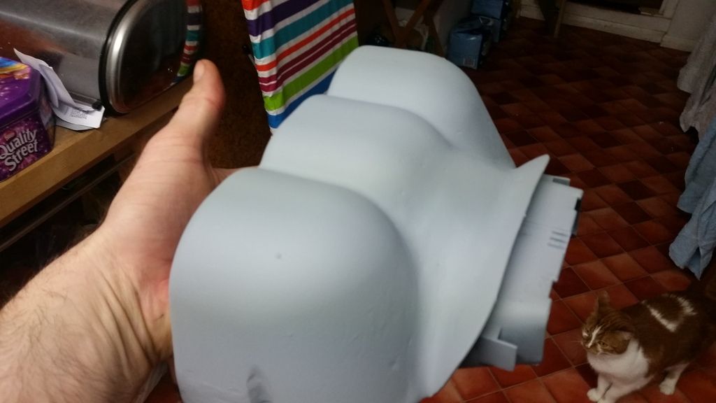
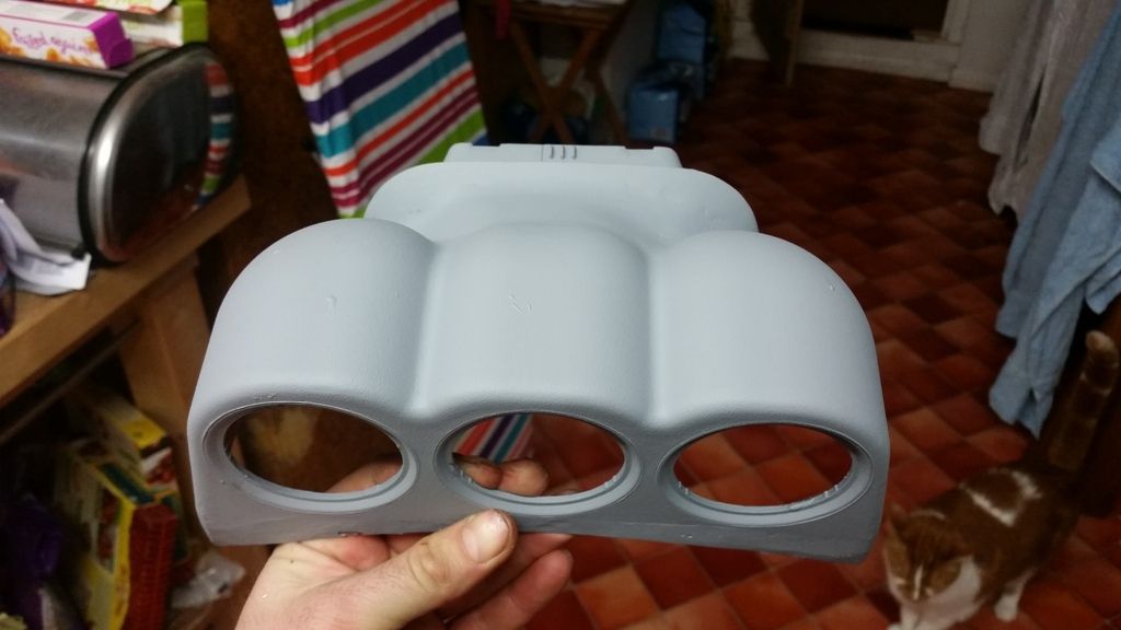
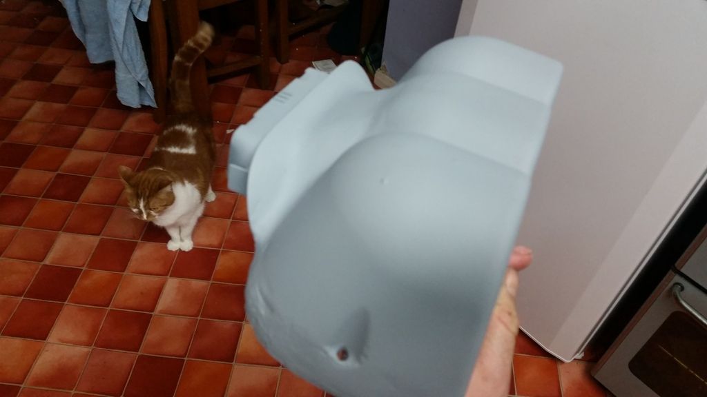
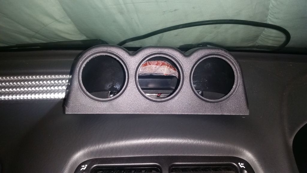
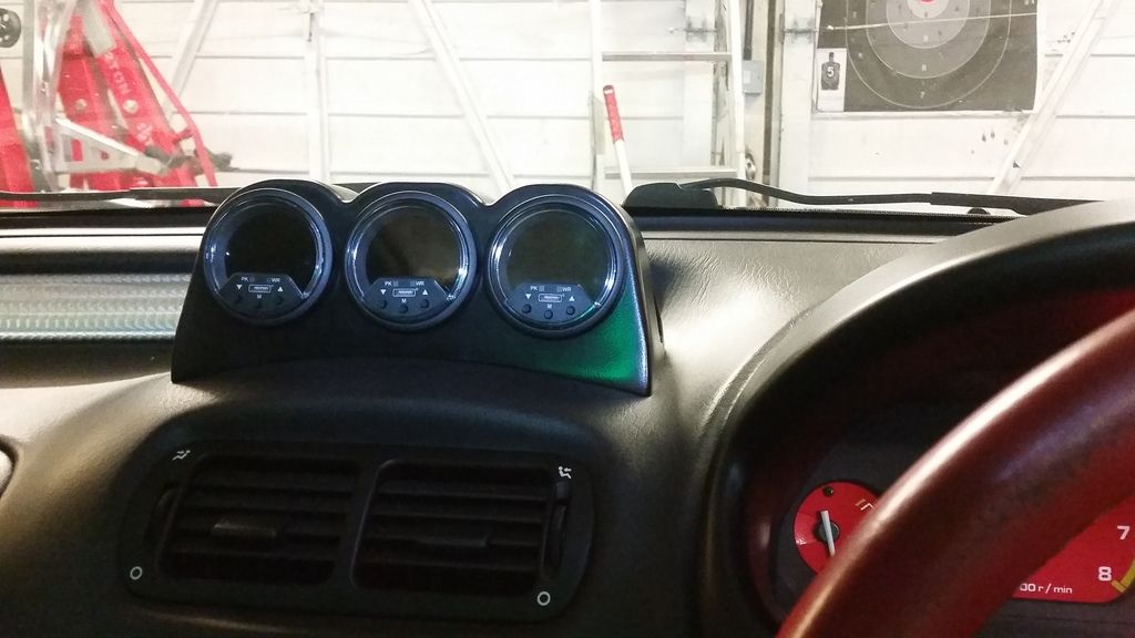
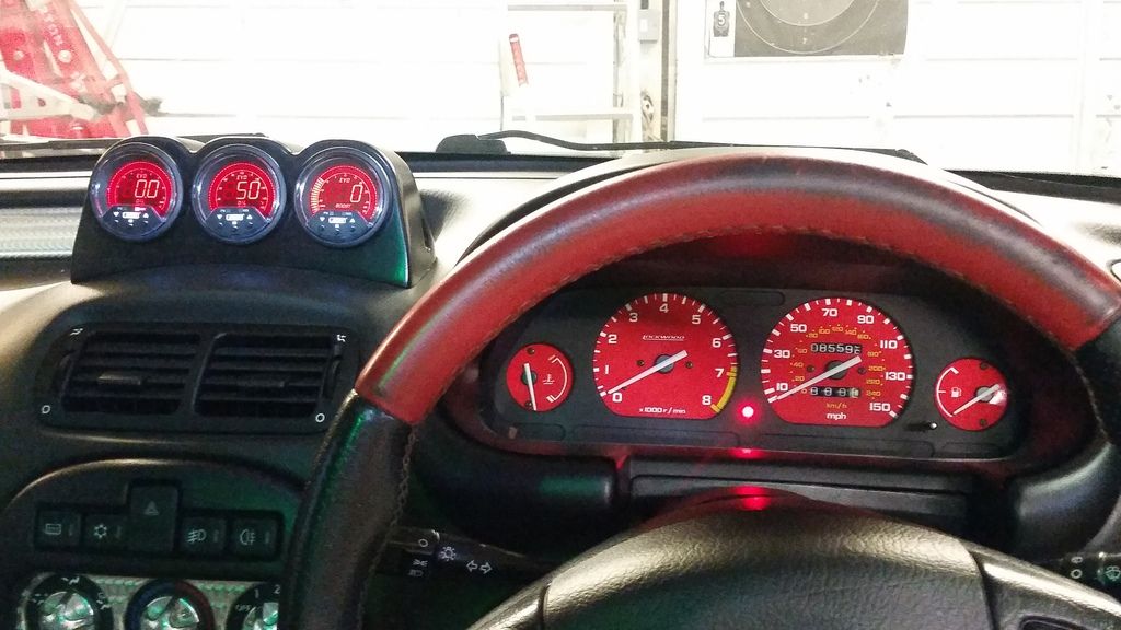
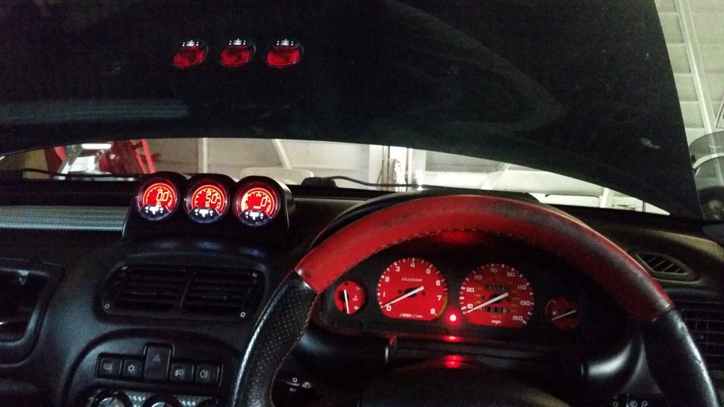
Several coats of filler primer and a coat of black plastidip type paint later. The gauges are awesome. Went with Prosport EVO gauges from r-spec. Oil temp, oil pressure and boost. They are 60mm and all digital.
http://www.youtube.com/watch?v=Xn7KoPY996k
And plx wideband installed down in the little storage cubby at the bottom of the centre console. This is basically 1mm aluminum plate shaped for an interference fit in the recess, then coated in acoustic carpet.
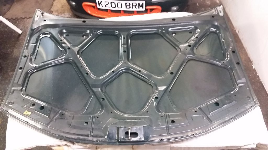
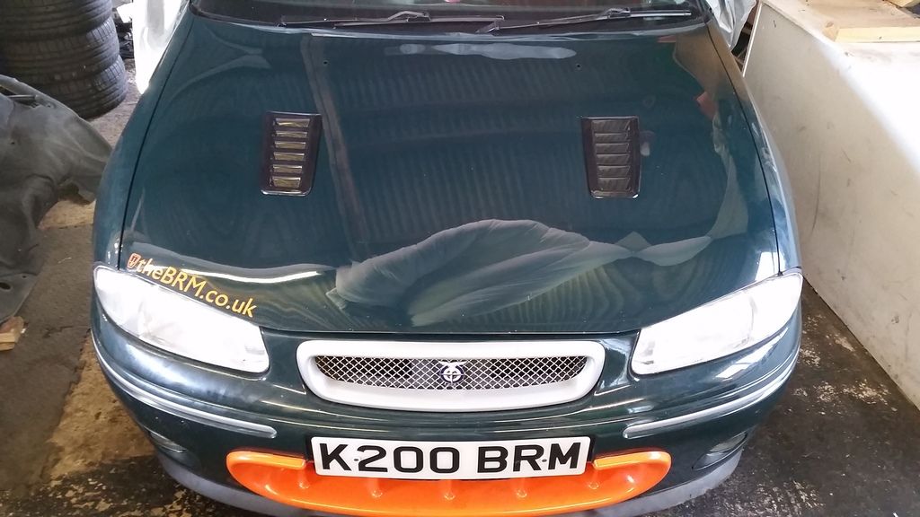
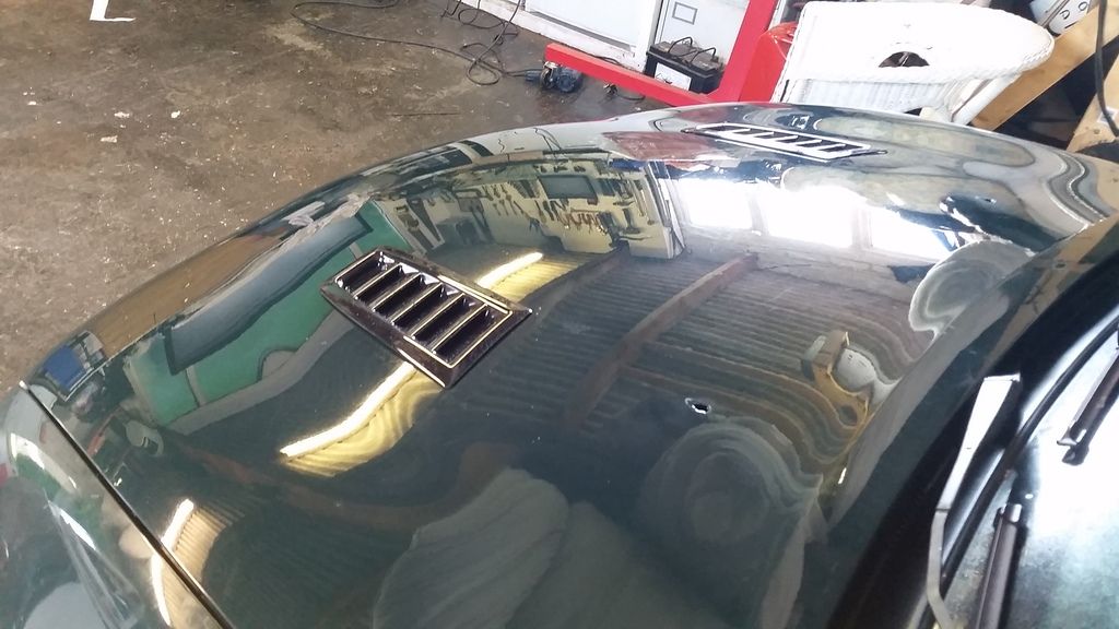
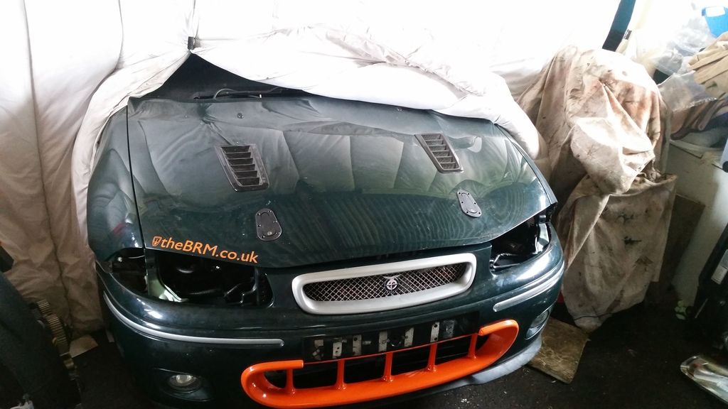
Meanwhile, you will have seen in earlier pictures I have bonnet vents. Whilst I wanted to keep the car looking resonably stock, I know temperature control will be important for this build so this was a necessary compromise.
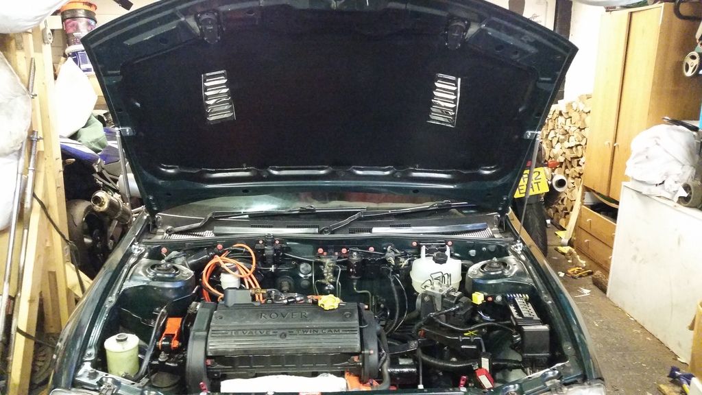
Bonnet off. The support struts seriously restrict location so I thought I'd just remove them! I know another guy who did this and as long as you keep the outside supports as they are and don't stand on the bonnet it's fine.
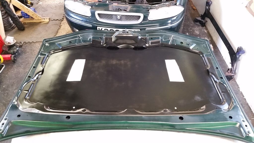
Fettled and cut.
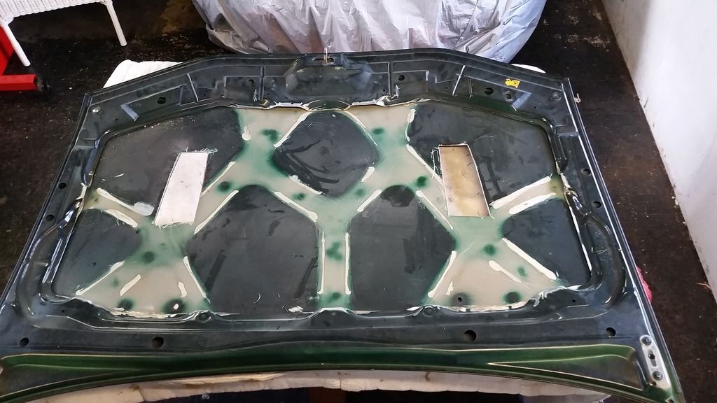
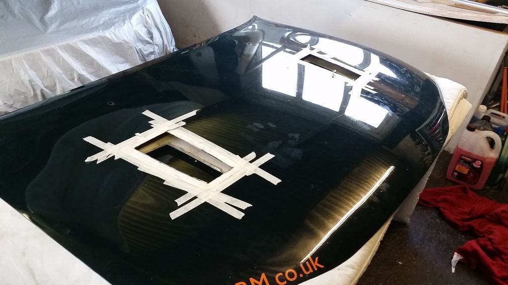
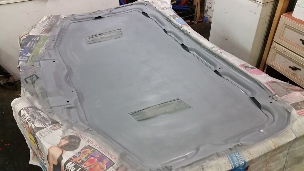
Temporary luck of paint until the full respray
Still had the old engine in when I did this...
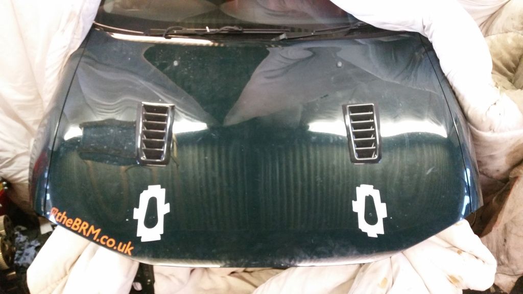
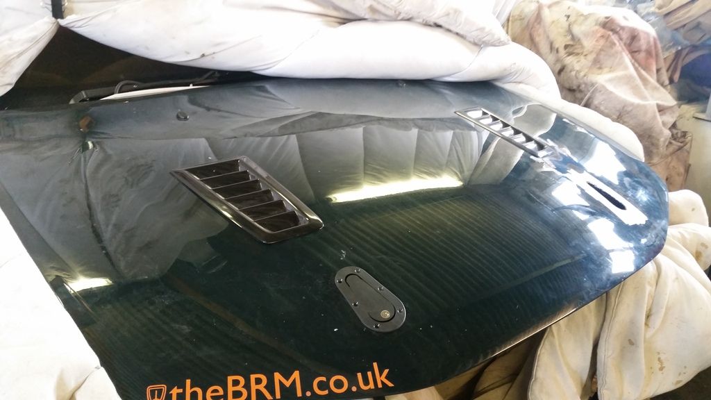
Next, to give myself a bit more room for radiator, oil cooler and intercooler, and to improve airflow, I deleted the bonnet catch upright support so had to fit something else to hold the bonnet down. I would have preferred some less substantial bonnet pins but that would be dubious when it came to the MOT so only option was to use aerocatches.
I deliberated for days on where to put them but in the end the least stupid seemed to be in line with the vents.
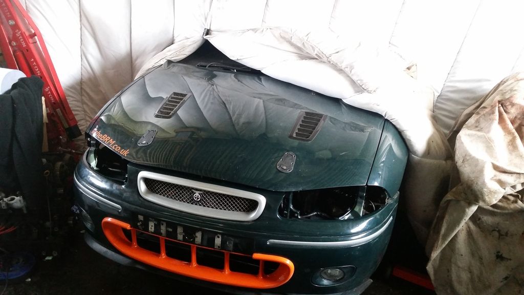
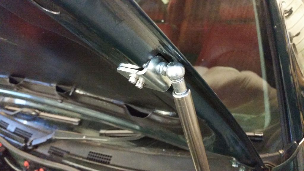
Fitting some gas struts:
I wanted to run oil temp and pressure and boost gauges. Plus a wideband. I didn't fancy a pillar mounted gauge pod so opted for dash mounted. The dashboard is a very odd shape on the bubble so a three-gauge holder would need some fettling. Decided to integrate it with the clock (Rover clock never worked anyway!)


bit of filler:


Bit of primer.


Several coats of filler primer and a coat of black plastidip type paint later. The gauges are awesome. Went with Prosport EVO gauges from r-spec. Oil temp, oil pressure and boost. They are 60mm and all digital.
http://www.youtube.com/watch?v=Xn7KoPY996k
And plx wideband installed down in the little storage cubby at the bottom of the centre console. This is basically 1mm aluminum plate shaped for an interference fit in the recess, then coated in acoustic carpet.
Meanwhile, you will have seen in earlier pictures I have bonnet vents. Whilst I wanted to keep the car looking resonably stock, I know temperature control will be important for this build so this was a necessary compromise.
Bonnet off. The support struts seriously restrict location so I thought I'd just remove them! I know another guy who did this and as long as you keep the outside supports as they are and don't stand on the bonnet it's fine.

Fettled and cut.


Temporary luck of paint until the full respray

Still had the old engine in when I did this...


Next, to give myself a bit more room for radiator, oil cooler and intercooler, and to improve airflow, I deleted the bonnet catch upright support so had to fit something else to hold the bonnet down. I would have preferred some less substantial bonnet pins but that would be dubious when it came to the MOT so only option was to use aerocatches.
I deliberated for days on where to put them but in the end the least stupid seemed to be in line with the vents.


Fitting some gas struts:
Edited by Stuballs on Wednesday 3rd January 13:26
Edited by Stuballs on Monday 22 January 12:58
Edited by Stuballs on Monday 22 January 13:00
Cooling. Very important in any tuned setup. Critical when playing around with the k-series.
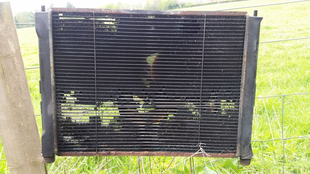
First and foremost I needed to sort out a radiator. Looked at a few options. Couldn't use the old one. Firstly because it didn't fit in the new forward position required by the sticky-out turbo. Also because it looked like this:
In the end, a friend through Rovertech sorted me out with a custom job all made in copper exactly to my specification.
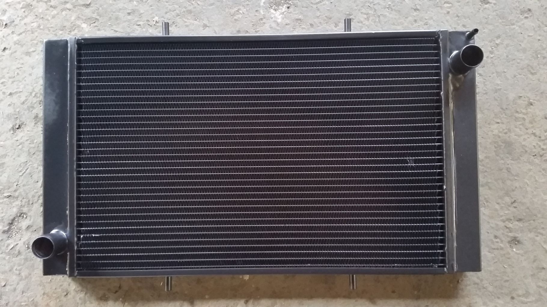
Opted for 2x10" Spal slimline fans mounted behind the rad. Fit like a glove.
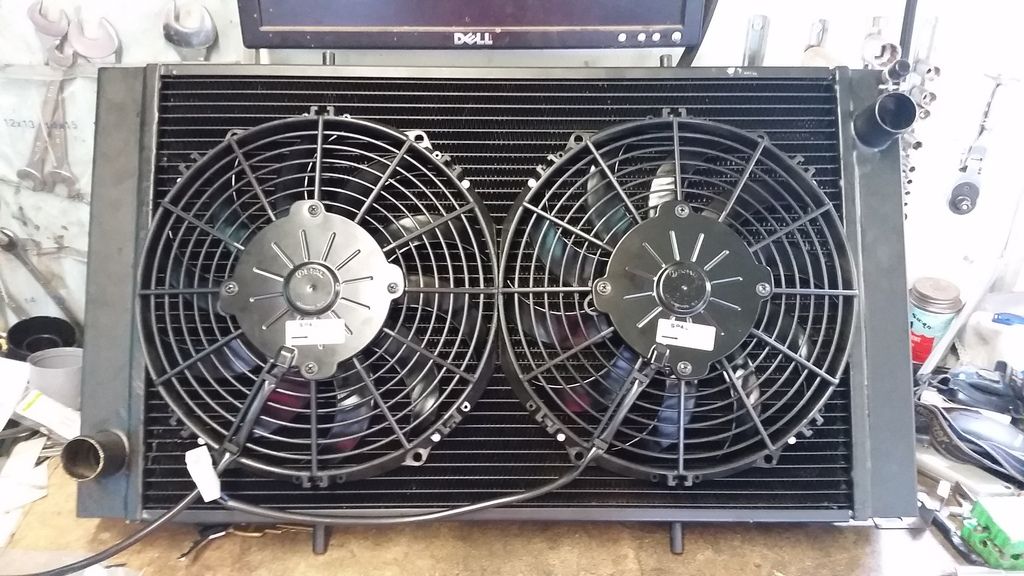
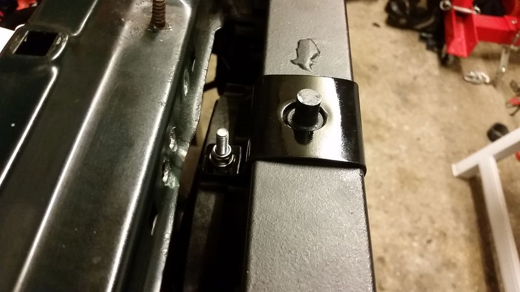
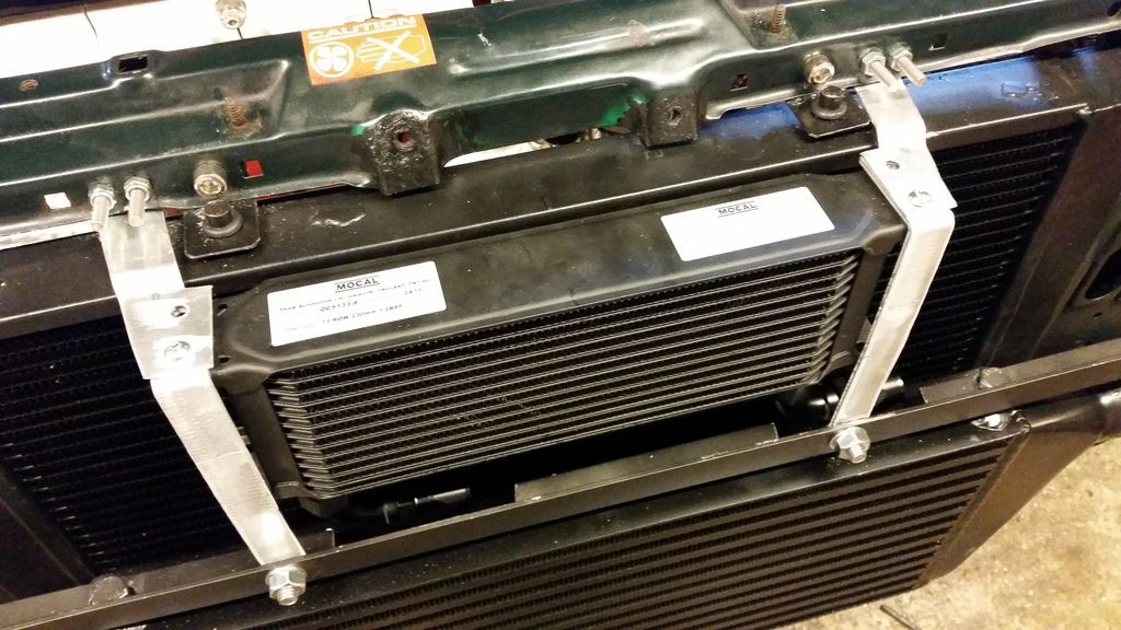
Had to make up all the brackets.
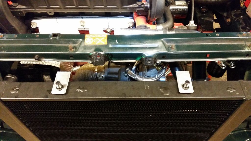
The fans are held in place by those locking rods that go through the core but the bulk of the weight is supported by these brackets.
I had my doubts as to whether my enormous downpipe would allow me to fit an oil cooler sandwich plate and filter in the stock location. As it happens, there wasn't even room to fit the filter!
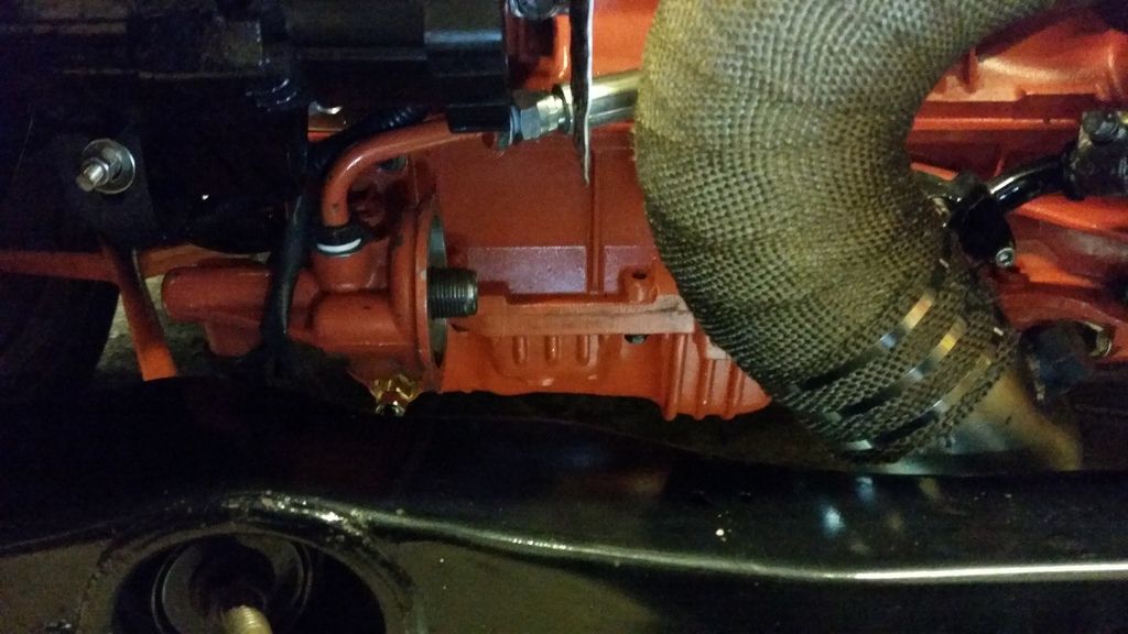
So I had a rethink and decided my only real option was a remote filter. I could then run the oil cooler sandwich plate on the remote head...
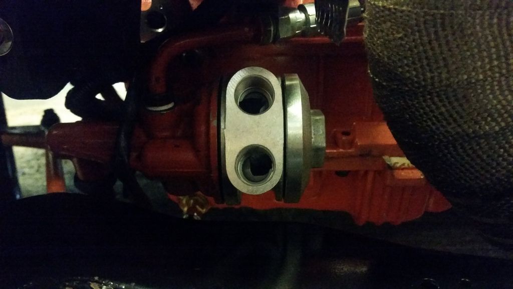
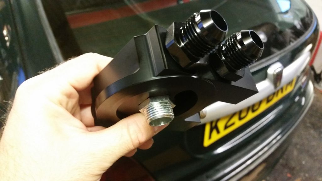
Here's the remote head:
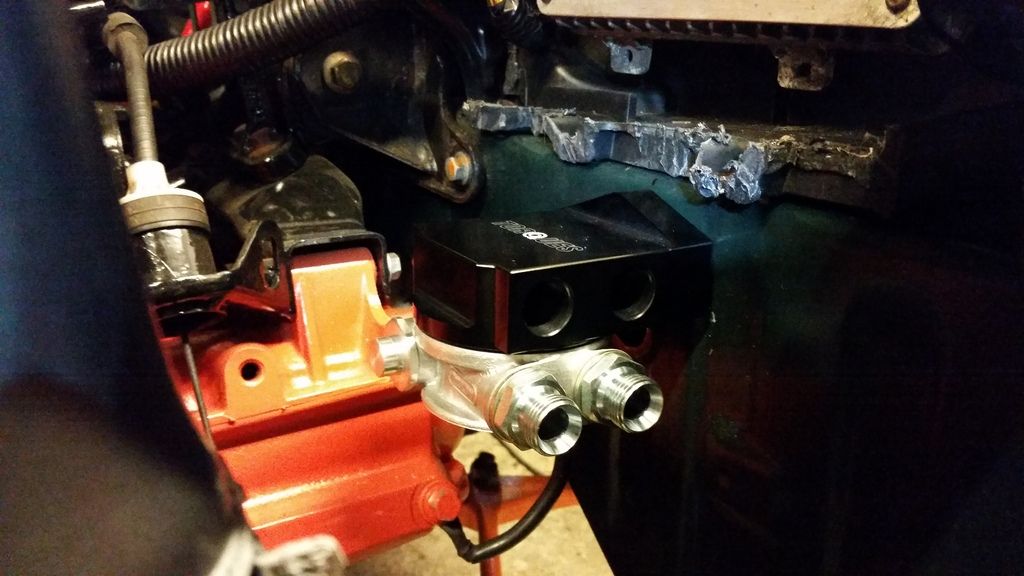
Only viable mounting position was under where the battery tray was. Fitted here with the sandwich plate.
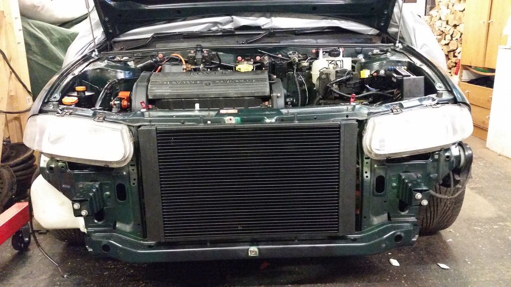
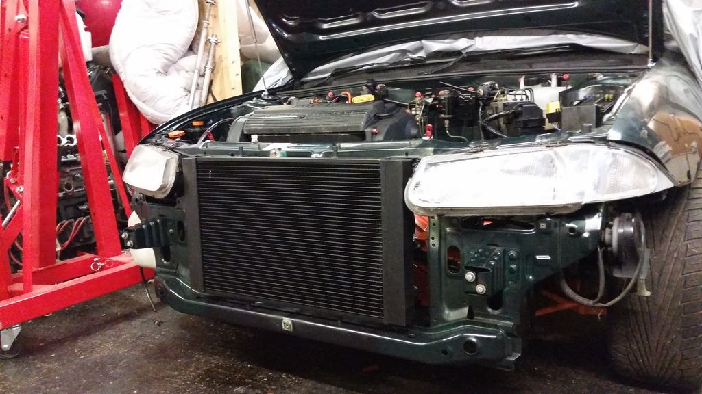
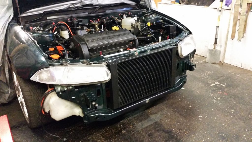
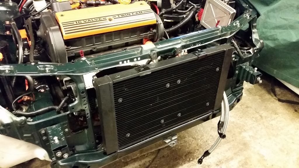
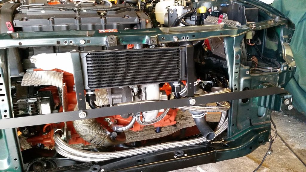
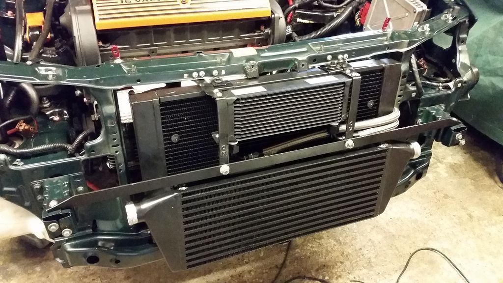
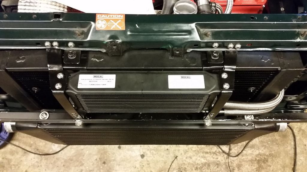
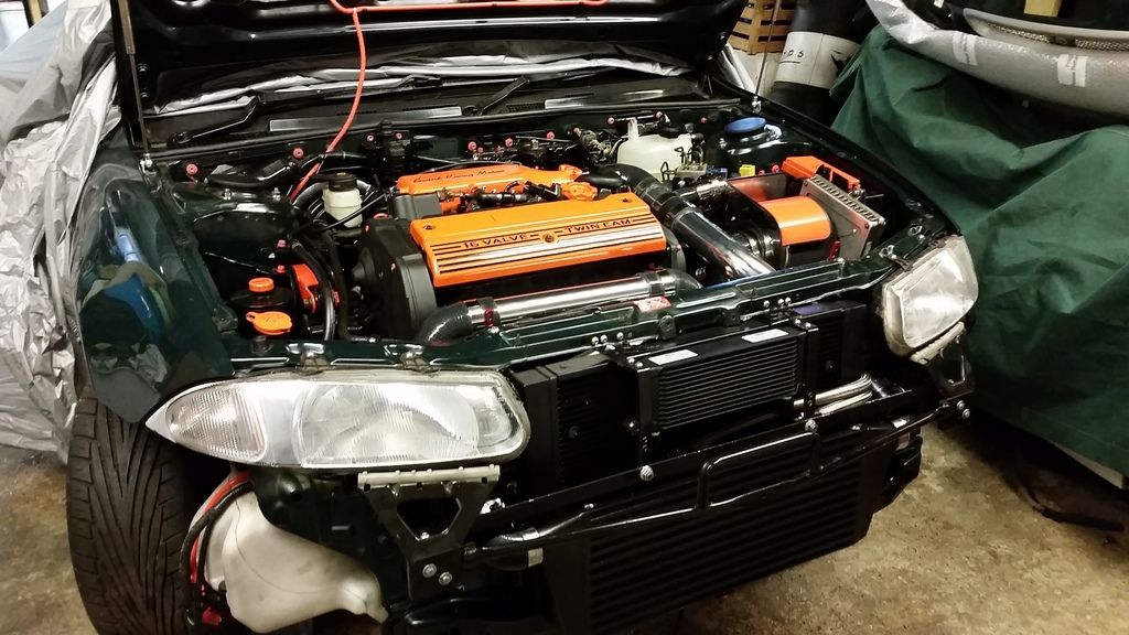
With that sorted out it was time to get the radiator, intercooler and oil cooler packaged up but first to paint the intercooler black for a more stealthy look.
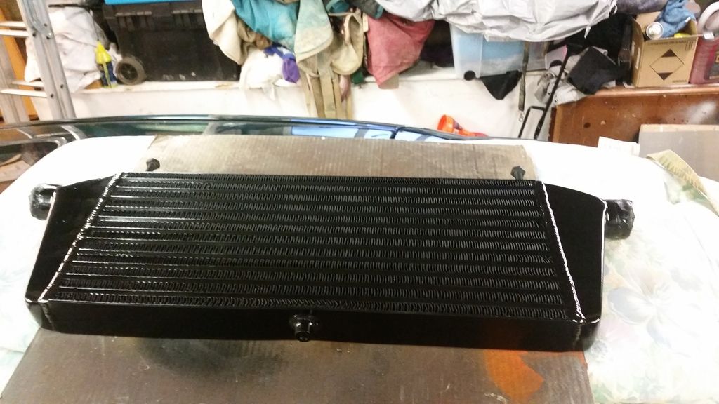
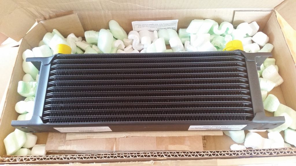
And here's the mocal oil cooler.
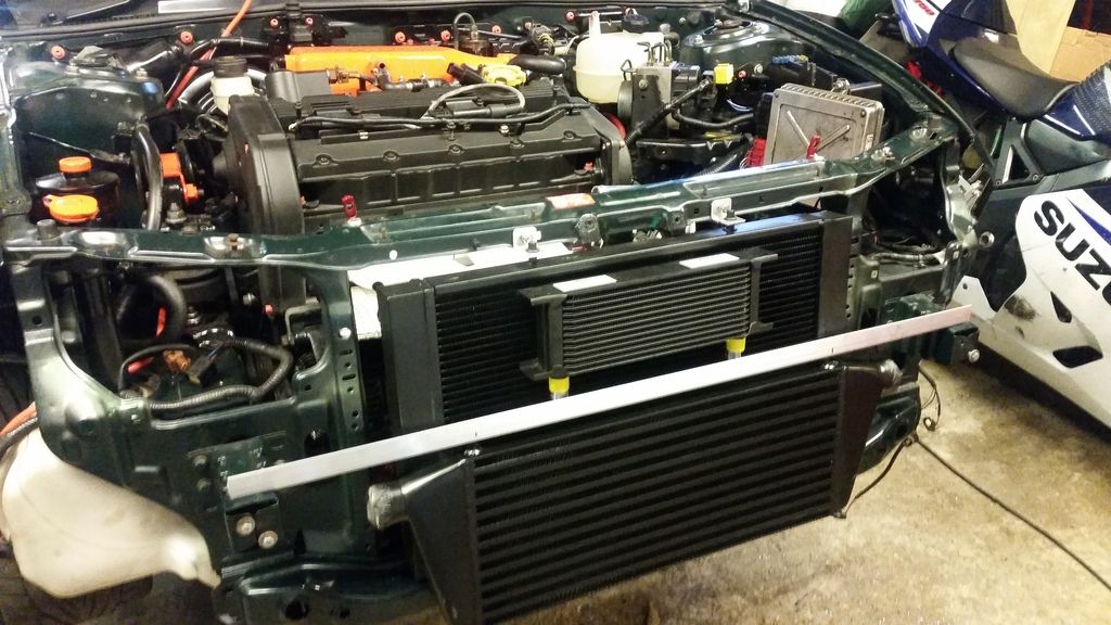
Trying to fit this lot behind the bumper was a nightmare. The orange snout projects a fair way behind the bumper so had to be trimmed slightly. As did the back of the top grill to clear the oil cooler.
More brackets
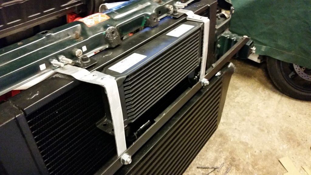
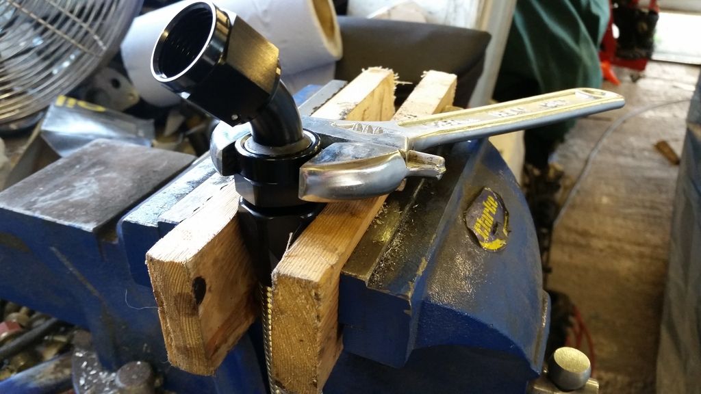
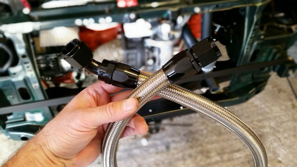
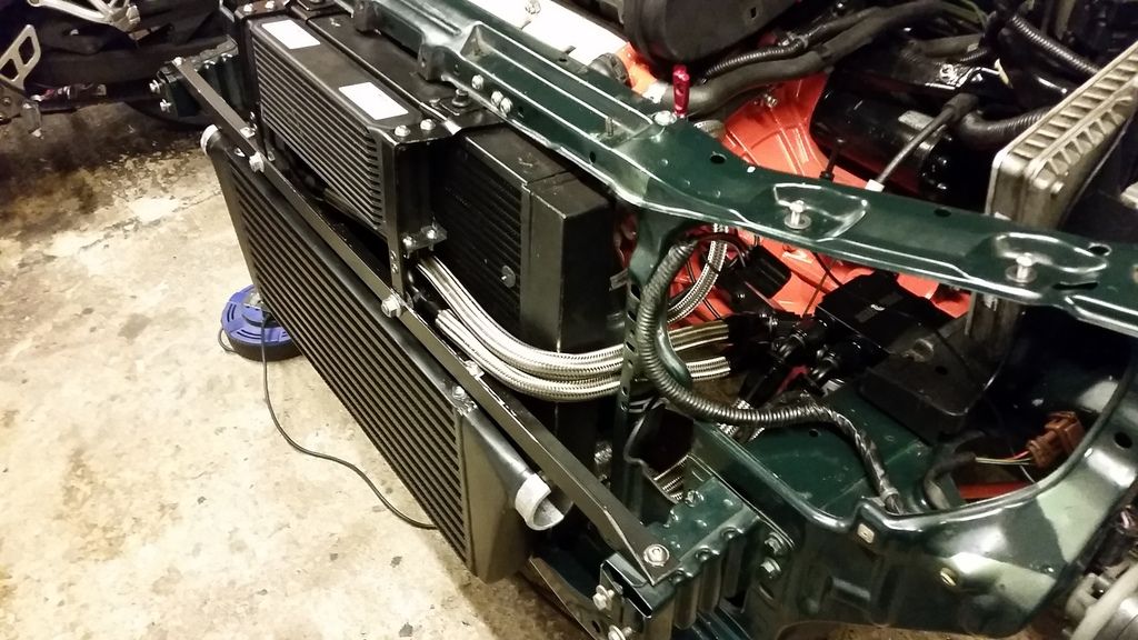
Making up the an-10 lines.
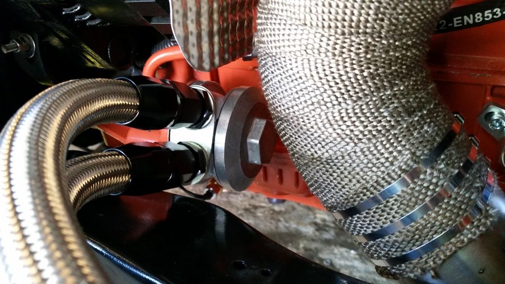
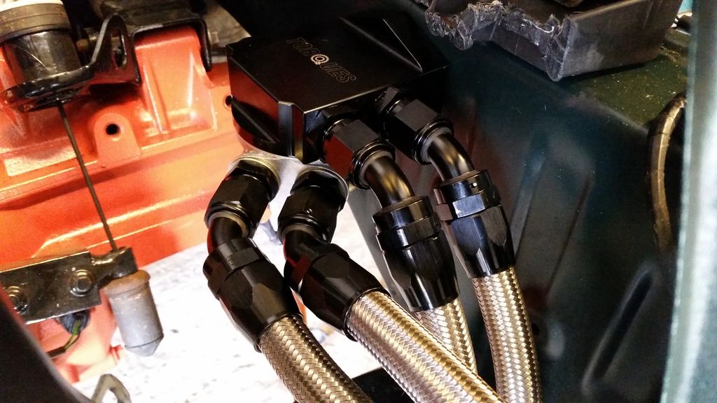
And getting it all bolted up with the final set of brackets painted black for more stealth.
First and foremost I needed to sort out a radiator. Looked at a few options. Couldn't use the old one. Firstly because it didn't fit in the new forward position required by the sticky-out turbo. Also because it looked like this:
In the end, a friend through Rovertech sorted me out with a custom job all made in copper exactly to my specification.
Opted for 2x10" Spal slimline fans mounted behind the rad. Fit like a glove.
Had to make up all the brackets.
The fans are held in place by those locking rods that go through the core but the bulk of the weight is supported by these brackets.
I had my doubts as to whether my enormous downpipe would allow me to fit an oil cooler sandwich plate and filter in the stock location. As it happens, there wasn't even room to fit the filter!
So I had a rethink and decided my only real option was a remote filter. I could then run the oil cooler sandwich plate on the remote head...
Here's the remote head:
Only viable mounting position was under where the battery tray was. Fitted here with the sandwich plate.
With that sorted out it was time to get the radiator, intercooler and oil cooler packaged up but first to paint the intercooler black for a more stealthy look.
And here's the mocal oil cooler.
Trying to fit this lot behind the bumper was a nightmare. The orange snout projects a fair way behind the bumper so had to be trimmed slightly. As did the back of the top grill to clear the oil cooler.
More brackets
Making up the an-10 lines.
And getting it all bolted up with the final set of brackets painted black for more stealth.

Edited by Stuballs on Monday 22 January 12:56
Edited by Stuballs on Monday 22 January 13:01
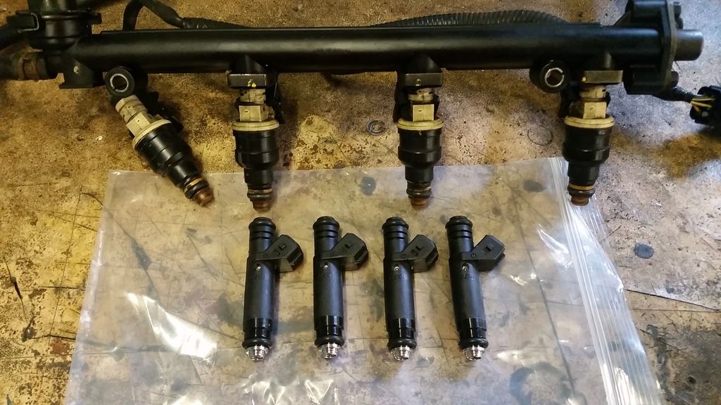
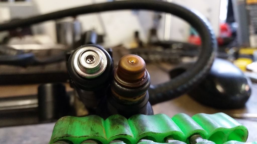
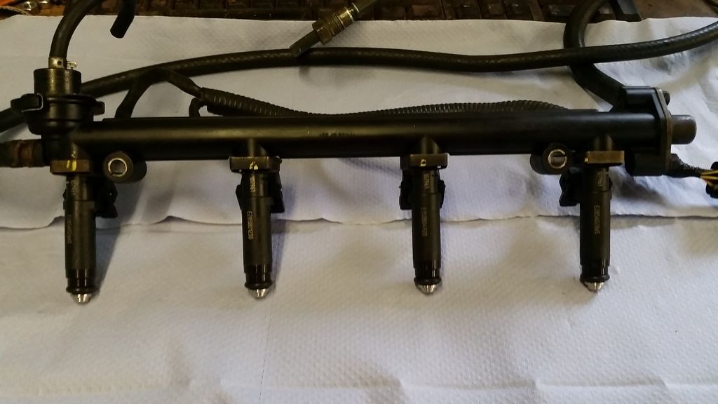
Next job was to fit some larger injectors. Standard are 210cc so are nowhere near enough for my requirements. Since I'm running Emerald management I opted for some 660cc Siemens Deka jobbies which are high impedence. Straight replacement for the standard injectors.
I worked out I would need static fuel flow of around 525cc for 300bhp with an 80% duty so these are just the ticket. Plenty of headroom.
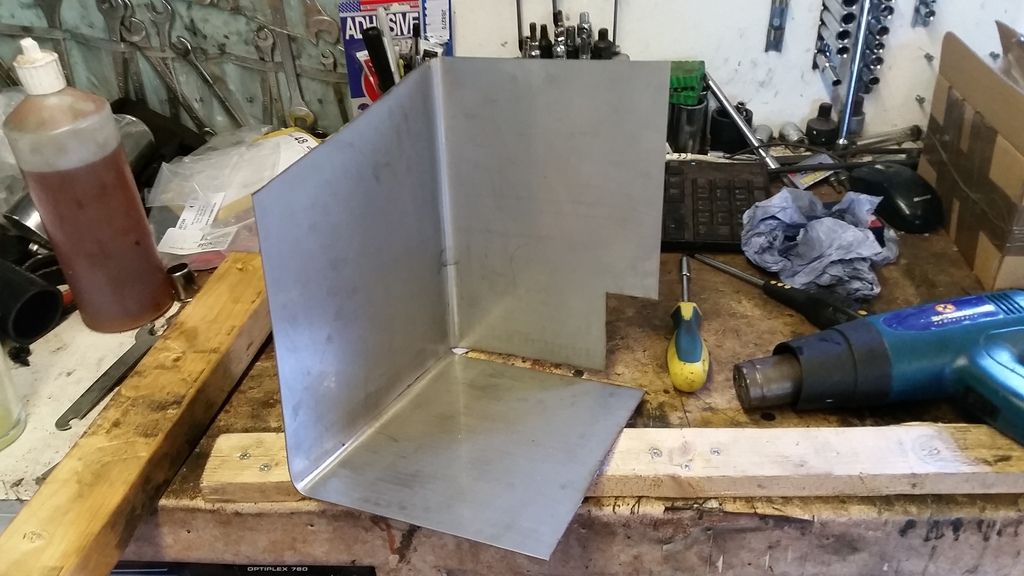
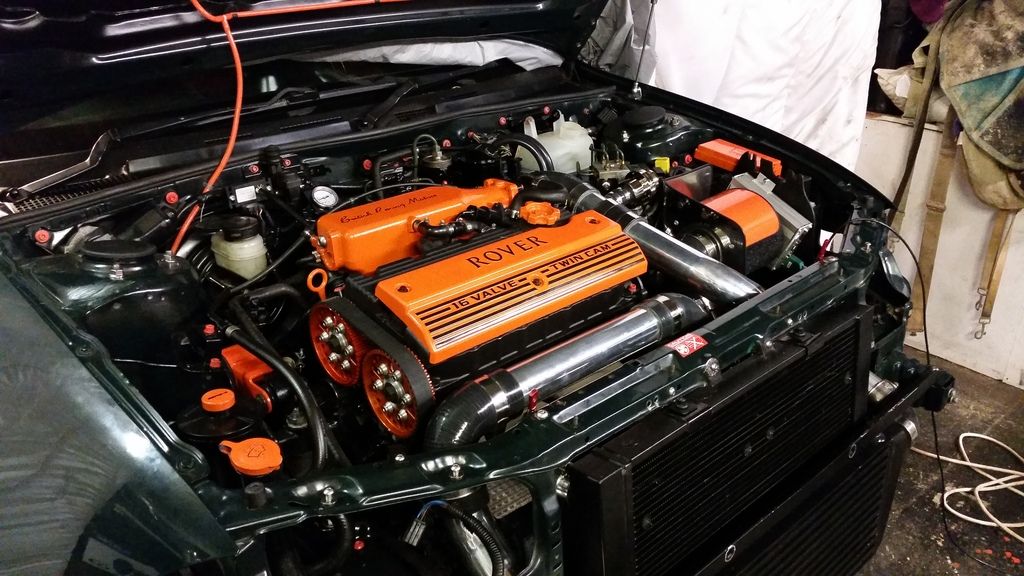
With the inlet manifold all sorted I thought I might make myself a heat shield for the air filter.
Mocked up in cardboard:
Sheet of stainless off ebay bent to shape and fettled :
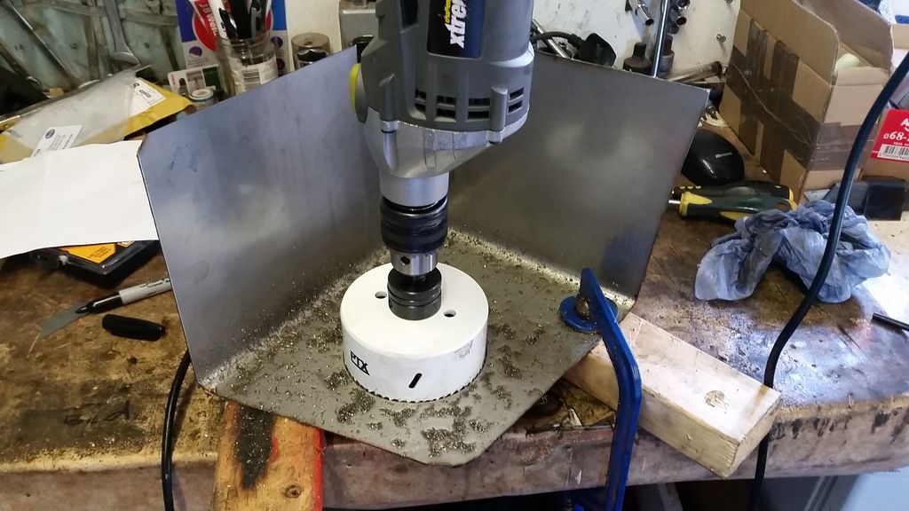
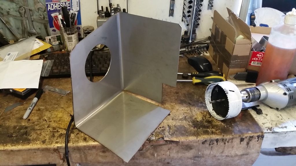
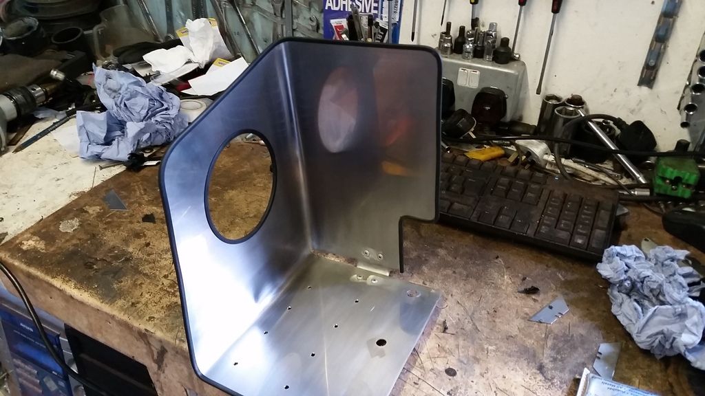
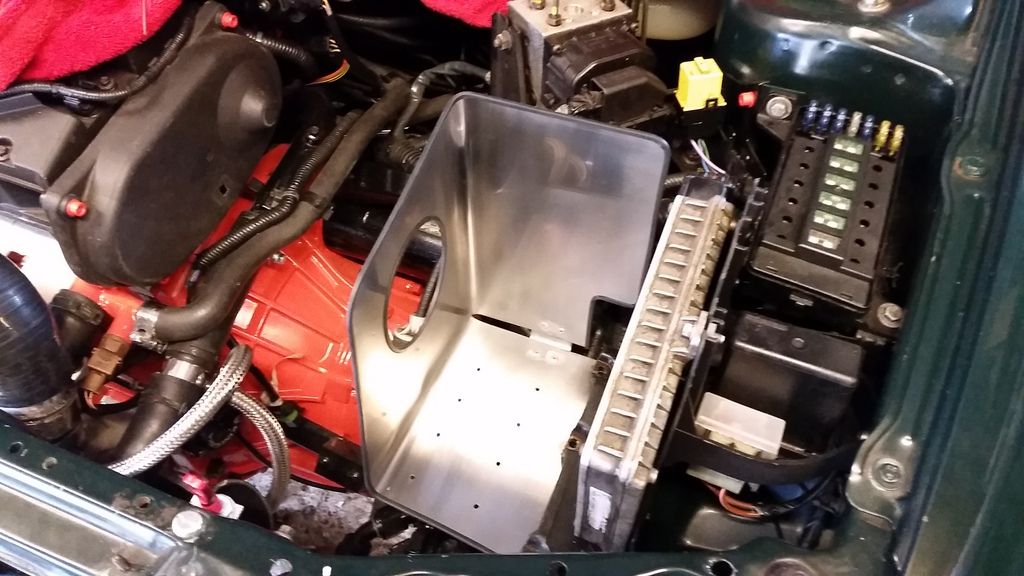
I don't have any pictures of putting the intake pipework together but suffice to say it was a long painful process getting it just right!
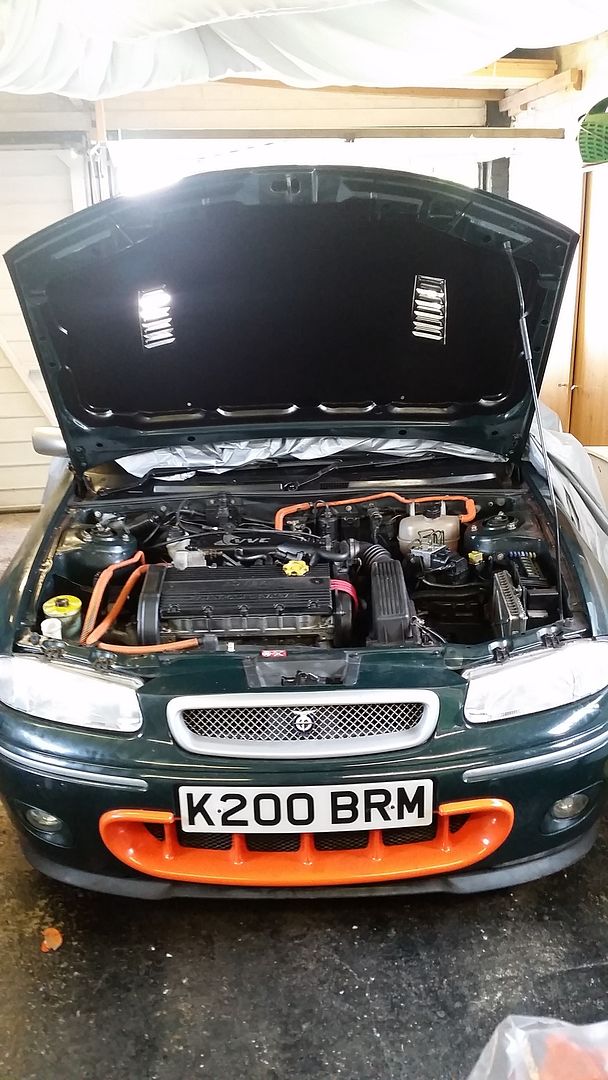
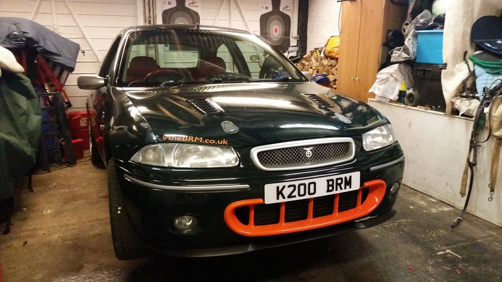
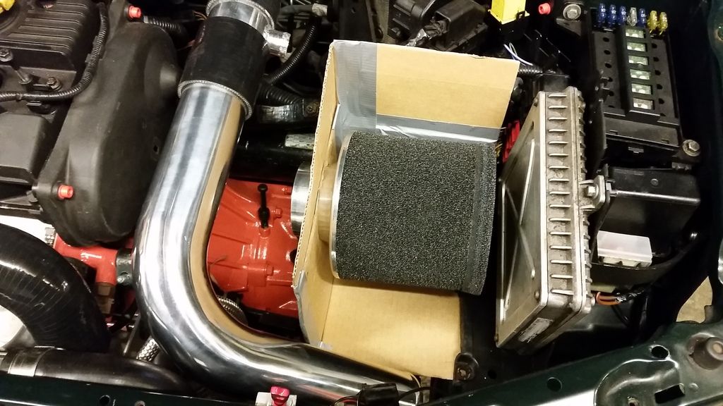
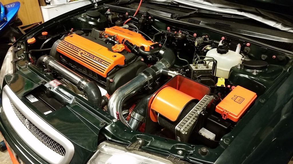
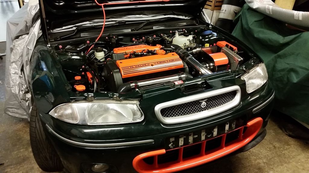
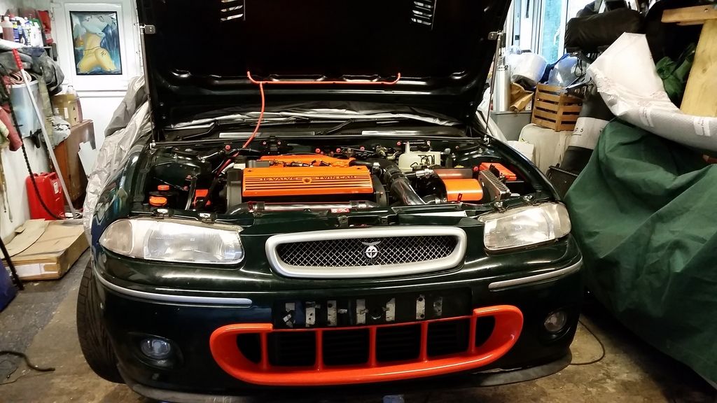
I also modified a cone filter heat shield to fit it to my stainless box. I thought the orange would balance out the bay a bit more but the main purpose is to stop the filter getting drenched if water ever finds its way through the bonnet vent.
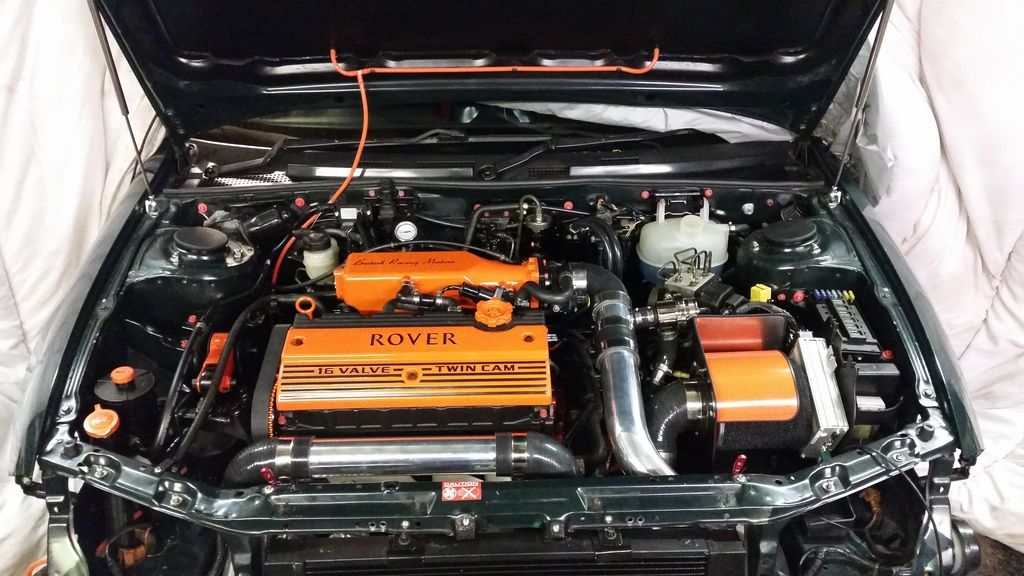
And here's how she sits now :
I worked out I would need static fuel flow of around 525cc for 300bhp with an 80% duty so these are just the ticket. Plenty of headroom.
With the inlet manifold all sorted I thought I might make myself a heat shield for the air filter.
Mocked up in cardboard:
Sheet of stainless off ebay bent to shape and fettled :
I don't have any pictures of putting the intake pipework together but suffice to say it was a long painful process getting it just right!
I also modified a cone filter heat shield to fit it to my stainless box. I thought the orange would balance out the bay a bit more but the main purpose is to stop the filter getting drenched if water ever finds its way through the bonnet vent.
And here's how she sits now :
Edited by Stuballs on Monday 22 January 13:05
Thanks for the comments guys.
ManOpener said:
Really impressive, particularly how OEM the engine build looks!
My brief to myself was to keep it looking fairly oe but smarter with a bit more colour, but not over the top. I'm very pleased with it so far. mk2 24v said:
+1 
I presume as you used Powerspeed to do the exhaust?
YupI presume as you used Powerspeed to do the exhaust?
AWG said:
Stu, what did you use for the oil/intercooler? Powder coat, etch primer?
Just etch primer and some chip Andy. Although oil cooler was supplied painted. I thought a big silver intercooler behind the orange mouth would look a bit odd. Polynesian said:
please also consider painting the upper grille (the rover one) the brg of the body to draw the eye to the BRM "grille"
I'll certainly consider it although I've never had a problem with it. Might play around with photoshop. As standard it's a chrome grill but the previous owner painted it sparkle silver to match the rest of the trim (mirrors, wheels, bumper trim) which I think works better. Another option would be to repaint all the sparkle silver bits a darker gunmetal grey or anthracite to dull it down a bit. Might look a bit more menacing too. But that would also take away from the BRM identity and I wanted to avoid changing the look unless I had to for functional reasons First start!
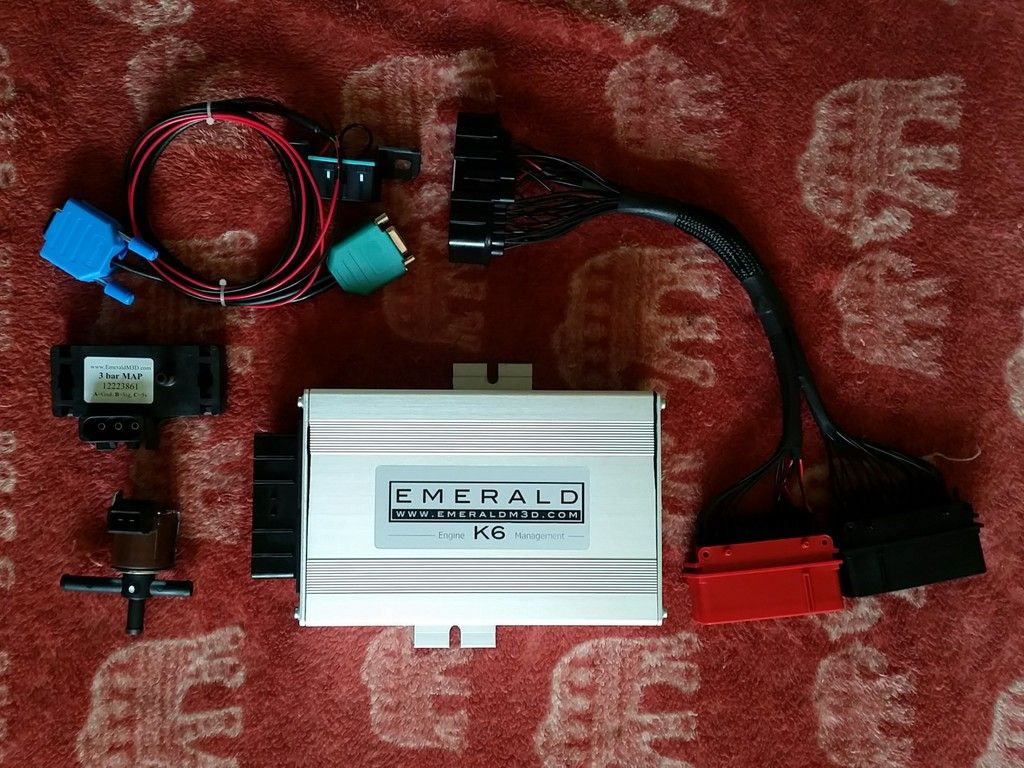
Got the Emerald installed with the supplied adapter loom for plug and play (although they forgot to install the boost control solenoid wiring so it had to go back) . They also supplied a 3 bar MAP sensor and a boost control solenoid. The first mapping will be at actuator pressure (about 8psi) so the solenoid is not doing anything at the moment. After run in I'll map for full power at around 16psi.
Filled up with Millers running in oil and coolant and she's ready to go. Disable injectors and ignition and turn over on the key to check it turns over and to get oil pressure. All fine so far. I'm getting nervous. I've never done this before. Maybe I should wait to get a couple of buddies round to act as extra pairs of eyes during this delicate time. I man up, plug everything back in, and turn the key.
BINGO! Fired up instantly!
A few tweaks of the Emerald to lower the Idle and then my eyes are trying to look at a million things at once! You really want minimal running at idle on a new build. The sooner you can get the engine under load and start bedding the rings in the better. So I checked for fuel, oil and coolant leaks and checked all temps and pressures were fine. Oil was struggling to get above 60 degrees C and it was clear the "thermostatic" oil cooler setup was over cooling (or the sensor was faulty). I had a couple of small coolant leaks that were sorted by nipping up clamps but other than that everything was fine.
And little vid of it running:
http://www.youtube.com/watch?v=O-zvICWkZ24
My initial reaction was "Jesus that top end is noisy". I assumed it was the VVC mechanisms as they are notoriously rattly and I've never heard a quiet setup - This is particularly bad though. That said, they hardly ever fail completely so my intention was to crack on with mapping and see how it goes. This, it turns out, was a mistake...
Rattling aside, I think it sounds great. The dump valve is a lot louder than I expected given its a recirculating system, but I kinda like it.
Time for mapping...
Booked in to see HT Racing who are based at Brands Hatch and had it trailered down there. Things were going well... At first...
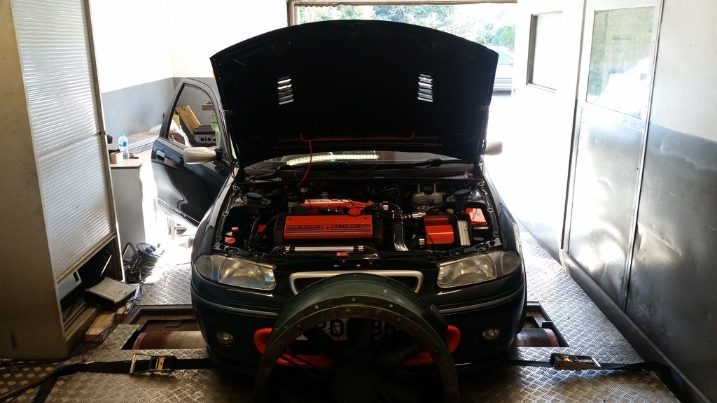
A little vid of one of the runs:
http://www.youtube.com/watch?v=vGEZjrXCSKk
Then it all went a bit wrong...
We were almost done but then for no reason she developed a misfire at idle and low rpm. Lost compression in cylinder 3.
F#&k
Ok not the end of the world - might just be a sticky lifter. Definitely mechanical though so obviously I'm thinking "what have I done wrong?"!
Load back on the trailer and return home somewhat dejected with some further investigations to do.
I ran a compression leak down test. This is basically where you add compressed air to the cylinder with the piston at top dead centre on the compression stroke (so all the valves should be closed) and measure how quickly it leaks away. Around 10% would be normal on a new build and you want consistency across all cylinders. On cylinder 1,2, and 4 I had about 10%. On cylinder 3 I had 60%!
The clever bit about a leak down test is that you can tell what kind of problem you have by where the air is coming out. In my case it was rushing out of the throttle body, telling me I had an inlet valve stuck open. This could be a number of things so time to whip the head off.
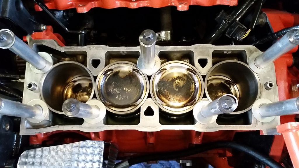
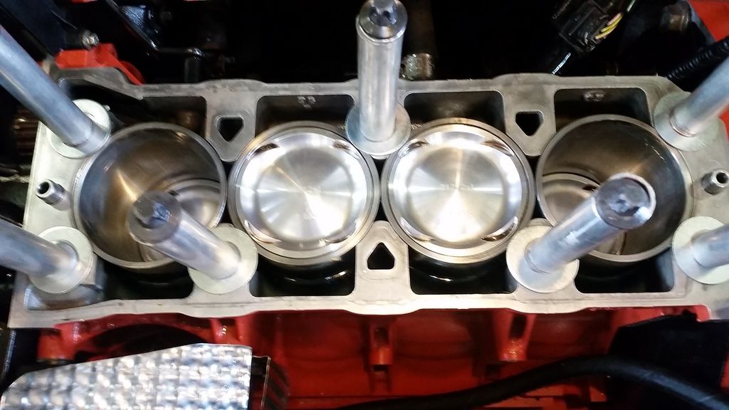
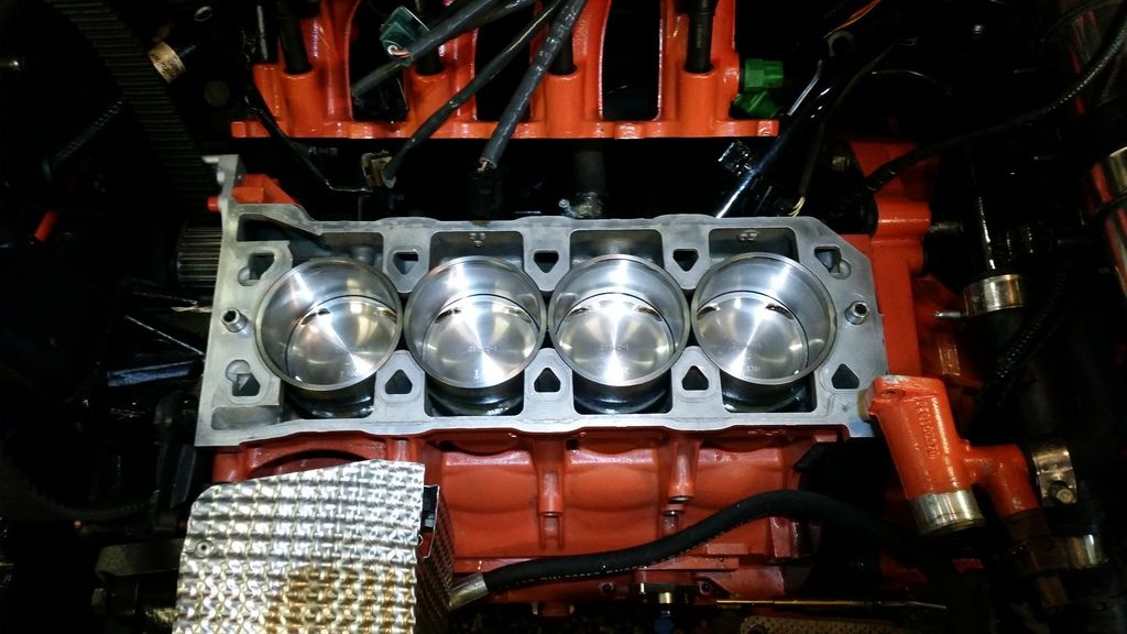
Head off. Firstly, I obviously got a bad batch of valve stem oil seals as most of them are leaking! Pistons are coated although cleaned up nicely.
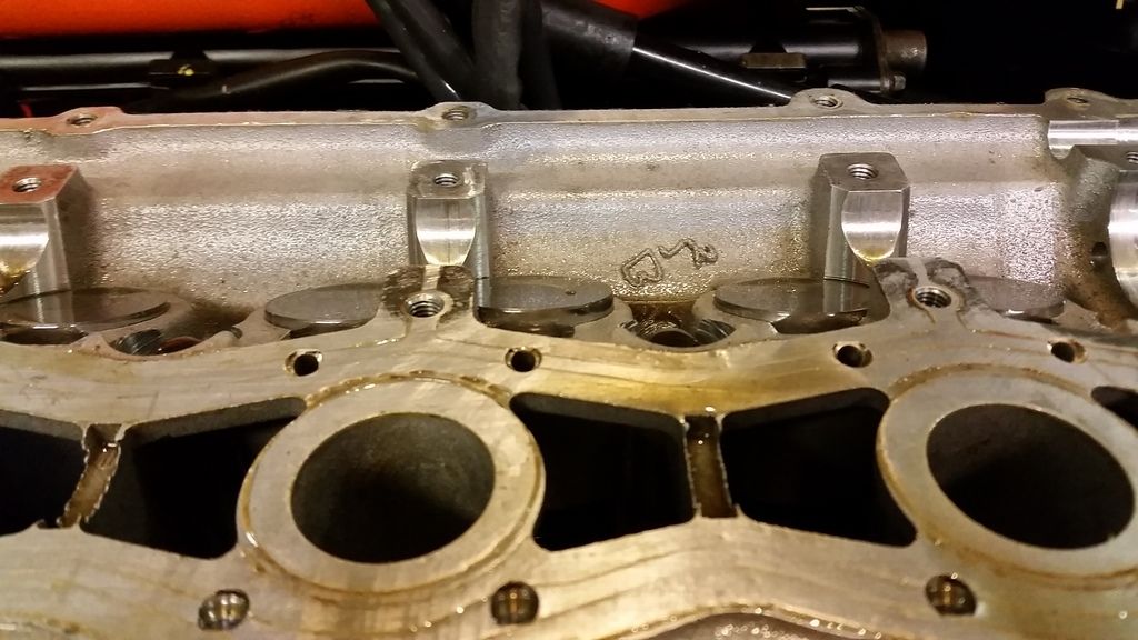
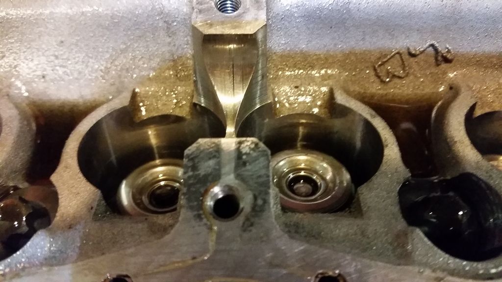
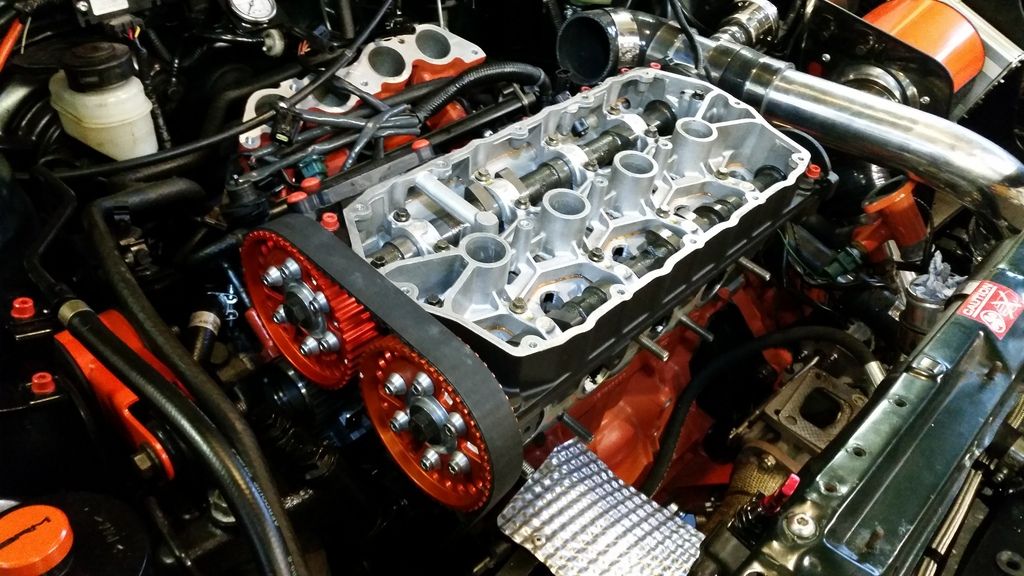
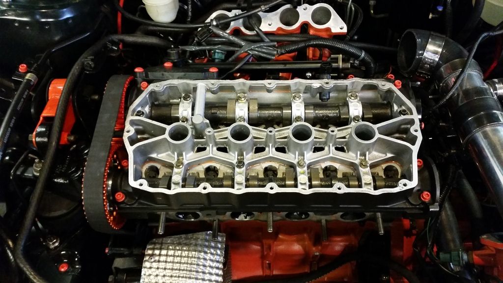
Looking at the head without the cams in and the problem is immediately obvious. One of the lifters on the inlet on cyl 3 is sitting high so with the cams torqued down its holding that valve open at all times. That'll do it!
Popped valve out and found this cheeky little blighter:
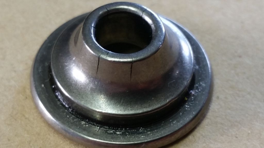
The valve spring cap has cracks all around it and this has let the valve slip off the collets but somehow had not come all the way off. Damn lucky as if it had completely failed, the valve would have dropped into the piston and pretty much destroyed the engine.
What caused this? Unknown although I suspect the vibration caused by the play in the VVC cams may have had something to do with it. Or maybe it was just bad luck?
Only thing for it is to replace all the caps with uprated steel caps to stop this happening again. Since I'm really not happy with the rattly VVC mechanisms, I'll also replace the variable valve system with a solid cam conversion kit supplied by Piper. Since I'm doing all that I'll replace the valve springs and have a look at upgrading the valves too.
Watch this space!
Got the Emerald installed with the supplied adapter loom for plug and play (although they forgot to install the boost control solenoid wiring so it had to go back) . They also supplied a 3 bar MAP sensor and a boost control solenoid. The first mapping will be at actuator pressure (about 8psi) so the solenoid is not doing anything at the moment. After run in I'll map for full power at around 16psi.
Filled up with Millers running in oil and coolant and she's ready to go. Disable injectors and ignition and turn over on the key to check it turns over and to get oil pressure. All fine so far. I'm getting nervous. I've never done this before. Maybe I should wait to get a couple of buddies round to act as extra pairs of eyes during this delicate time. I man up, plug everything back in, and turn the key.
BINGO! Fired up instantly!
A few tweaks of the Emerald to lower the Idle and then my eyes are trying to look at a million things at once! You really want minimal running at idle on a new build. The sooner you can get the engine under load and start bedding the rings in the better. So I checked for fuel, oil and coolant leaks and checked all temps and pressures were fine. Oil was struggling to get above 60 degrees C and it was clear the "thermostatic" oil cooler setup was over cooling (or the sensor was faulty). I had a couple of small coolant leaks that were sorted by nipping up clamps but other than that everything was fine.
And little vid of it running:
http://www.youtube.com/watch?v=O-zvICWkZ24
My initial reaction was "Jesus that top end is noisy". I assumed it was the VVC mechanisms as they are notoriously rattly and I've never heard a quiet setup - This is particularly bad though. That said, they hardly ever fail completely so my intention was to crack on with mapping and see how it goes. This, it turns out, was a mistake...
Rattling aside, I think it sounds great. The dump valve is a lot louder than I expected given its a recirculating system, but I kinda like it.
Time for mapping...
Booked in to see HT Racing who are based at Brands Hatch and had it trailered down there. Things were going well... At first...
A little vid of one of the runs:
http://www.youtube.com/watch?v=vGEZjrXCSKk
Then it all went a bit wrong...
We were almost done but then for no reason she developed a misfire at idle and low rpm. Lost compression in cylinder 3.
F#&k
Ok not the end of the world - might just be a sticky lifter. Definitely mechanical though so obviously I'm thinking "what have I done wrong?"!
Load back on the trailer and return home somewhat dejected with some further investigations to do.
I ran a compression leak down test. This is basically where you add compressed air to the cylinder with the piston at top dead centre on the compression stroke (so all the valves should be closed) and measure how quickly it leaks away. Around 10% would be normal on a new build and you want consistency across all cylinders. On cylinder 1,2, and 4 I had about 10%. On cylinder 3 I had 60%!
The clever bit about a leak down test is that you can tell what kind of problem you have by where the air is coming out. In my case it was rushing out of the throttle body, telling me I had an inlet valve stuck open. This could be a number of things so time to whip the head off.
Head off. Firstly, I obviously got a bad batch of valve stem oil seals as most of them are leaking! Pistons are coated although cleaned up nicely.


Looking at the head without the cams in and the problem is immediately obvious. One of the lifters on the inlet on cyl 3 is sitting high so with the cams torqued down its holding that valve open at all times. That'll do it!


Popped valve out and found this cheeky little blighter:

The valve spring cap has cracks all around it and this has let the valve slip off the collets but somehow had not come all the way off. Damn lucky as if it had completely failed, the valve would have dropped into the piston and pretty much destroyed the engine.
What caused this? Unknown although I suspect the vibration caused by the play in the VVC cams may have had something to do with it. Or maybe it was just bad luck?
Only thing for it is to replace all the caps with uprated steel caps to stop this happening again. Since I'm really not happy with the rattly VVC mechanisms, I'll also replace the variable valve system with a solid cam conversion kit supplied by Piper. Since I'm doing all that I'll replace the valve springs and have a look at upgrading the valves too.
Watch this space!
Edited by Stuballs on Friday 11th December 06:53
Edited by Stuballs on Monday 22 January 13:07
J4CKO said:
Very lucky, here is what happened when our old Fiat 500 dropped a valve.
http://retrorides.proboards.com/thread/105433
Jeez what a mess! What happened to it. http://retrorides.proboards.com/thread/105433
I'd have been tempted to whack a hayabusa engine in it. Maybe even turbo if for maximum giggles. Might have just found my next project...
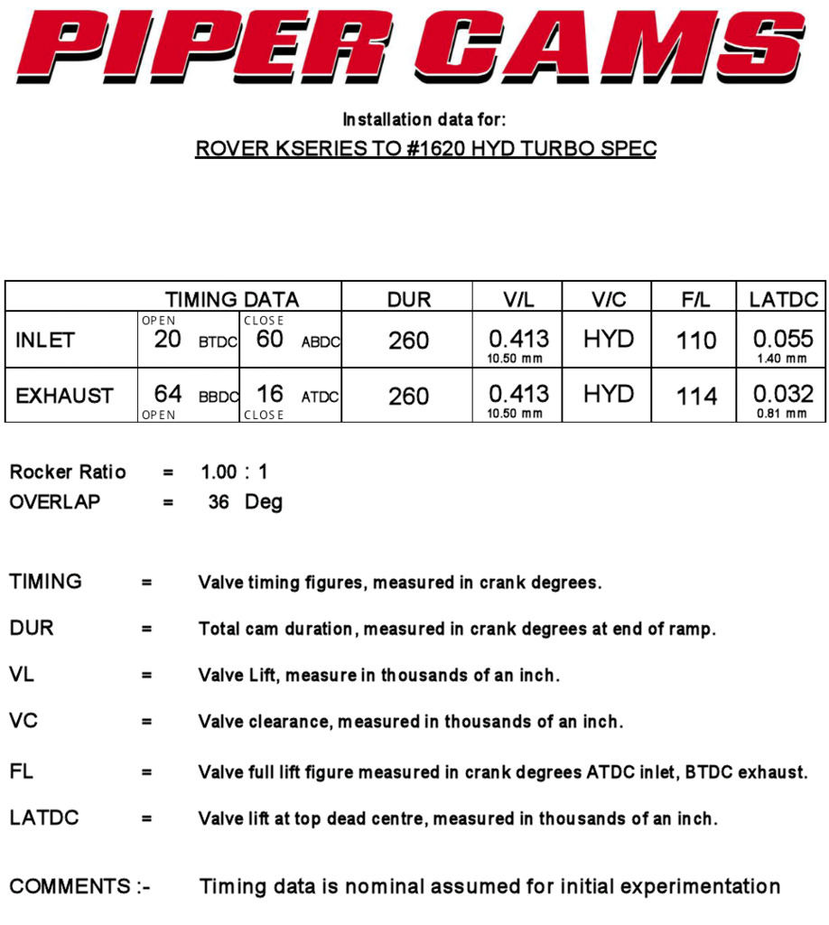
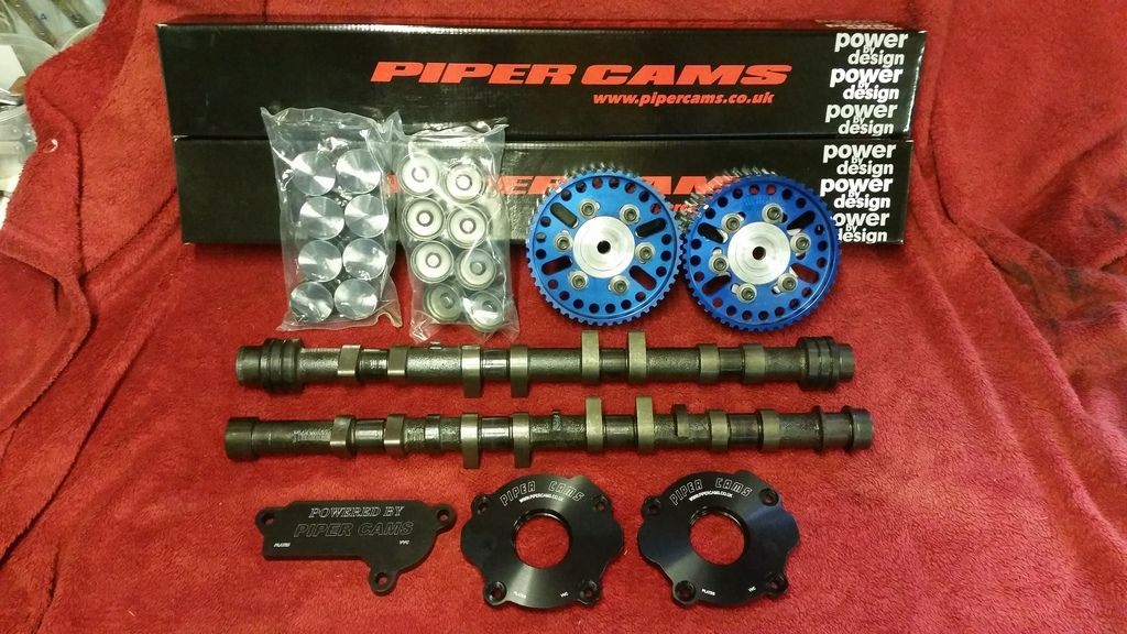
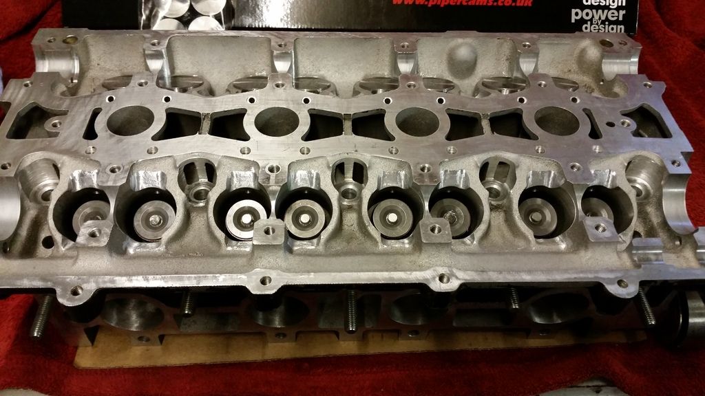
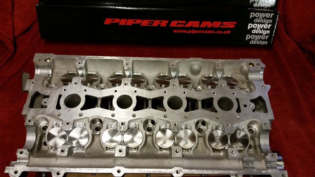
Piper sorted me out with some custom ground cams. They have fairly conservative duration given the forced induction with small turbo I'm running, but lift is a bit higher than stock. To compare against the VVC - they had 9.5mm lift with duration on the inlet ranging from 220 to 295 degrees.
Note the larger journals at each end of the inlet cam. This is why piper cams are the only option if ditching the split inlet cams the VVC system uses.
Also, the lack of position sensor pickup on the inlet means I have to revert to batch fuel injection. Shouldn't be a problem.
Spec:
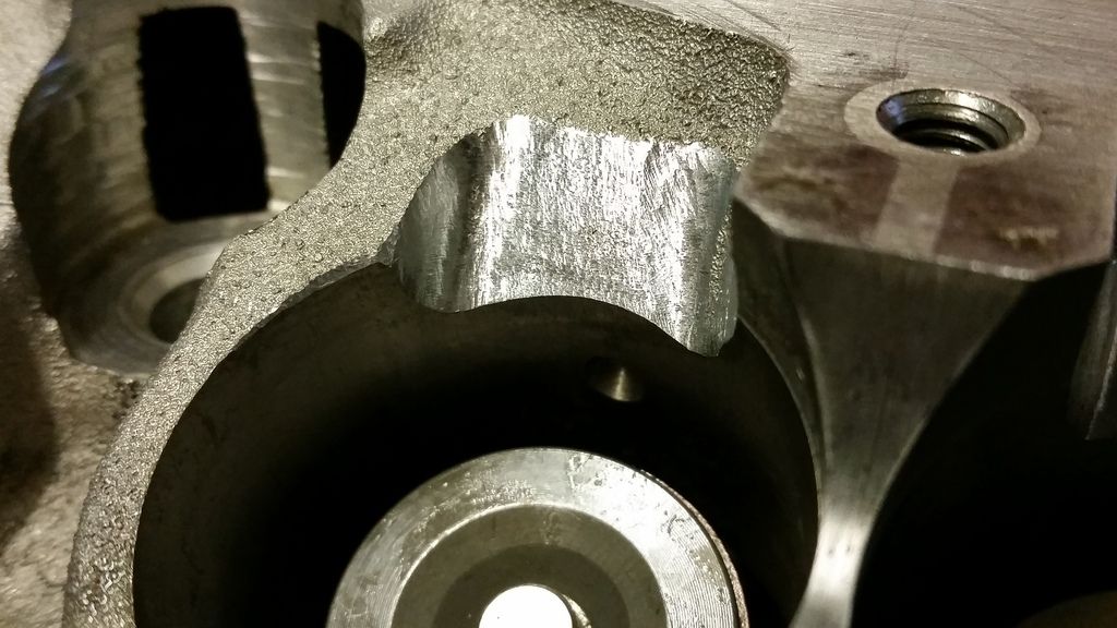
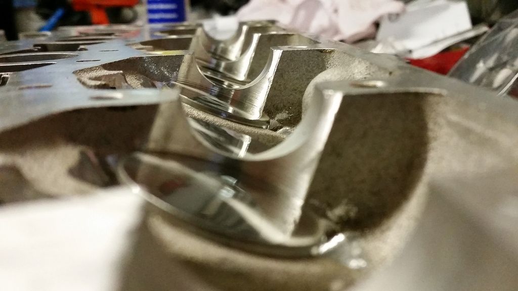
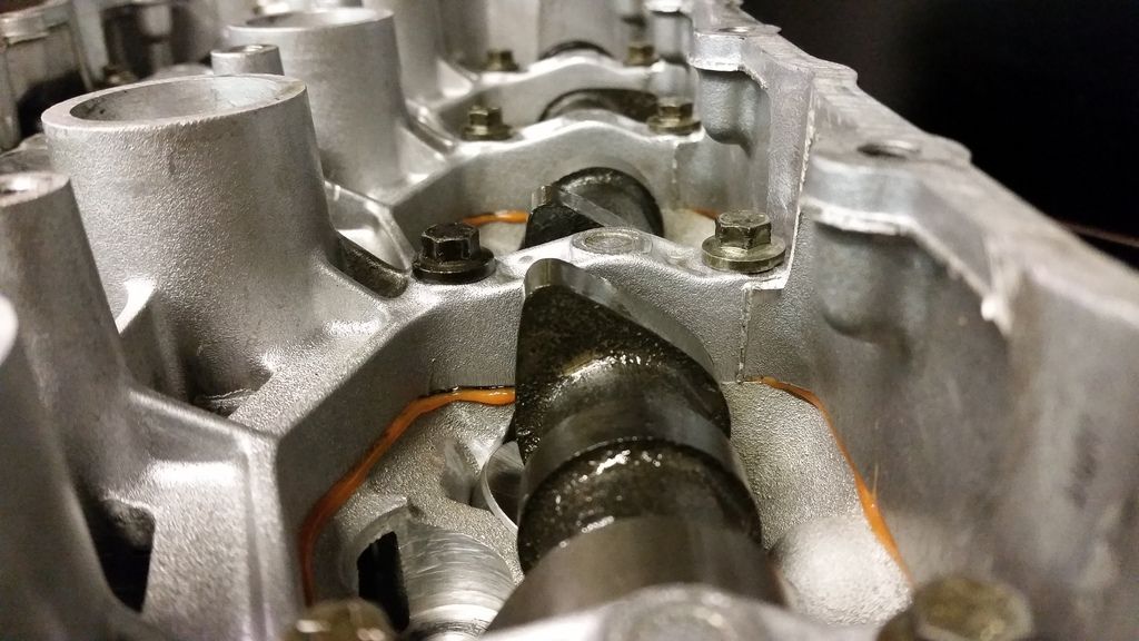
The extra lift and width of the cam lobes meant I had to fettle the head to provide adequate clearance!
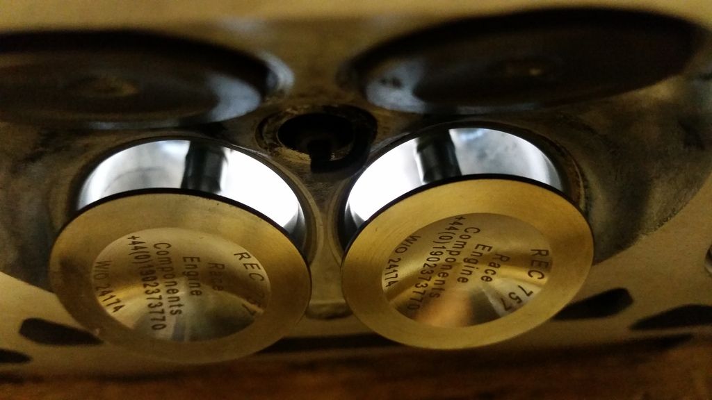
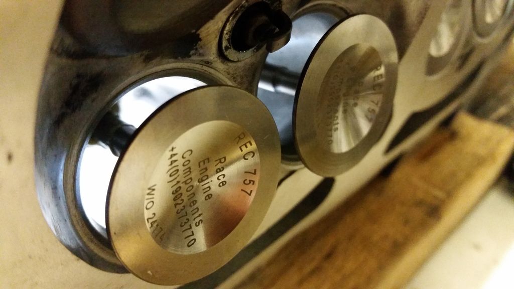
Uprated hydraulic followers from Piper going in.
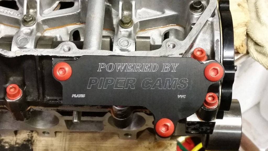
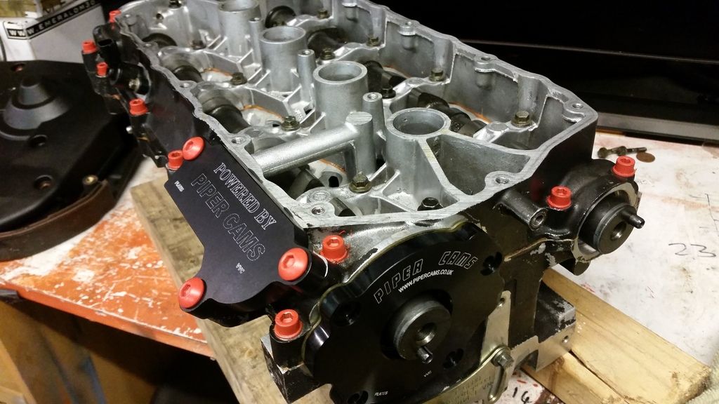
Cams and VVC blanking kit going in. The blanking kit is just three machined plates.
Next job is to get these timed in and finish putting her back together.
Note the larger journals at each end of the inlet cam. This is why piper cams are the only option if ditching the split inlet cams the VVC system uses.
Also, the lack of position sensor pickup on the inlet means I have to revert to batch fuel injection. Shouldn't be a problem.
Spec:
The extra lift and width of the cam lobes meant I had to fettle the head to provide adequate clearance!
Uprated hydraulic followers from Piper going in.
Cams and VVC blanking kit going in. The blanking kit is just three machined plates.
Next job is to get these timed in and finish putting her back together.
Edited by Stuballs on Monday 22 January 13:09
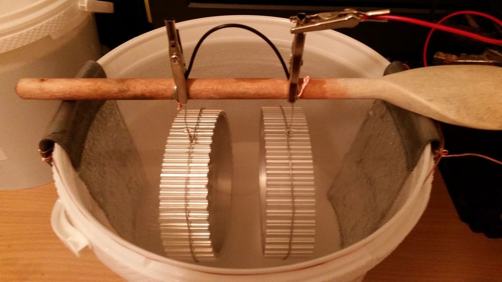
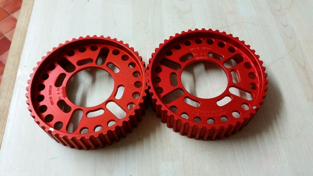
Mini update. I had a bit of time so I thought I'd change the colour of the vernier pulleys to match the rest of the engine bay and do something so they are on display.
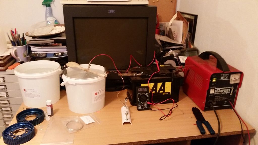
Anodising is actually a very simple process but involves some nasty chemicals so care must be taken. The part must be cleaned then stripped and etched in Sodium Hydroxide. Then it's just a case of rigging up a power supply and some electrodes in a solution of sulphuric acid electrolyte. I got everything in a kit off ebay and just used a12v car battery supported by a charger.
The setup :
Removing the existing anodising and etching the aluminum bits in Sodium Hydroxide:
Nice and clean and ready for anodising:
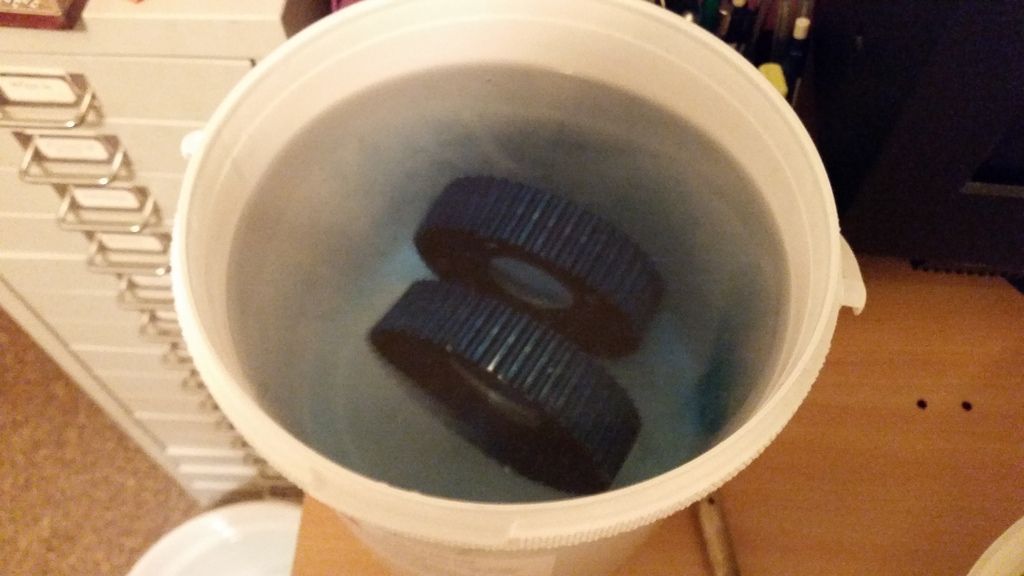
Process underway:
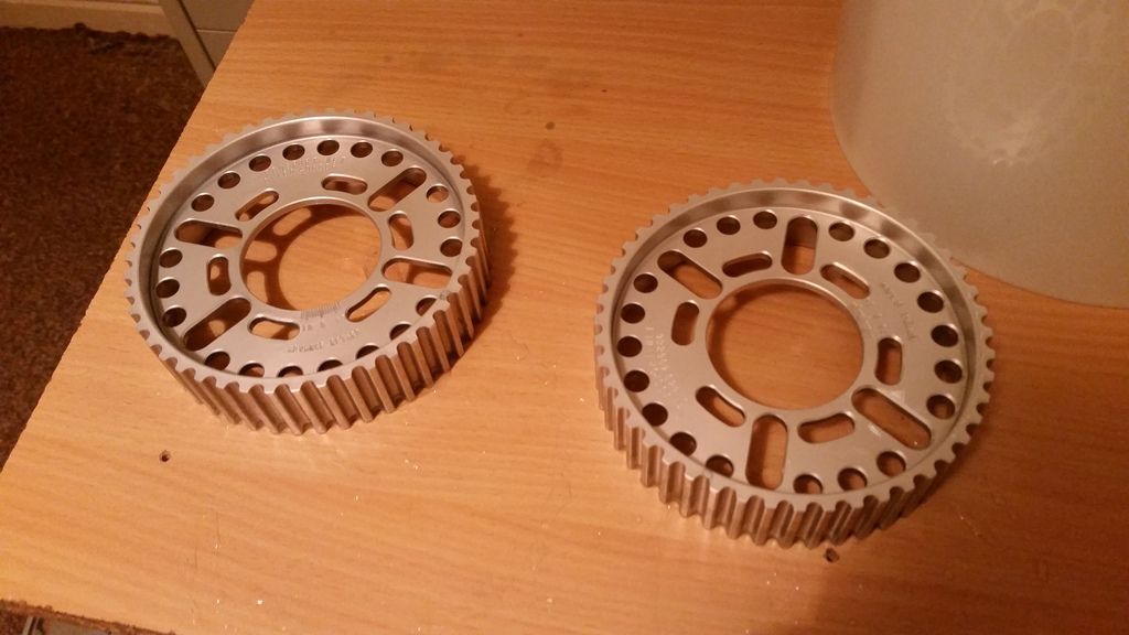
Once the anodising is complete (took about 45 minutes) it's just a case of soaking in dye for 20 minutes then sealing in boiling water for half hour.
This was the result:
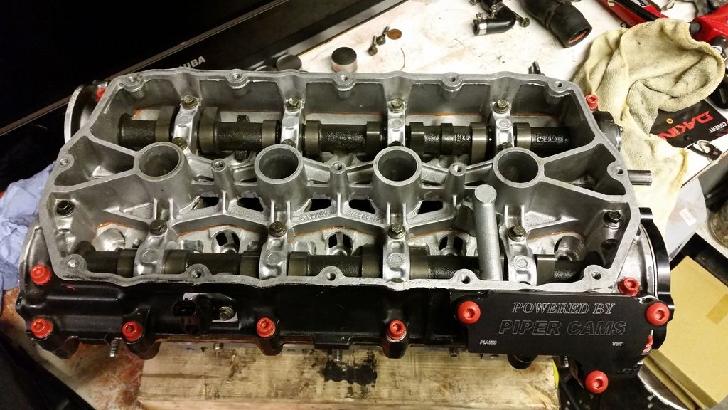
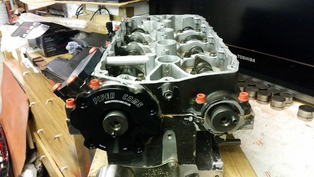
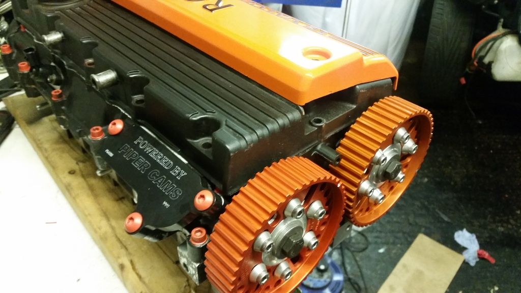
Fitted to the head which is now completely rebuilt and ready to refit to the car :
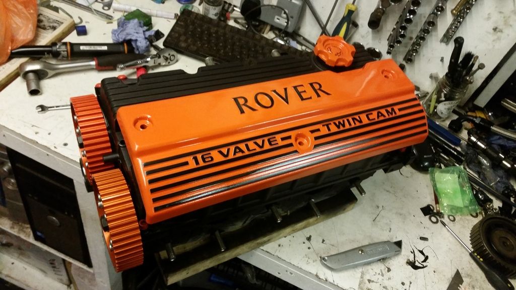
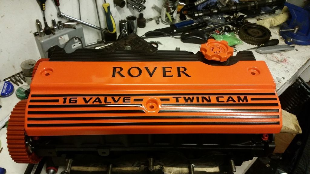
Mocked up with the new cam cover I acquired from an early mems3 setup so still had the "Rover" emblem. Very hard to come by:
Next job is just to pop this back on, get the cams properly timed in, then fire it up and see what happens!
Anodising is actually a very simple process but involves some nasty chemicals so care must be taken. The part must be cleaned then stripped and etched in Sodium Hydroxide. Then it's just a case of rigging up a power supply and some electrodes in a solution of sulphuric acid electrolyte. I got everything in a kit off ebay and just used a12v car battery supported by a charger.
The setup :
Removing the existing anodising and etching the aluminum bits in Sodium Hydroxide:
Nice and clean and ready for anodising:
Process underway:
Once the anodising is complete (took about 45 minutes) it's just a case of soaking in dye for 20 minutes then sealing in boiling water for half hour.
This was the result:
Fitted to the head which is now completely rebuilt and ready to refit to the car :
Mocked up with the new cam cover I acquired from an early mems3 setup so still had the "Rover" emblem. Very hard to come by:
Next job is just to pop this back on, get the cams properly timed in, then fire it up and see what happens!
Edited by Stuballs on Monday 22 January 13:12
Ive said:
Stu,
Similar build to my supercharged K. Steel rods, JDM pistons, Westwood lines, Mahle bearings,.
A note regarding cams. Newman also make cams with the bigger journals for the VVC head. I use the Newman ph2 with very similar specs on a blanked VVC160 head. 10.15mm lift and 260 deg duration. Your's got a little more lift with 10.5mm. :-)
Marko
Sounds an interesting build. I contacted Newman and Kent cams and both told me they didn't make VVC journal cams. Guess I got some bad info from Newman.Similar build to my supercharged K. Steel rods, JDM pistons, Westwood lines, Mahle bearings,.
A note regarding cams. Newman also make cams with the bigger journals for the VVC head. I use the Newman ph2 with very similar specs on a blanked VVC160 head. 10.15mm lift and 260 deg duration. Your's got a little more lift with 10.5mm. :-)
Marko
I'm happy with what i ended up with.
Update time! Fitting the head and timing the new cams in:
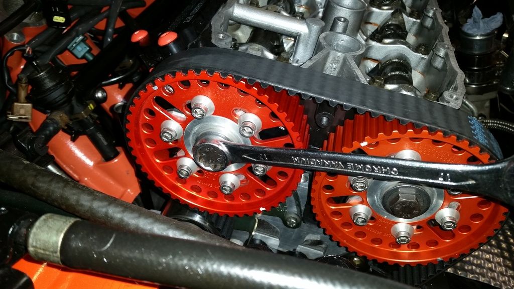
I've already got the cams installed with the vernier pulleys. 10.5mm lift over the standard 9.5mm:
Easiest way to time the cams correctly is by reference to lift at Top Dead Centre. Dave Andrews' k-series engine page has a very useful step by step guide on how to do this.
First, you need identify when cyl 1 and 4 are at TDC. There are a number of ways to do this. Since I had the head off, I just did it by eye. It took a lot of patience as there is a dwell point right at the top where the piston hardly moves. If the head is on, you could either rig up a dial gauge with a long probe down through the spark plug hole, or use a long bolt (like a head bolt) down through the plug hole and do it by eye. I made up a pointer for easy reference:
Before the head went on, I set the bottom end to exactly 90 degrees Before Top Dead Centre:
I then used the timing marks from the stock pulleys for 90BTDC to make equivalent marks on the vernier pulleys, so the timing is as close to correct as possible. Head on and cambelt refitted:
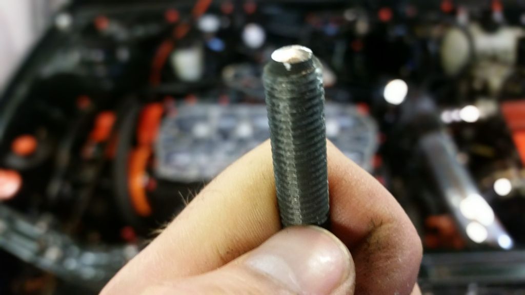
A quick point on head bolts. It is possible for the bolts to be too long and foul the sump. This obviously affects the clamping on the head gasket and it's believed to be one of the contributing causes of head gasket failure on the k-series, expecially if using cheaper aftermarket bolts.
As before, I'm using the 5-layer n-series gasket but this time I'm using it with the supplied higher grade 10.9 bolts (which require a modified tightening procedure of 20nm + 180° + 135°). These bolts were very slightly longer than the old ones I took out (which being used stretch bolts had probably stretched slightly anyway). To be safe, I shaved a couple of mm from the tip of each bolt:
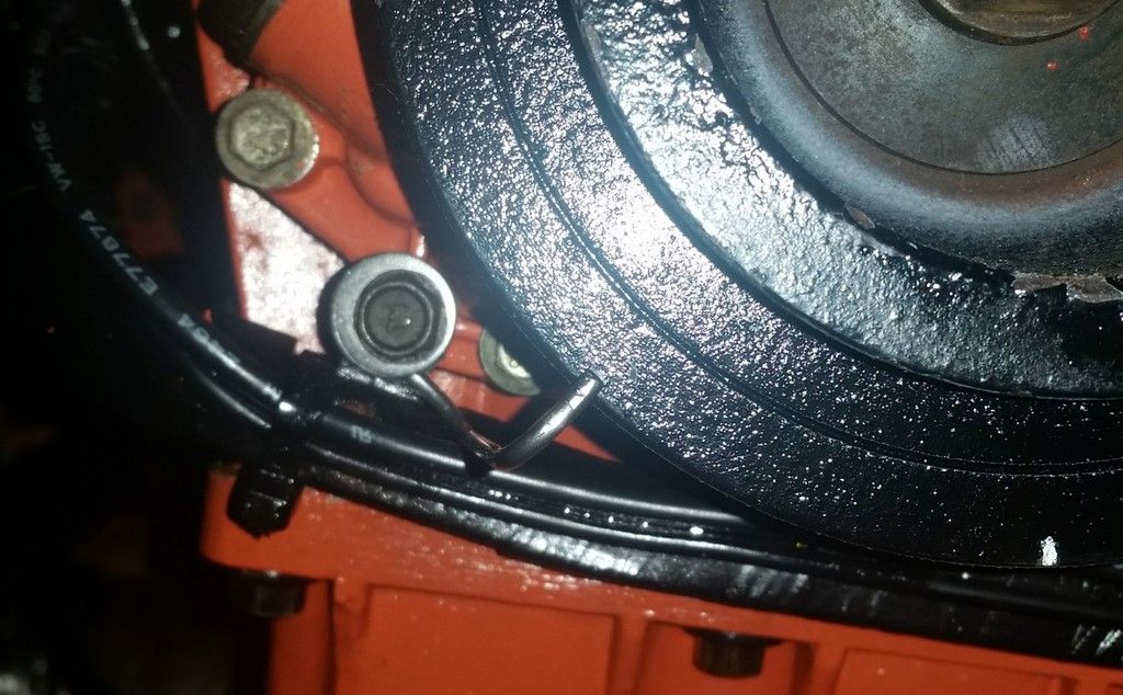
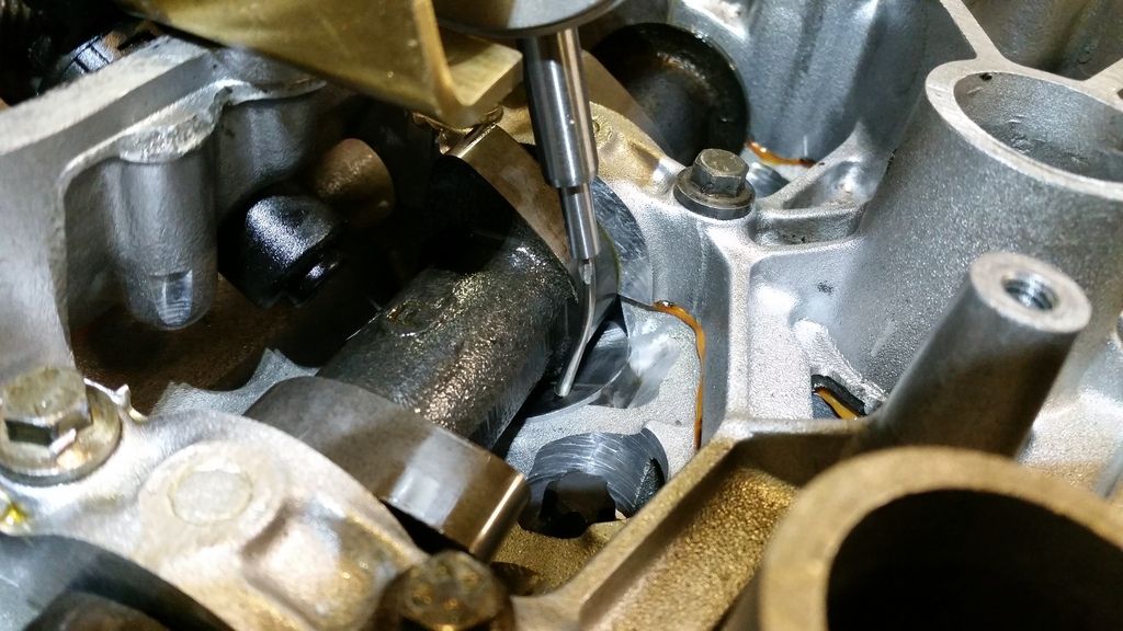
Rigging up a dial Gauge using brackets I had made up a while back to Dave Andrews design. Used some 2.4mm tig wire screwed into the tip of the gauge and bent to shape.
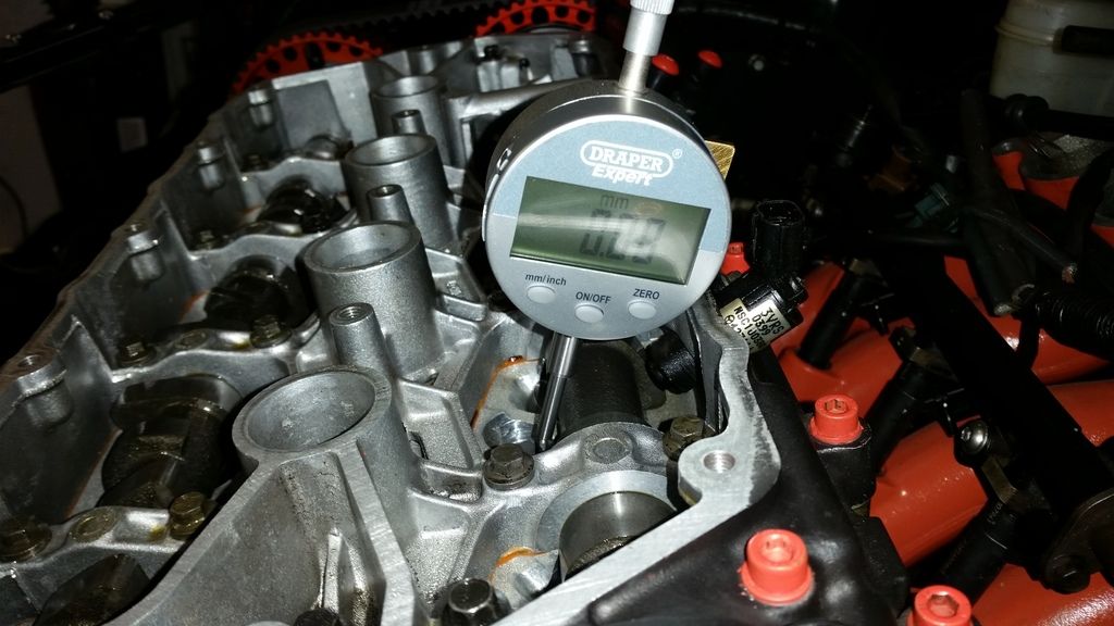
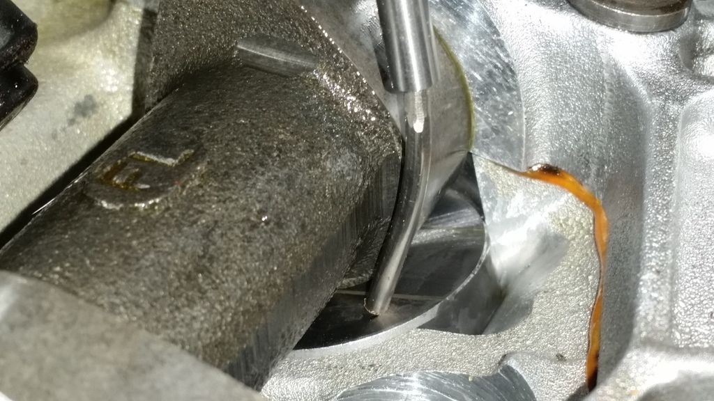
Very tricky getting the gauge in the right place with the gauge tip on the lifter but not fouling the camshaft:
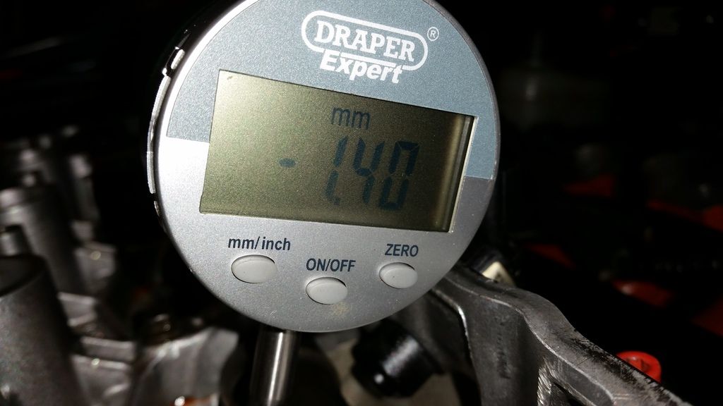
Engine set back to TDC. Then loosened the clamp bolts on the pulley and adjusted the cam to give the correct lift at TDC as specified in the spec sheet. On the inlet, this is 1.4mm:
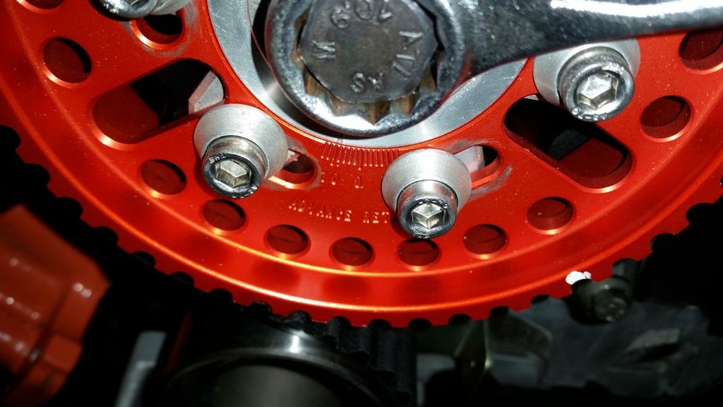
Bang on!
Actually wasn't that simple at all! Every time you clamp up the vernier clamp bolts and turn the engine over a couple of times it changed! It took at least 5 iterations to get it right. Got there in the end though!
One last turn over by hand to make sure nothing collides. I then spent the next few hours putting everything back together and refilling fluids.
Crunch time. One last check over everything. Unplug injectors for a test turnover. Turn the key and...
Flat battery!
I rigged up a spare with enough charge to turn over and check I have oil pressure. All good.
A quick bit of breakfast then I'll fire up this afternoon.
I've already got the cams installed with the vernier pulleys. 10.5mm lift over the standard 9.5mm:
Easiest way to time the cams correctly is by reference to lift at Top Dead Centre. Dave Andrews' k-series engine page has a very useful step by step guide on how to do this.
First, you need identify when cyl 1 and 4 are at TDC. There are a number of ways to do this. Since I had the head off, I just did it by eye. It took a lot of patience as there is a dwell point right at the top where the piston hardly moves. If the head is on, you could either rig up a dial gauge with a long probe down through the spark plug hole, or use a long bolt (like a head bolt) down through the plug hole and do it by eye. I made up a pointer for easy reference:
Before the head went on, I set the bottom end to exactly 90 degrees Before Top Dead Centre:
I then used the timing marks from the stock pulleys for 90BTDC to make equivalent marks on the vernier pulleys, so the timing is as close to correct as possible. Head on and cambelt refitted:
A quick point on head bolts. It is possible for the bolts to be too long and foul the sump. This obviously affects the clamping on the head gasket and it's believed to be one of the contributing causes of head gasket failure on the k-series, expecially if using cheaper aftermarket bolts.
As before, I'm using the 5-layer n-series gasket but this time I'm using it with the supplied higher grade 10.9 bolts (which require a modified tightening procedure of 20nm + 180° + 135°). These bolts were very slightly longer than the old ones I took out (which being used stretch bolts had probably stretched slightly anyway). To be safe, I shaved a couple of mm from the tip of each bolt:
Rigging up a dial Gauge using brackets I had made up a while back to Dave Andrews design. Used some 2.4mm tig wire screwed into the tip of the gauge and bent to shape.
Very tricky getting the gauge in the right place with the gauge tip on the lifter but not fouling the camshaft:
Engine set back to TDC. Then loosened the clamp bolts on the pulley and adjusted the cam to give the correct lift at TDC as specified in the spec sheet. On the inlet, this is 1.4mm:
Bang on!
Actually wasn't that simple at all! Every time you clamp up the vernier clamp bolts and turn the engine over a couple of times it changed! It took at least 5 iterations to get it right. Got there in the end though!
One last turn over by hand to make sure nothing collides. I then spent the next few hours putting everything back together and refilling fluids.
Crunch time. One last check over everything. Unplug injectors for a test turnover. Turn the key and...
Flat battery!
I rigged up a spare with enough charge to turn over and check I have oil pressure. All good.
A quick bit of breakfast then I'll fire up this afternoon.
She lives! (again!)
Fired right up on the key despite this map being way out for these cams. Idle was obviously an issue.
There then followed a very nervous 20 minutes running at 2k - 2.5krpm to bed the cams in. During this time I checked for leaks and generally panicked and worried at every little noise. The top end is noisier than expected. Part of this I think is down to the low duration/high lift combo of these cams resulting in a high ramp. A lot of it, however, is down to a leaking exhaust manifold gasket!
Need to get booked in for mapping asap now!
Thanks guys.
Ticking is defo mostly the exhaust manifold. Nipped it up and started from cold and noise completely gone. Started to come back as it warmed up so will change it.
I'd forgotten how loud the top end was on the old VVC setup. Listen to the rattle right at the end!
https://youtu.be/O-zvICWkZ24
The engine defintely revs up quicker with these new cams. Sounds really good. Can't wait to get it mapped.
RemyMartin said:
Can I say....ITB?
That really would be something but would be overkill on this build I think. If it was a track toy or race car I would consider it. Incidentally I know someone who had recently looked into fitting Jenveys to a k-turbo. Jenvey were interested in helping put something together but it's for a time attack elise and only if they aim for 500bhp plus.On my humble road car I'd be spending a lot of money to get something less driveable on the road.
Gods imagine the sound though!
For peace of mind, in advance of the mapping, I thought I would rig myself up a boost leak tester. The boosting and dumping sound doesn't sound the same as it did before the head change and I've got some time while I wait for the mapping so it's worth doing.
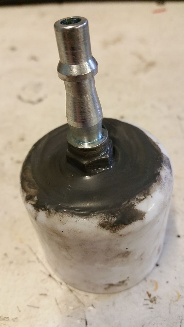
Pretty simple concept. Feed controlled compressed air to the intake and listen for leaks.
I basically bodged a male quick-connect compressor fitting into an aerosol lid that fit my inlet pipework perfectly. Because Rover.
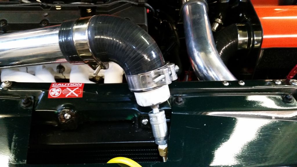
Started off with 5psi from the regulated side of my compressor. The result was frankly astounding.
The big leak that was immediately obvious was where the brake servo pipe meets the inlet manifold. Air was literally pouring out! Closer inspection revealed a missing o-ring! Luckily I had a spare plastic mpi manifold that users the same fittings so that was an easy fix.
Next up were 4 separate leaks from various boost clamps primary of which was where the inlet pipework meets the throttle body. These were sorted with tightened/upgraded clamps.
Finally, the throttle body itself has a small leak from where the cable retaining body fits on. I guess it's a failed seal what's the shaft enters the throttle body. Don't know if that can even be changed but easist fix is just to change the throttle body. It's a really small leak and barely noticeable below 15 psi so might wait until after first mapping session.
Tested up to 20 psi and no other leaks. Glad I took the time to do this. Roll on mapping!
Pretty simple concept. Feed controlled compressed air to the intake and listen for leaks.
I basically bodged a male quick-connect compressor fitting into an aerosol lid that fit my inlet pipework perfectly. Because Rover.
Started off with 5psi from the regulated side of my compressor. The result was frankly astounding.
The big leak that was immediately obvious was where the brake servo pipe meets the inlet manifold. Air was literally pouring out! Closer inspection revealed a missing o-ring! Luckily I had a spare plastic mpi manifold that users the same fittings so that was an easy fix.
Next up were 4 separate leaks from various boost clamps primary of which was where the inlet pipework meets the throttle body. These were sorted with tightened/upgraded clamps.
Finally, the throttle body itself has a small leak from where the cable retaining body fits on. I guess it's a failed seal what's the shaft enters the throttle body. Don't know if that can even be changed but easist fix is just to change the throttle body. It's a really small leak and barely noticeable below 15 psi so might wait until after first mapping session.
Tested up to 20 psi and no other leaks. Glad I took the time to do this. Roll on mapping!
Shadow R1 said:
That's a good idea, saved loads of time at the mapping chasing faults.
The T5 had a boost leak, they used a smoke machine to pressurise the system, then could see where it was coming from, spilt hose but could only see once it was pressurised.
Yeah some clever bits of kit our there. Fortunately my leaks are so bad I could just hear them!The T5 had a boost leak, they used a smoke machine to pressurise the system, then could see where it was coming from, spilt hose but could only see once it was pressurised.
I think it's positive it that even with these leaks, dodgy VVC mechanisms and an incomplete map, it was still making 190bhp at 8psi.
Can't wait to see what it's capable of when everything is working!
Tahiti said:
I have just read the whole thread. Love the project. I had a BRM that was unfortunately Cat C'd and scrapped at about 5 years old. I loved the thing. I did some simple stuff like a 52mm TB, filter and exhaust but it was a very capable car out of the box, and it surprised a few people.
The seats were among the least supportive/most slippery seats I've ever been in though. With 300BHP, that's going to be fun!
Thanks! The seats were among the least supportive/most slippery seats I've ever been in though. With 300BHP, that's going to be fun!
As standard they are a quick car. Lots of fun and the modest power let's you thrash it and still be at sensible speeds. It makes for a very rewarding drive and there's a lot to be said for that. The chassis is impressive too. I do worry I may have compromised that somewhat with my mods but nothing I have done is irreversible. Ultimately I may go for road-biased coilovers.
You're right about the seats. On a track day I would be fighting to stay in the seat. Should be fine on the road though. The red leather interior is so important to the character of the car but I do wonder if a bucket seat could be trimmed in similar quilted red leather....
Mapping booked for next Monday. Just have to change the oil and filter and change the exhaust manifold gasket. I'll also swap out the leaky throttle body if the replacement arrives in time. It would be nice to know I have zero boost leaks going into the mapping.
227bhp said:
I bet they aren't easy to set up though.
I've long since wondered about these pressure testers, they fall down because you've always got an inlet valve open so the air just rushes through and it won't pressurise. Did you pay much attention to where the cams were positioned or just blow so much air in and had such big leaks it showed up anyhow?
Well spotted! I set the engine to 90 degrees btdc so that each cylinder would, at most, either have inlet or exhaust valves open but not both. With an inlet open you do have the potential for tiny leakage past the rings but it's minimal and not enough to stop you finding boost leaks.I've long since wondered about these pressure testers, they fall down because you've always got an inlet valve open so the air just rushes through and it won't pressurise. Did you pay much attention to where the cams were positioned or just blow so much air in and had such big leaks it showed up anyhow?
Another option is to only test up to the throttle body, and blank off the inlet there. But all my leaks were after the throttle body so that would not have helped me!
Gassing Station | Readers' Cars | Top of Page | What's New | My Stuff