Rover 200 BRM - 1.8 K-Series turbo project
Discussion


Stu, glad you have come round to posting a thread on this build. I've enjoyed reading these first few pages and find it a most educating read. The thing I enjoy most is that we see the whole journey of the engine build which can sometimes be left out and it's hard to get a true sense of labour. As for any potential negative comments, this is a site for pure motor enthusiasts which you clearly are, I respect anyone who can picture the end result, source the parts and build from scratch any engine. Talk is very cheap on forums! So hats off mate.
Look forward to the updates.
Andy
Look forward to the updates.
Andy
Getting rare now, 174 left apparently, from 795.
My uncle still has one, has had it for like 15 years, it got a new engine earlier this year.
There was a fantastc 25 rally car at the Event City show this year, properly bats t fast, best thing there apart from the Can AM Frenza, couldnt find the ROver but here is the Firenza and realised yours truly appears in the video.
https://www.youtube.com/watch?v=4WduQiFmpIQ
My uncle still has one, has had it for like 15 years, it got a new engine earlier this year.
There was a fantastc 25 rally car at the Event City show this year, properly bats
t fast, best thing there apart from the Can AM Frenza, couldnt find the ROver but here is the Firenza and realised yours truly appears in the video.https://www.youtube.com/watch?v=4WduQiFmpIQ
Thanks guys. 
Yeah not many on the road anymore and value is slowly increasing as a result. I think I got mine when the market was at its lowest and there were over 400 still taxed then. Problem is that almost any collision will write one off. And those that don't go out to accidents get eaten by rust!
Yeah not many on the road anymore and value is slowly increasing as a result. I think I got mine when the market was at its lowest and there were over 400 still taxed then. Problem is that almost any collision will write one off. And those that don't go out to accidents get eaten by rust!
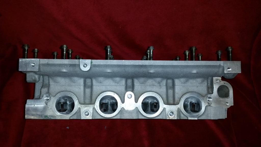
Head!
Cylinder head, that is. The original plan was to keep the Variable Valve Timing to see how it coped with forced induction. The VVC only works on the inlet and varies the duration from 220 degrees to 295 degrees as rpm increases. It does this by slowing the cam down as the lobe opens the valve. It's a clever but fragile system. They are always loud and most VVCs sound a little bit diesel! That said, it works and they are a hoot to drive.
My turbo is probably too restrictive for the big overlap the VVC produces at full duty, but since I can control it with the Emerald ECU I figured I could just keep it at low duration if it caused problems. The intention was to tune it for optimum results. It didn't quite work out and I went in a different direction in the end. More on that later. For now, I'll share what I did anyway.
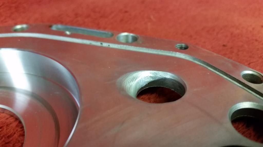
I had a nightmare finding a good VVC head that hadn't been skimmed to hell and back. Unfortunately a lot of VVC engines have had hgf which led to overheating and a softening of the head. This causes the liners to indent the head so I was looking for one without those telltale sunken areas around the fire rings.
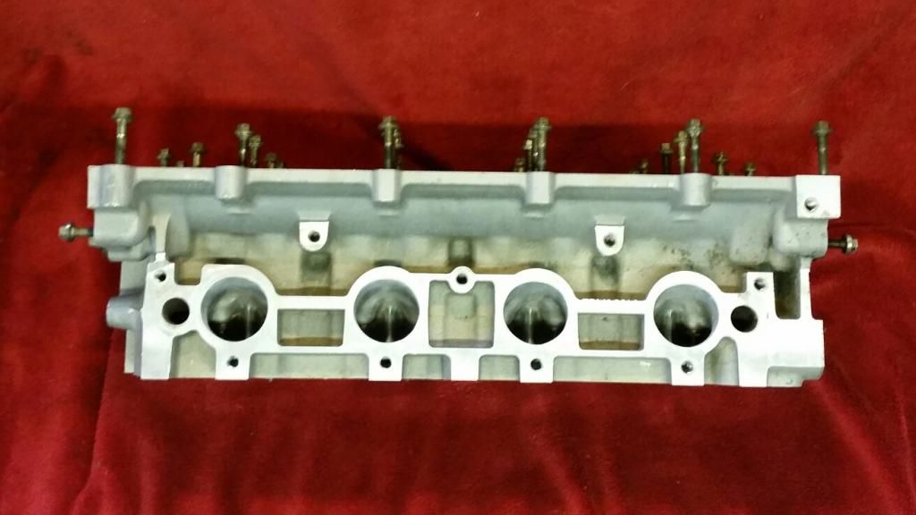
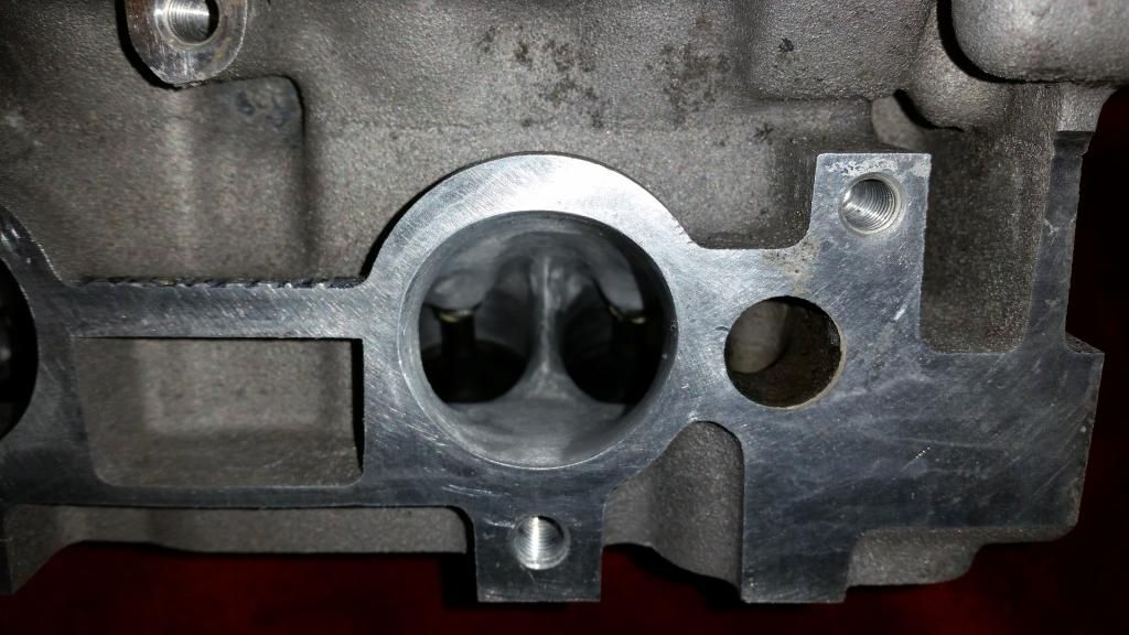
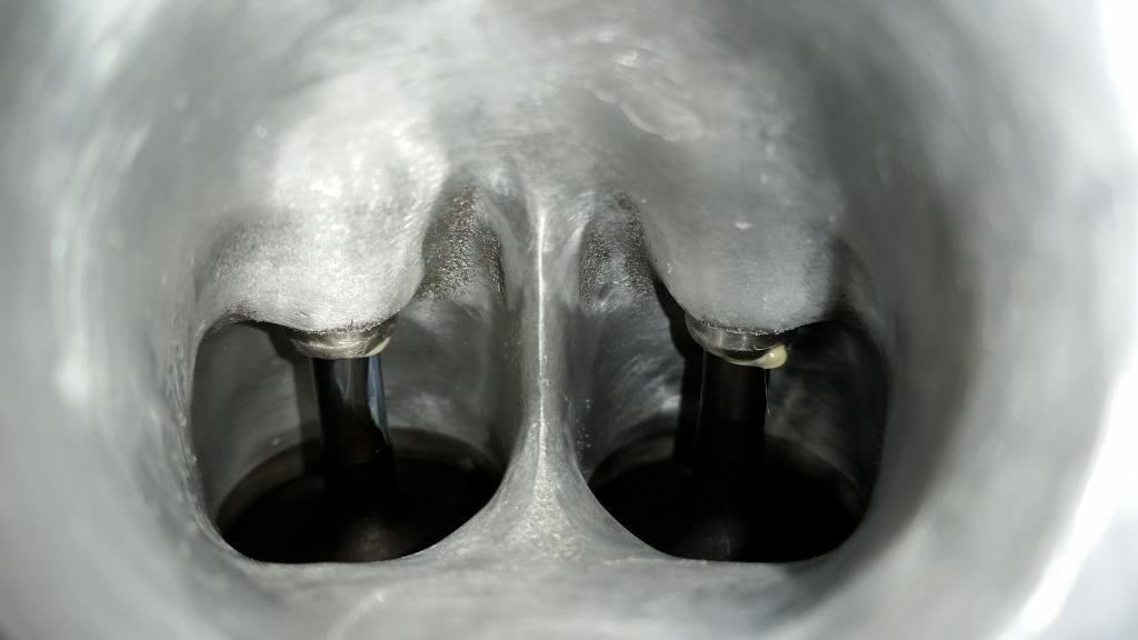
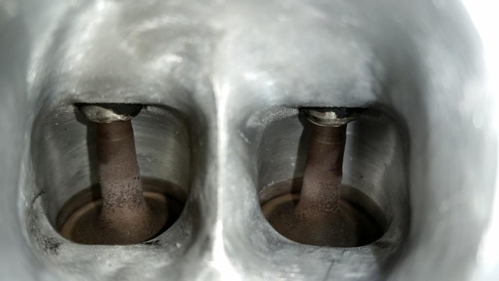
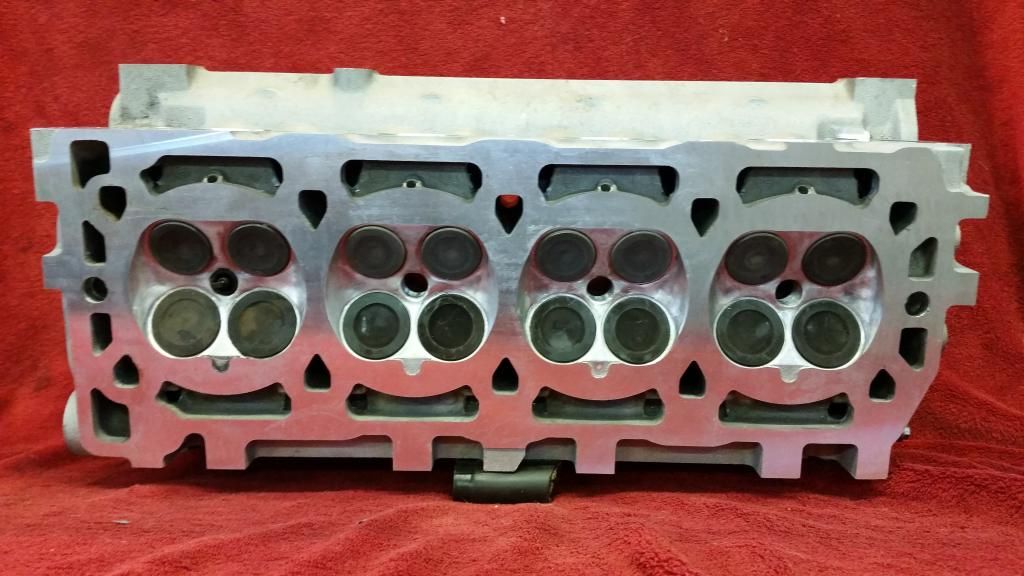
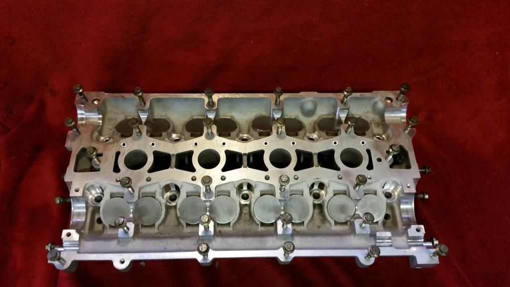
The head I ended up using was from a Caterham. It was basically good and had only ever had a light skim. I dropped it off for a quick porting with TDR motorsport by Brands Hatch who I know through the BRM forum. They opened everything up for improved flow and matched the ports to inlet and exhaust manifolds. You'll see a fair bit of meat was left on the valve guide bosses to help heat dissipation.
Before:
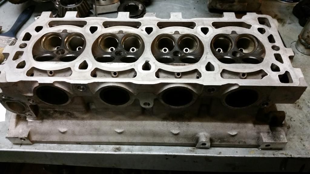
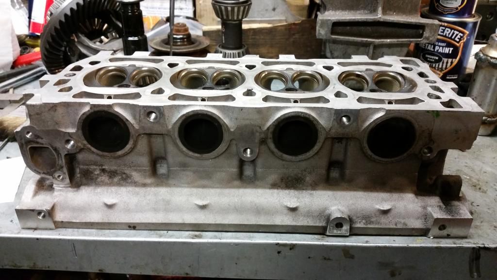
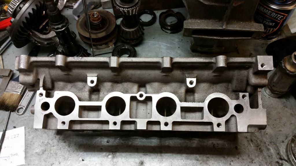
After:
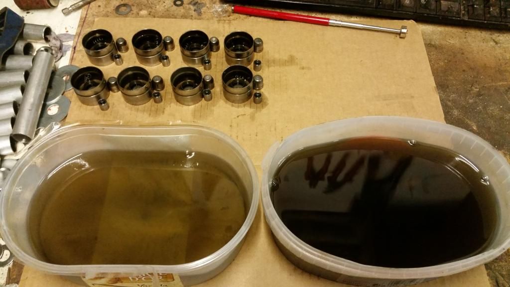
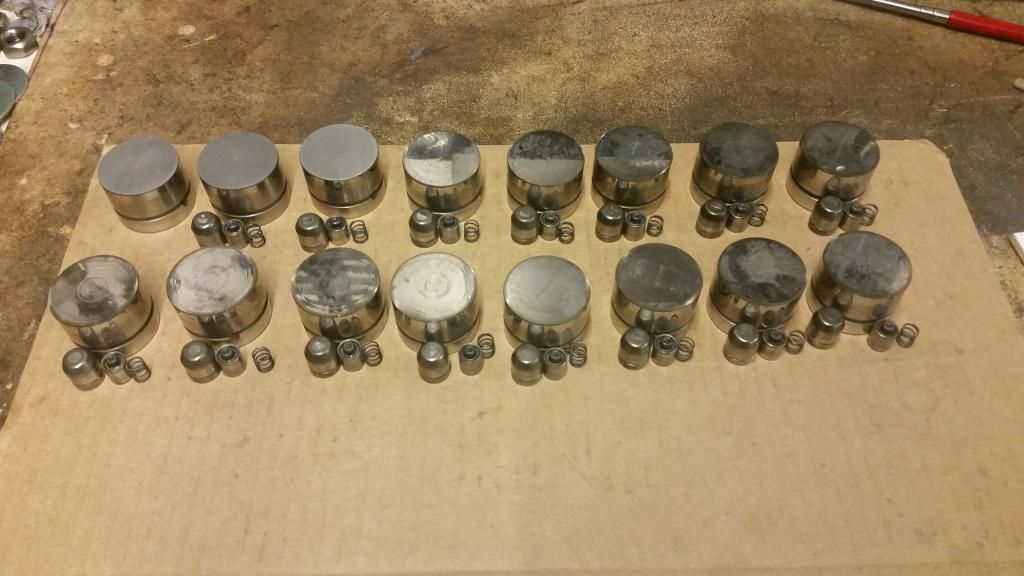
I then turned my attention to the lifters. They weren't too bad but the cam-lobe surfaces had some scuffs so I planished them with various grades of wet and dry.
Cleaning:
Planishing:
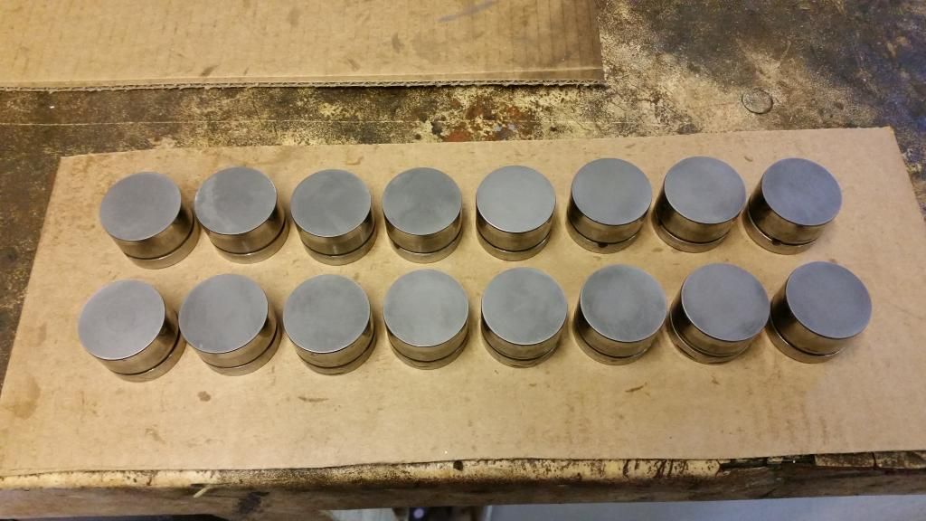
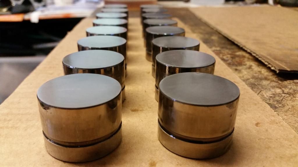
All in!
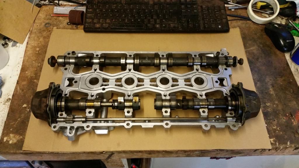
Now to the VVC mechs. I had thought to simply transfer the VVC gear from one cam ladder into the other. Unfortunately they needed synching. An hour of reading later and I had it sussed - whilst daunting, it's actually not that difficult and you just have to be patient and careful not to let the mechanisms fall apart while you're handling them! If that happens you're in a world of pain and there are dozens of parts.
I elected to use the SAIC developed so-called "n-series" head gasket. This was quite literally marketed by x-part as the ultimate fix for k-series head gaskets and is comprised of the SAIC developed gasket, grade 10.9 head bolts (with a slightly revised tightening procedure) and the stiffer oil rail.
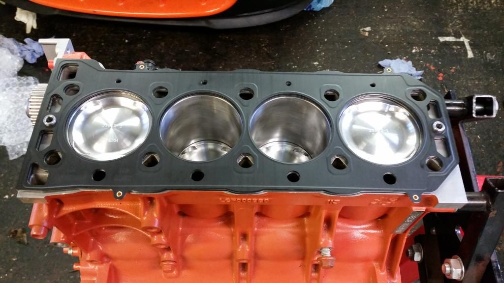
Many layers:
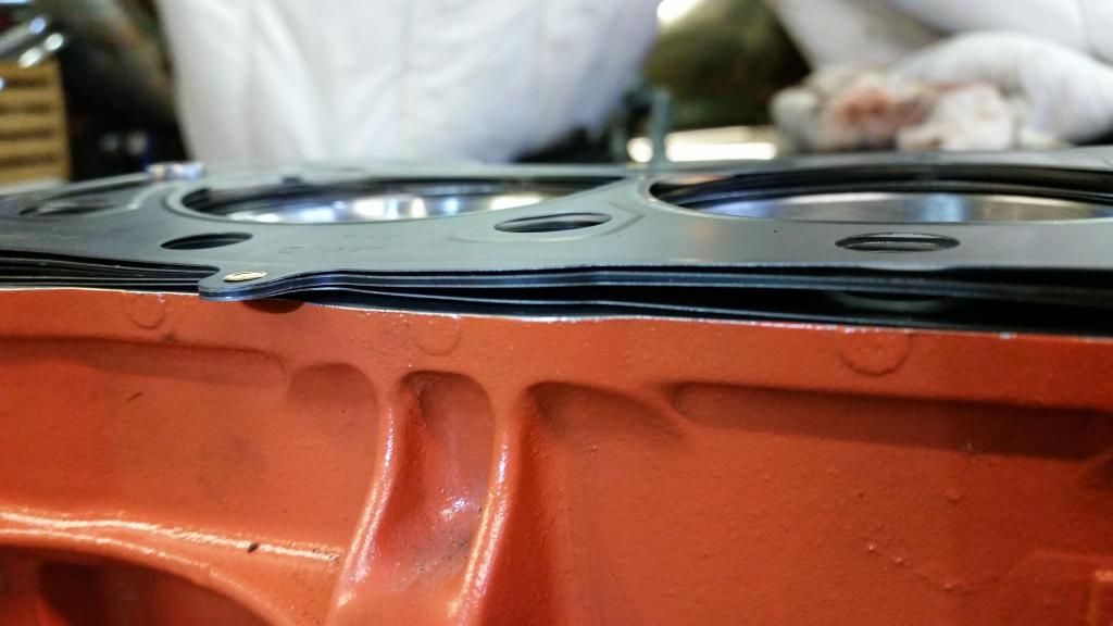
Head on!!
The gasket compressed to 2mm with the head torqued down. I re-measured the volume of the combustion chamber post porting and skim and I should now have a static compression ratio of almost exactly 9:1. which is what I wanted.
Also took care of a few other bits
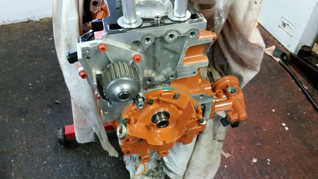
Oil pump modified with radius'd edges for improved flow and fitted. I actually did this to the old one then decided to just replace it with new. So had to do it all again (only better - of course!). Naturally, I painted it orange! Also fitted water pump. I am as-yet undecided on the orange bolts - you'll not see these ones anyway but I have a whole engine bay kit - If they look gash I'll use normal stainless.
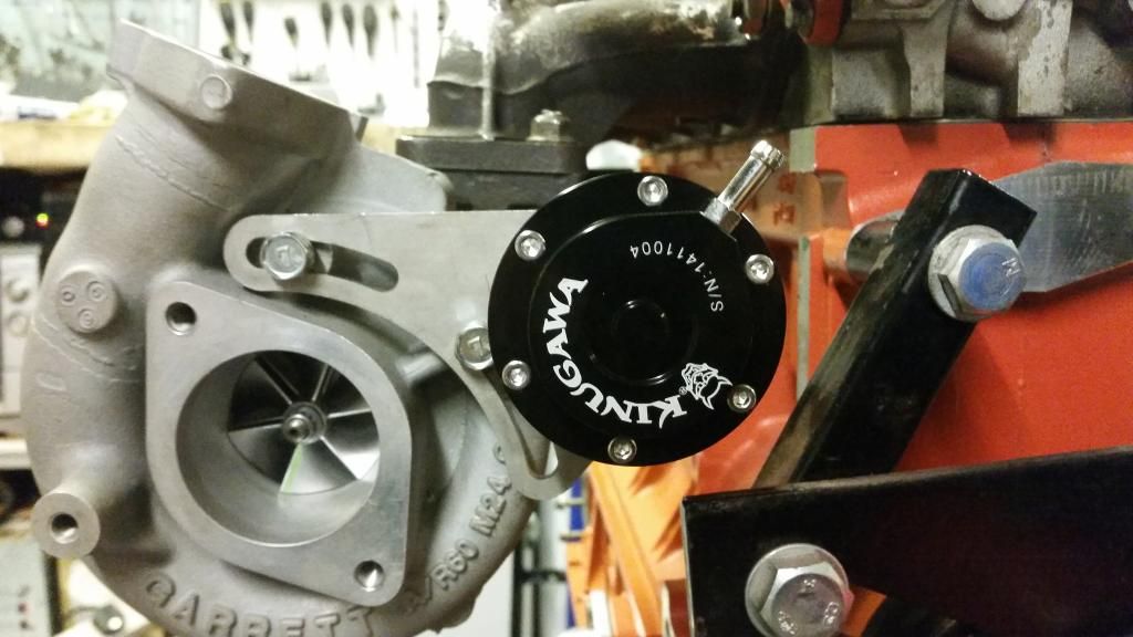
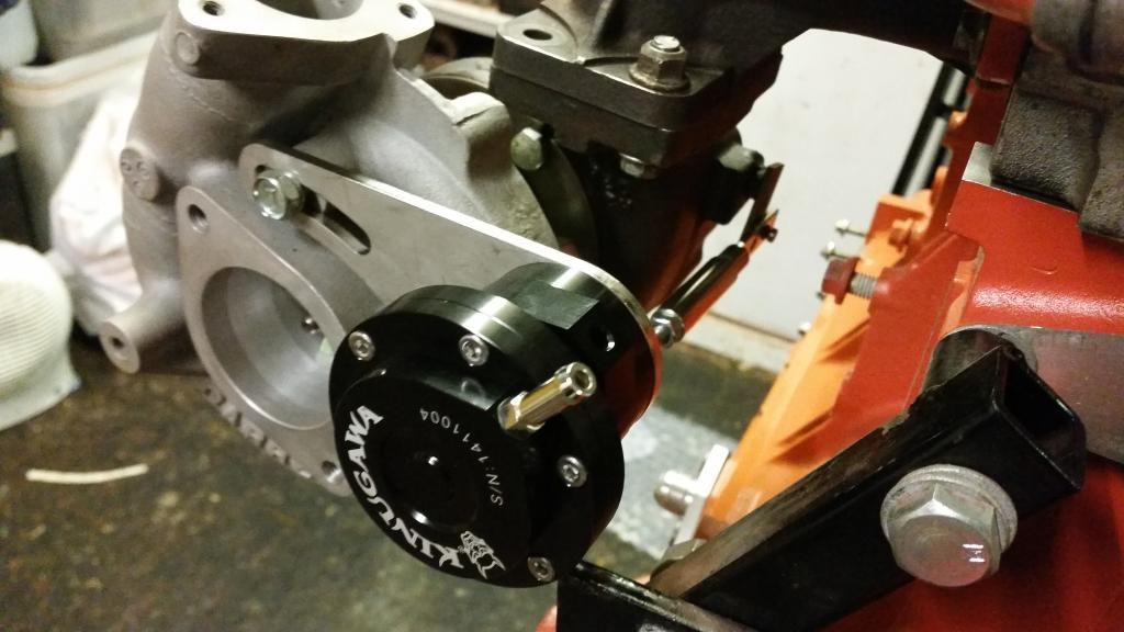
Test fitted Kinugawa Actuator to the turbo - I'm using this because the turbo didn't come with an actuator and this came with a handy adjustable bracket and various combinations of rod. It's from Japan and is a lovely piece of kit which certainly looks well made. They supplied it fitted with a 0.5 bar (7 psi) spring but I also have a 0.8 bar (11.6psi) spring if I need it. I'll be running an electronic boost controller so will decide later which spring I actually use. I'm very impressed
Cylinder head, that is. The original plan was to keep the Variable Valve Timing to see how it coped with forced induction. The VVC only works on the inlet and varies the duration from 220 degrees to 295 degrees as rpm increases. It does this by slowing the cam down as the lobe opens the valve. It's a clever but fragile system. They are always loud and most VVCs sound a little bit diesel! That said, it works and they are a hoot to drive.
My turbo is probably too restrictive for the big overlap the VVC produces at full duty, but since I can control it with the Emerald ECU I figured I could just keep it at low duration if it caused problems. The intention was to tune it for optimum results. It didn't quite work out and I went in a different direction in the end. More on that later. For now, I'll share what I did anyway.
I had a nightmare finding a good VVC head that hadn't been skimmed to hell and back. Unfortunately a lot of VVC engines have had hgf which led to overheating and a softening of the head. This causes the liners to indent the head so I was looking for one without those telltale sunken areas around the fire rings.
The head I ended up using was from a Caterham. It was basically good and had only ever had a light skim. I dropped it off for a quick porting with TDR motorsport by Brands Hatch who I know through the BRM forum. They opened everything up for improved flow and matched the ports to inlet and exhaust manifolds. You'll see a fair bit of meat was left on the valve guide bosses to help heat dissipation.
Before:
After:
I then turned my attention to the lifters. They weren't too bad but the cam-lobe surfaces had some scuffs so I planished them with various grades of wet and dry.
Cleaning:
Planishing:
All in!
Now to the VVC mechs. I had thought to simply transfer the VVC gear from one cam ladder into the other. Unfortunately they needed synching. An hour of reading later and I had it sussed - whilst daunting, it's actually not that difficult and you just have to be patient and careful not to let the mechanisms fall apart while you're handling them! If that happens you're in a world of pain and there are dozens of parts.
I elected to use the SAIC developed so-called "n-series" head gasket. This was quite literally marketed by x-part as the ultimate fix for k-series head gaskets and is comprised of the SAIC developed gasket, grade 10.9 head bolts (with a slightly revised tightening procedure) and the stiffer oil rail.
Many layers:
Head on!!
The gasket compressed to 2mm with the head torqued down. I re-measured the volume of the combustion chamber post porting and skim and I should now have a static compression ratio of almost exactly 9:1. which is what I wanted.
Also took care of a few other bits
Oil pump modified with radius'd edges for improved flow and fitted. I actually did this to the old one then decided to just replace it with new. So had to do it all again (only better - of course!). Naturally, I painted it orange! Also fitted water pump. I am as-yet undecided on the orange bolts - you'll not see these ones anyway but I have a whole engine bay kit - If they look gash I'll use normal stainless.
Test fitted Kinugawa Actuator to the turbo - I'm using this because the turbo didn't come with an actuator and this came with a handy adjustable bracket and various combinations of rod. It's from Japan and is a lovely piece of kit which certainly looks well made. They supplied it fitted with a 0.5 bar (7 psi) spring but I also have a 0.8 bar (11.6psi) spring if I need it. I'll be running an electronic boost controller so will decide later which spring I actually use. I'm very impressed
Edited by Stuballs on Wednesday 4th October 14:11
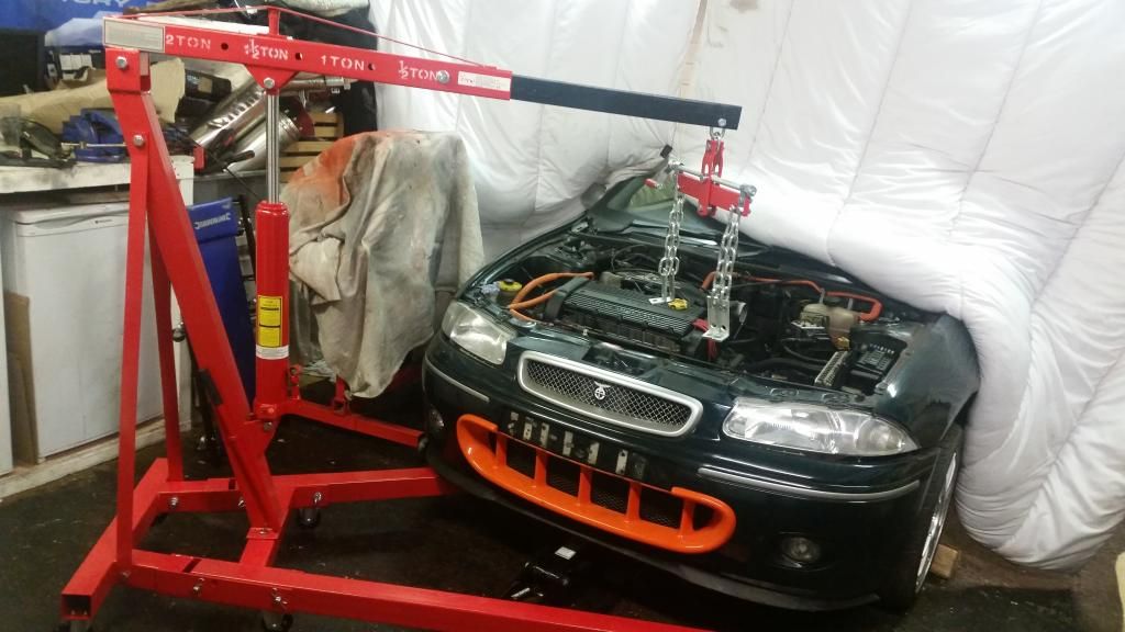
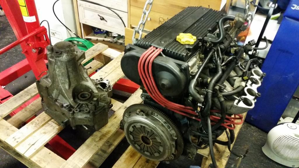
So I'd gone about as far as I could with the engine without needing donor bits from the engine in the BRM. So time to whip out the old leaky lump! Decided just to buy an engine crane rather than hire. No time pressure then and I can just sell it when I'm done with it. For an Ebay cheapy it's a great bit of kit.
Front bumper off
Let the lifting commence!
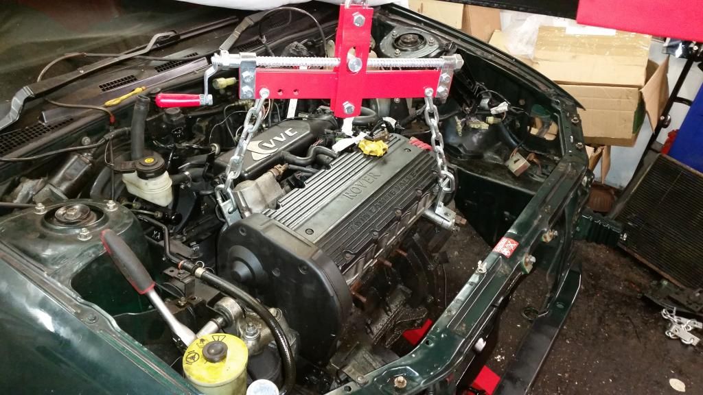
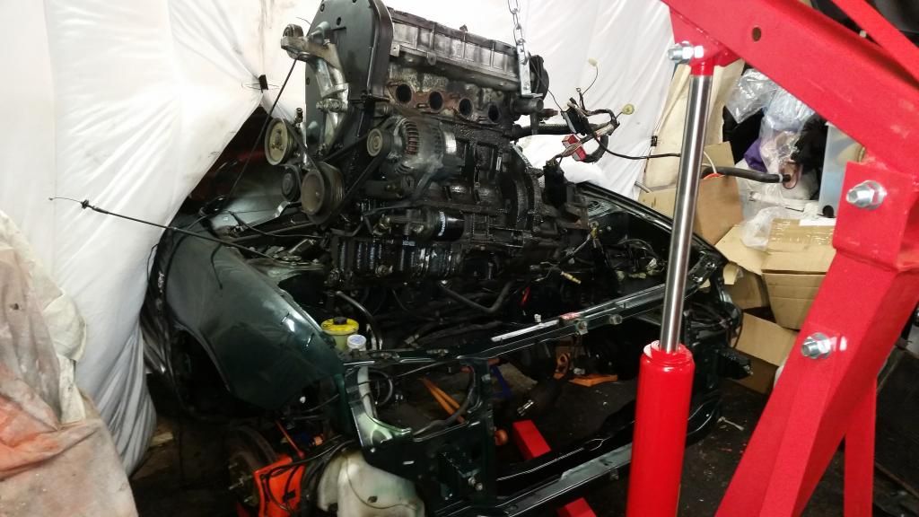
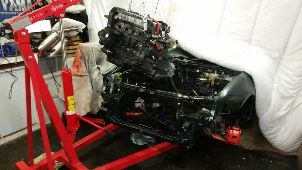
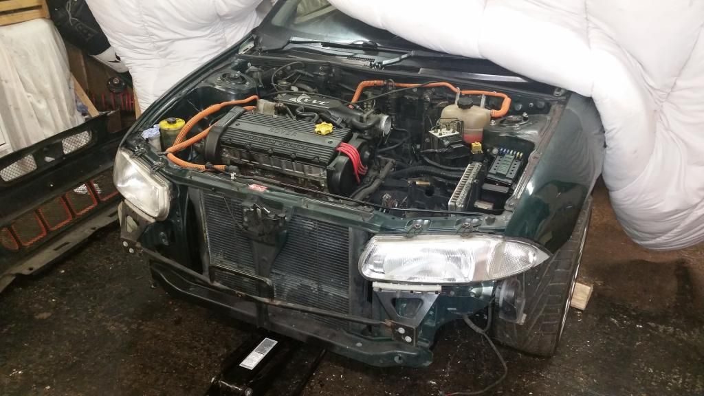
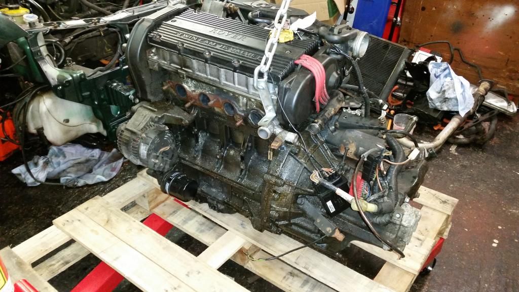
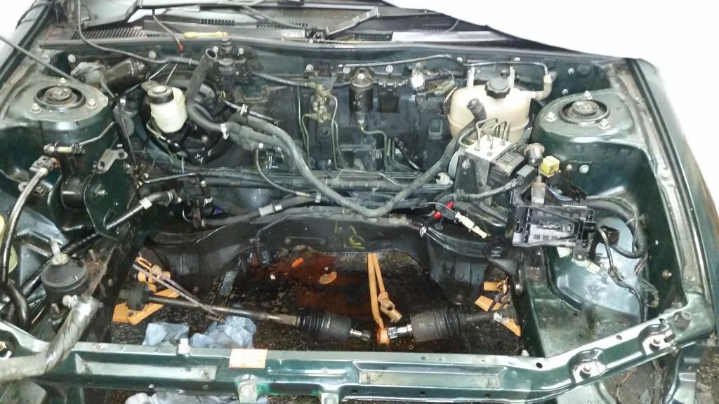
She's free! And my god in such an awful state. Imagine an engine put together with no gaskets and this is the level of oil leak.
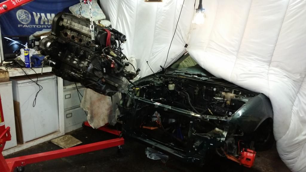
We'll just set this to the side for later...
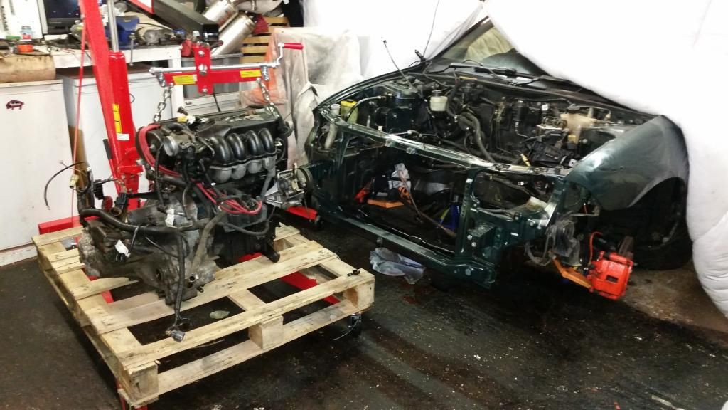
Got the gearbox off and cleaned up a bit as I'll be needing that later...
Engine bay doesn't look too bad in this pic but in the flesh it was very grubby. Sound proofing disintegrating and everything just covered in a film of grease.
Several hours' and a few cans of silicone spray later:
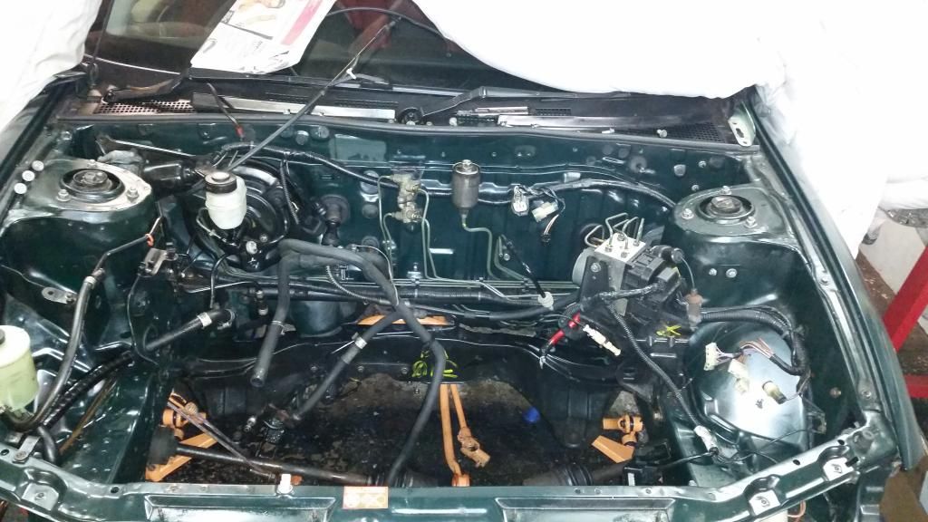
I removed all the brackets to clean them properly and apply a lick of paint. Trying out this orange bolt kit I got. Not sure yet. will see how it looks once all together. Managed to clean the expansion bottle out with plenty of washing powder and a handful of pea shingle shaken like a maniac. Came up as new!
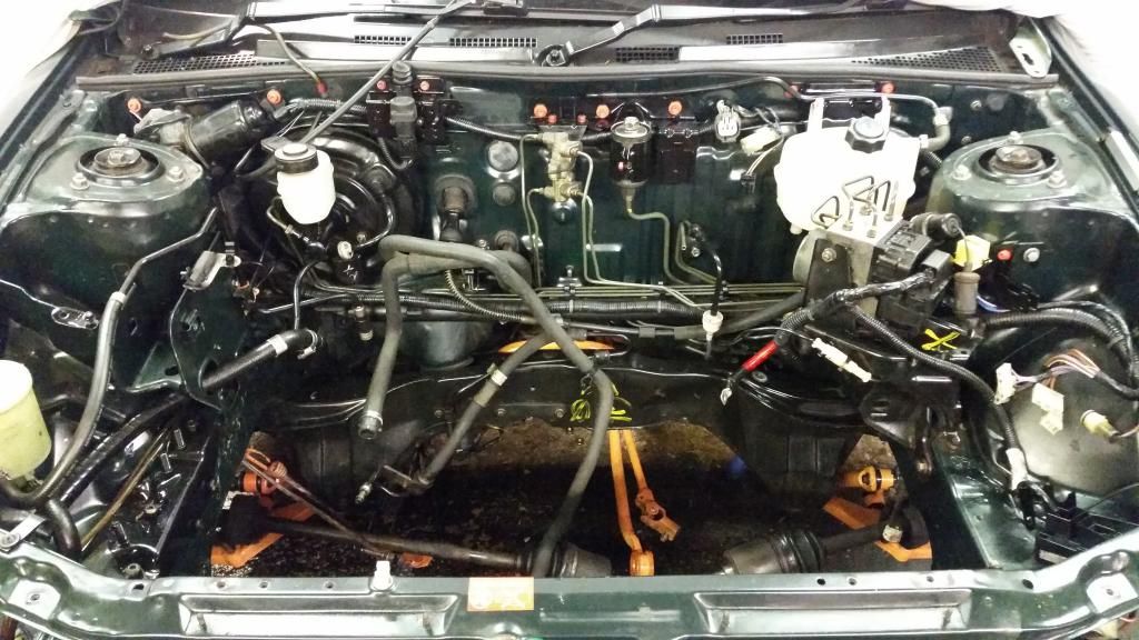
There then followed a long period of prepping, priming and painting various brackets and engine mounts. I've become somewhat obsessed with the black and orange!
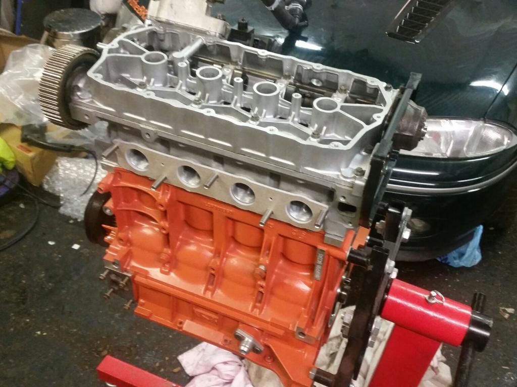
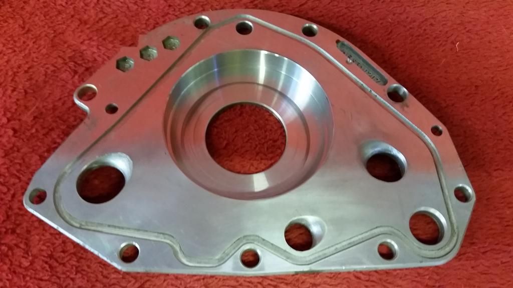
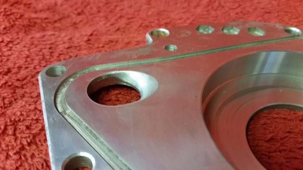
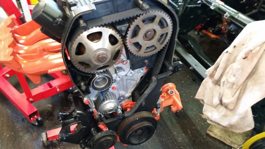
Stripping the old engine down gave me access to bits I need for the new engine, which included the cambelt rear cover. So fitted the cambelt.
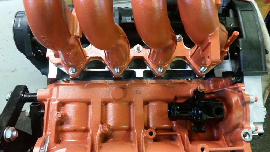
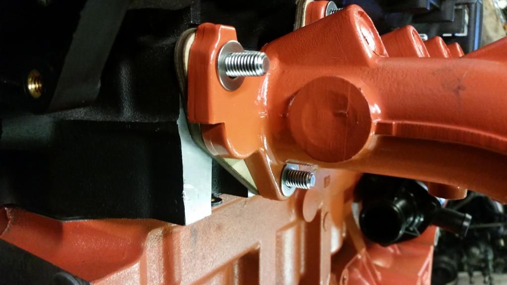
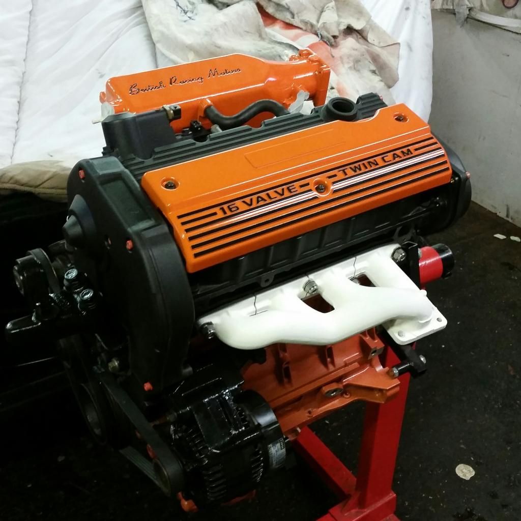
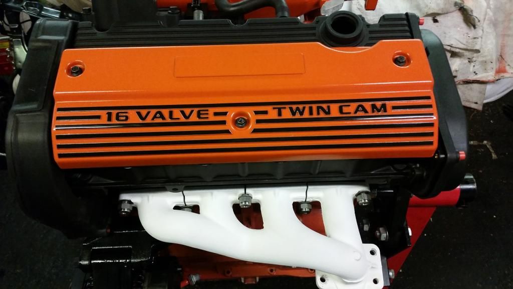
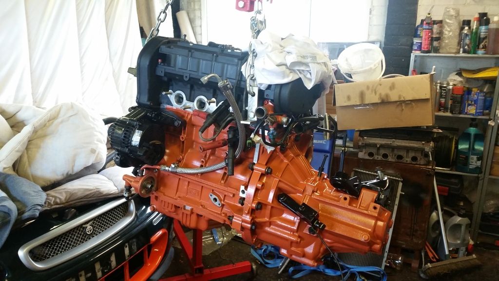
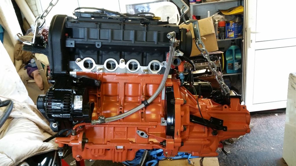
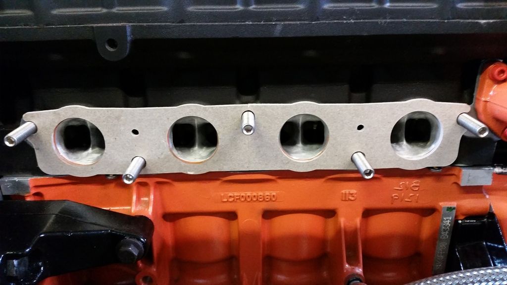
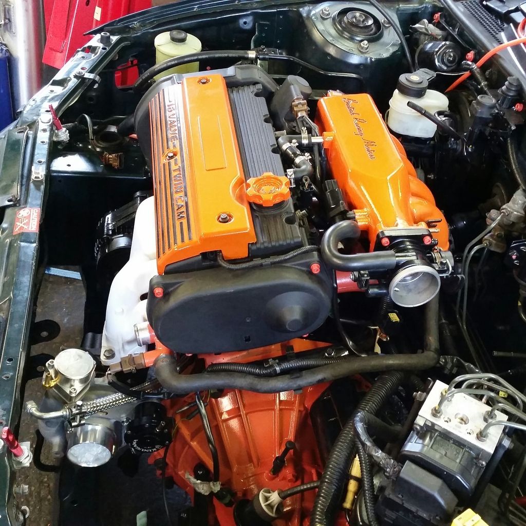
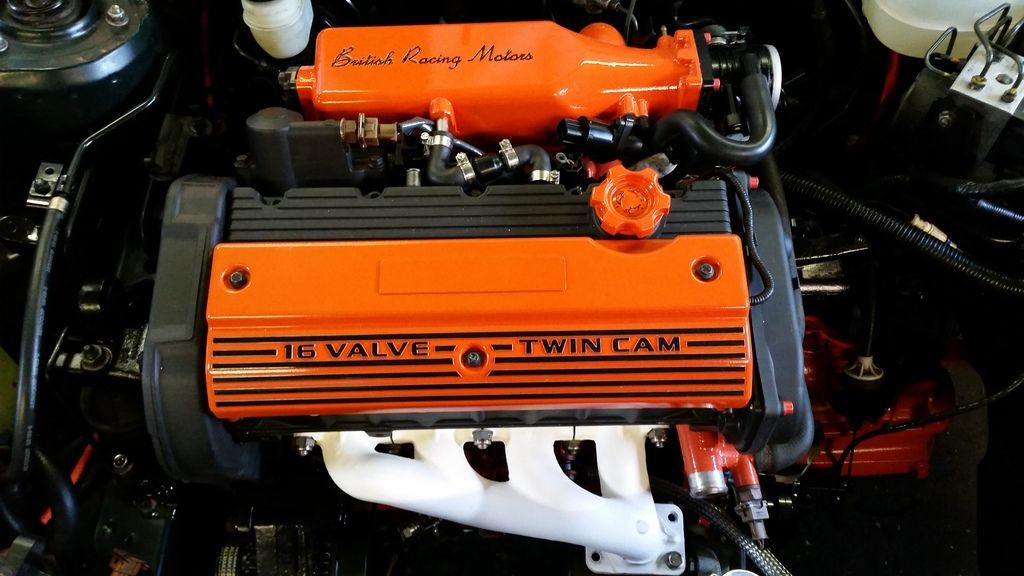
Getting the engine built back up with ancillaries and more orange bolts (still not sure...) and the orange inlet manifold. Note the special Ferriday thermal gasket to keet the temperature of the inlet runners down. this, unfortunately, did not match my matched ports so require very, very careful fettling to match all three up.
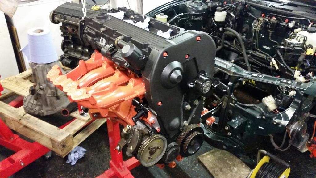
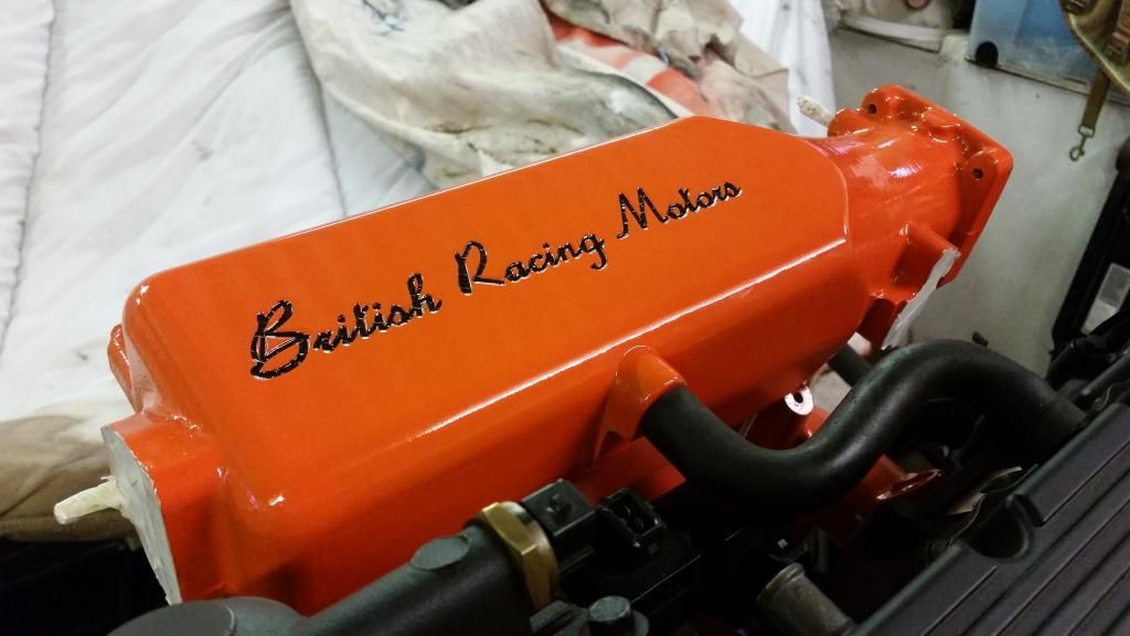
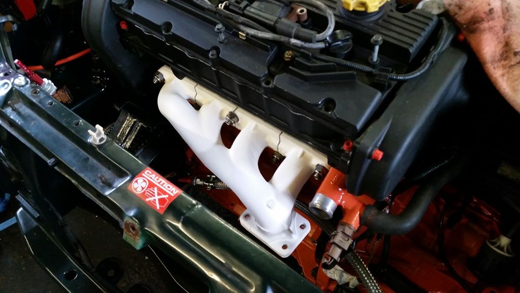
Then I thought I'd better mock up THE bling orange bits just to get an idea of how they'll look. Of course this required getting the ceramic manifold out again for maximum effect. The inlet plenum is a one-off mod a fellow BRM owner had done years ago. Standard just has the embossed "VVC".
Then sorted the engine loom - sticking with the BRM loom so had to sort wiring for the coils which are now plug-top. Love a bit of soldering.
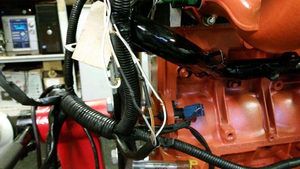
Loom is on and labelled everything!
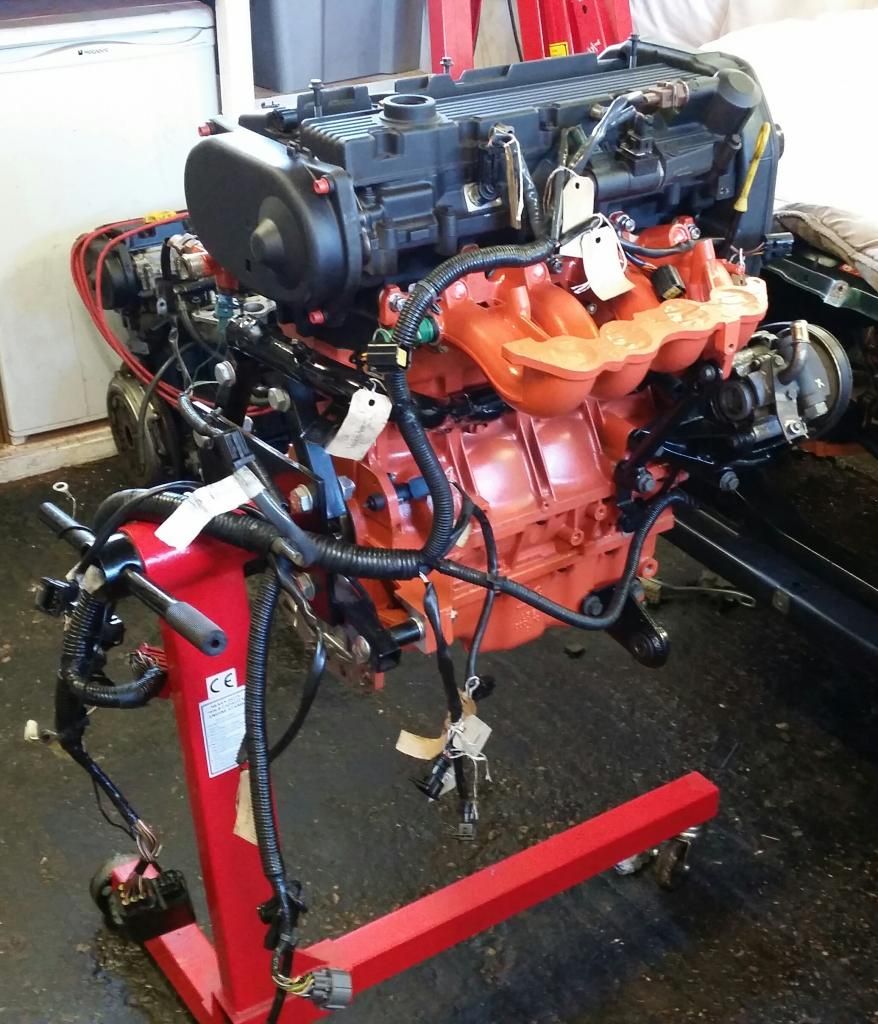
Pretty much ready to go in now...
Front bumper off
Let the lifting commence!
She's free! And my god in such an awful state. Imagine an engine put together with no gaskets and this is the level of oil leak.
We'll just set this to the side for later...
Got the gearbox off and cleaned up a bit as I'll be needing that later...
Engine bay doesn't look too bad in this pic but in the flesh it was very grubby. Sound proofing disintegrating and everything just covered in a film of grease.
Several hours' and a few cans of silicone spray later:
I removed all the brackets to clean them properly and apply a lick of paint. Trying out this orange bolt kit I got. Not sure yet. will see how it looks once all together. Managed to clean the expansion bottle out with plenty of washing powder and a handful of pea shingle shaken like a maniac. Came up as new!
There then followed a long period of prepping, priming and painting various brackets and engine mounts. I've become somewhat obsessed with the black and orange!
Stripping the old engine down gave me access to bits I need for the new engine, which included the cambelt rear cover. So fitted the cambelt.
Getting the engine built back up with ancillaries and more orange bolts (still not sure...) and the orange inlet manifold. Note the special Ferriday thermal gasket to keet the temperature of the inlet runners down. this, unfortunately, did not match my matched ports so require very, very careful fettling to match all three up.
Then I thought I'd better mock up THE bling orange bits just to get an idea of how they'll look. Of course this required getting the ceramic manifold out again for maximum effect. The inlet plenum is a one-off mod a fellow BRM owner had done years ago. Standard just has the embossed "VVC".
Then sorted the engine loom - sticking with the BRM loom so had to sort wiring for the coils which are now plug-top. Love a bit of soldering.
Loom is on and labelled everything!
Pretty much ready to go in now...
Edited by Stuballs on Wednesday 3rd January 13:10

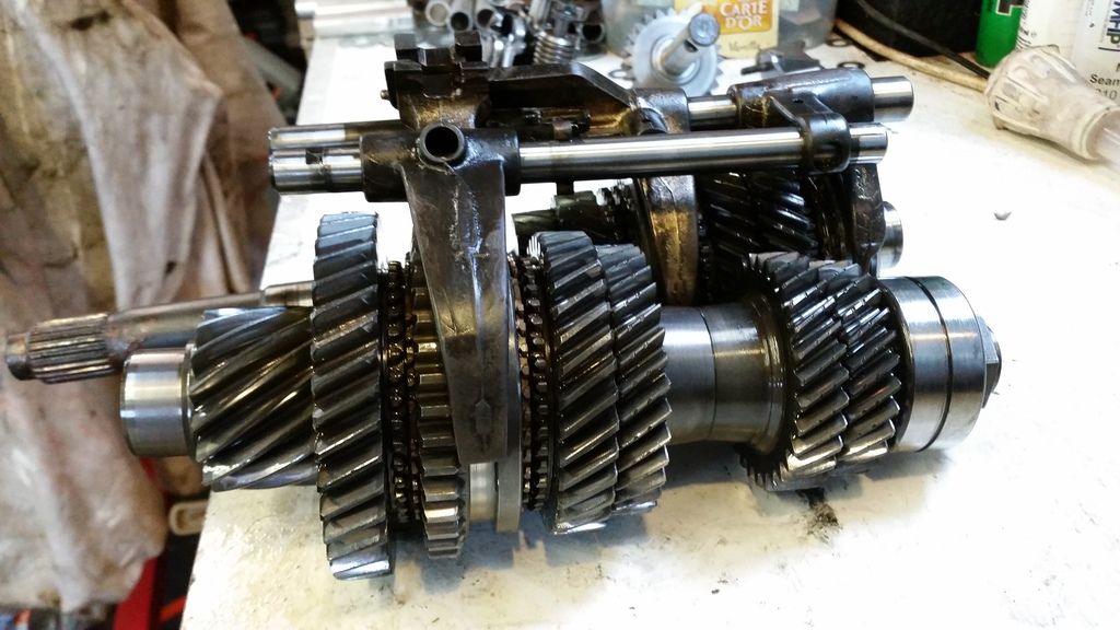
Time to get the engine in, but first to upgrade the gearbox :
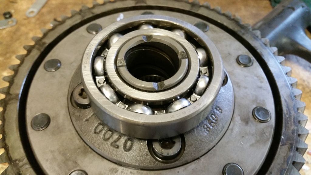
Nothing too fancy - just upgrading the bearings to steel caged items in place of the chocolate versions rover used in the pg-1. I'm using the BRM box that comes with Type B Torsen limited slip diff.
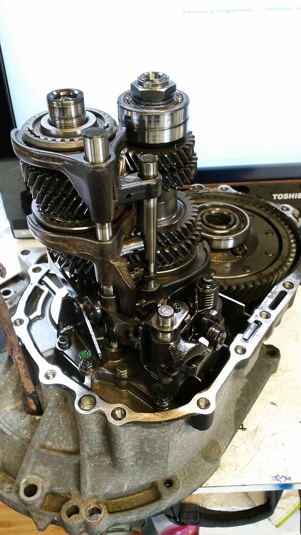
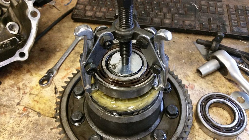
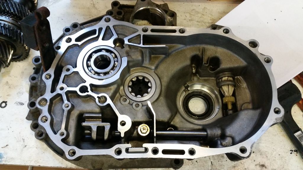
started by stripping the 'box down
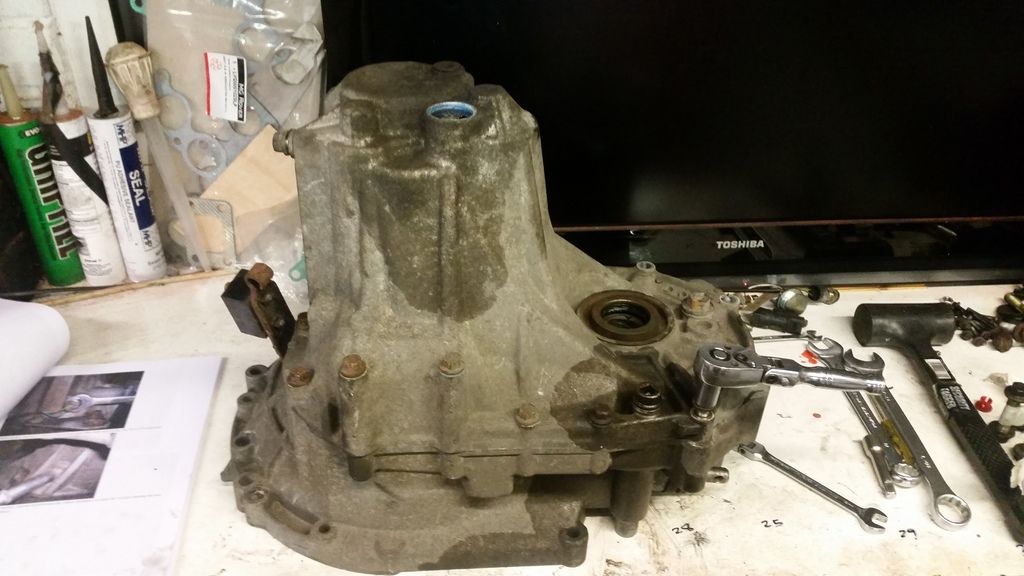
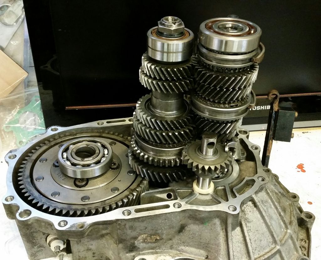
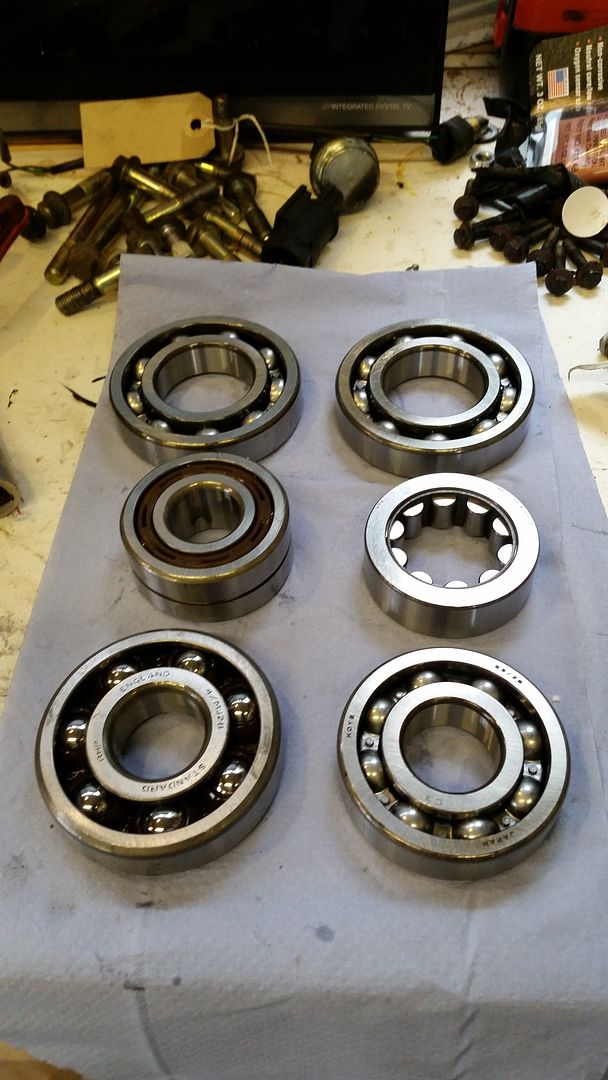
new bearings ready to go:
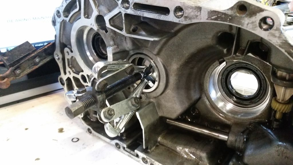
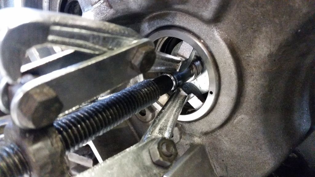
Getting the bearings out is easy with careful use of heat and bearing pullers
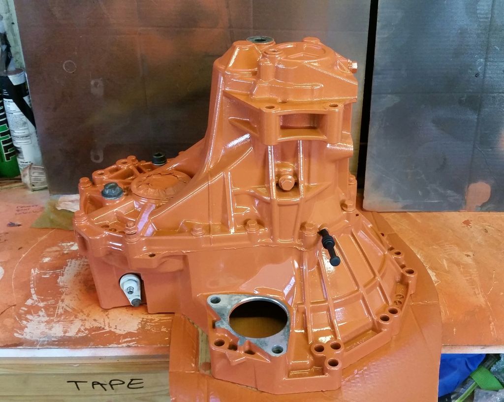
Painted to match the engine
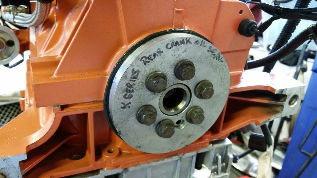
Fitting the rear crank oil seal in using a homemade tool borrowed from a buddy.
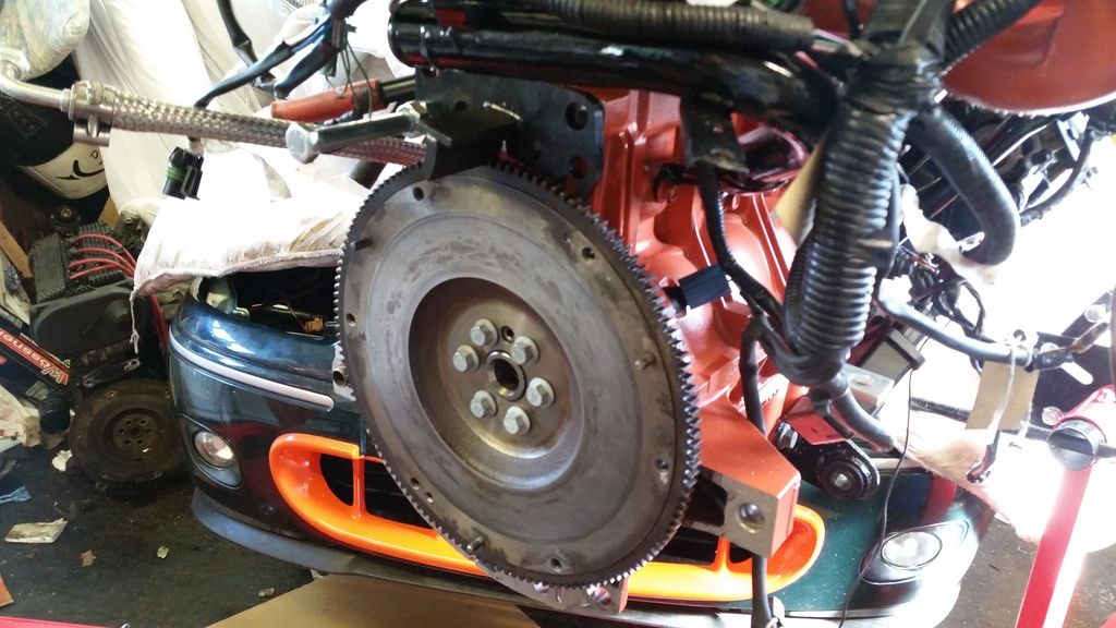
Flywheel on with new bolts of course. This is a Freelander 2 flywheel which allows me to use the slightly larger 220 turbo clutch, but still has k-series fitment. I elected not to go for a lightened crank as everyone else seems to do. I was talked into this by Vibration Free who did my balancing. I slightly regret the decision but this will make for an easier to drive car. Obviously I can always fit a lighter unit later down the road if I feel the need.
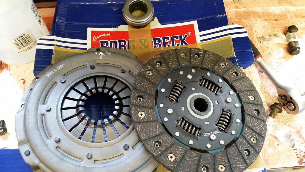
Here's my clutch - Shouldn't be aggressive at all and pedal is nice and easy. Let's see if it can cope with the torque I make. Clutch cover was balanced with the flywheel and everything else that moves in the bottom end.
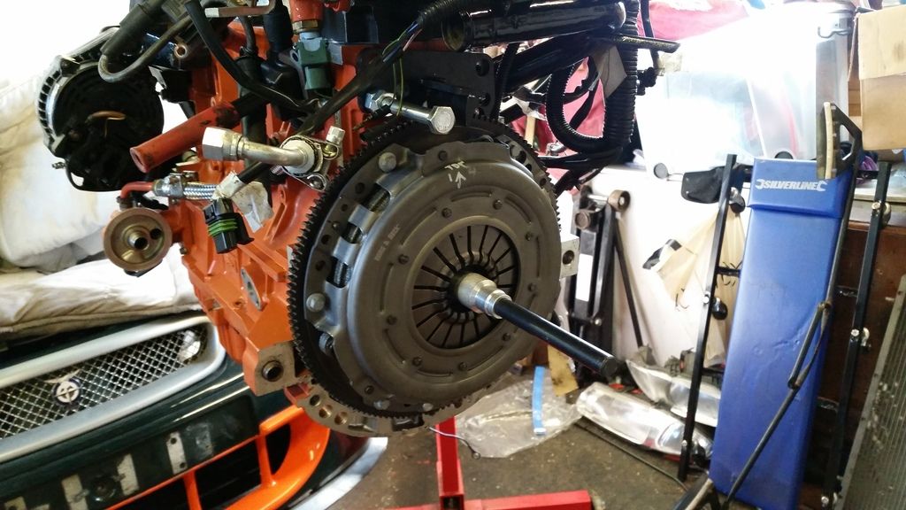
Gearbox on!
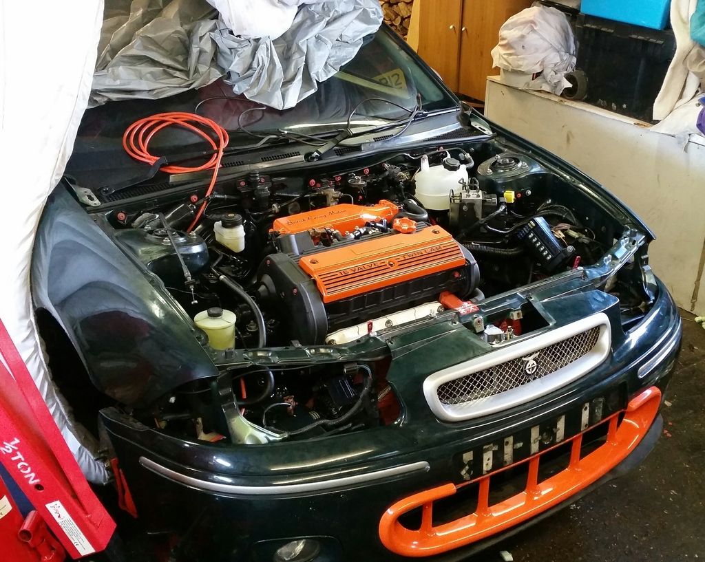
Now the really exciting bit.

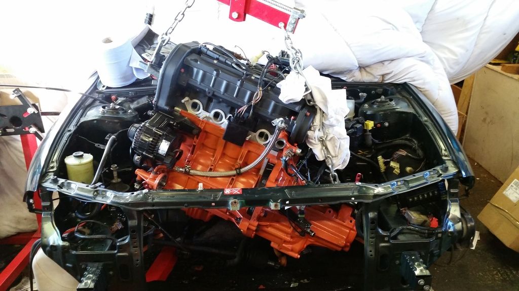
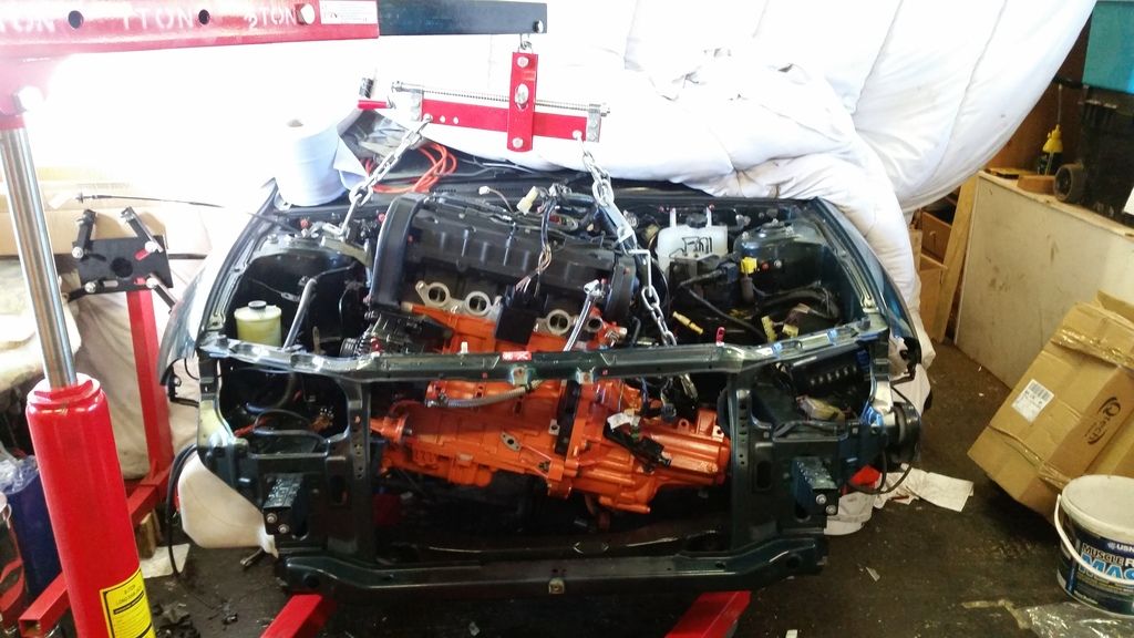
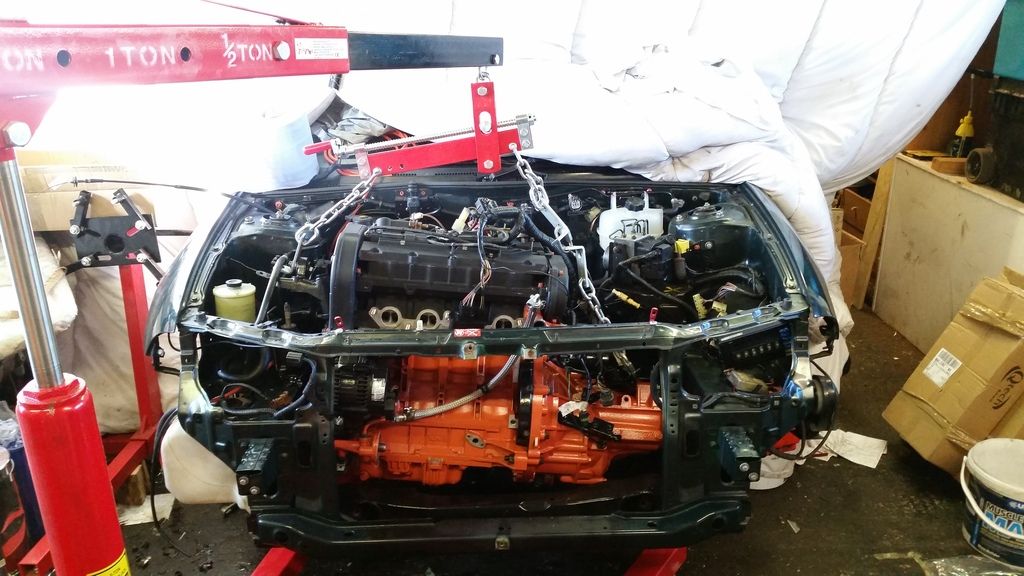
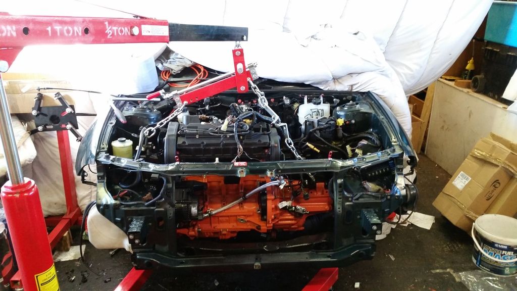
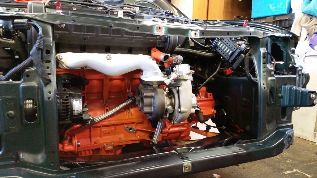
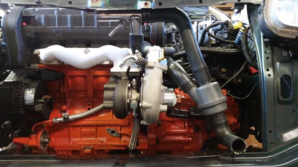
IN!!!!!
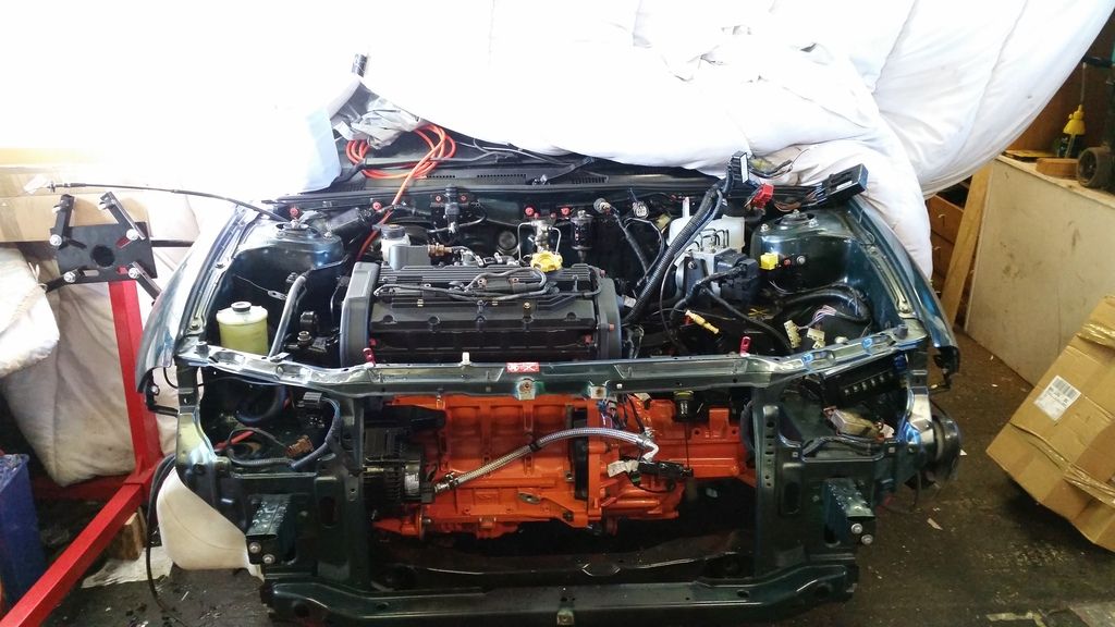
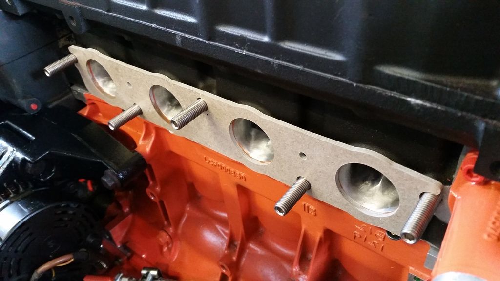
Now to get the manifold on. I'm using a Ferriday thermal gasket that reduces heat transfer back into the head (very good idea for k-series). It needs a bit of help sealing so on goes a bit of high temp gasket. (Look at those ports!)
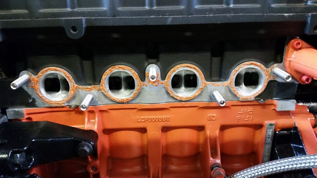
Thermal gasket in place - ports match up quite well luckily!
Zircotec ceramic coated manifold on:
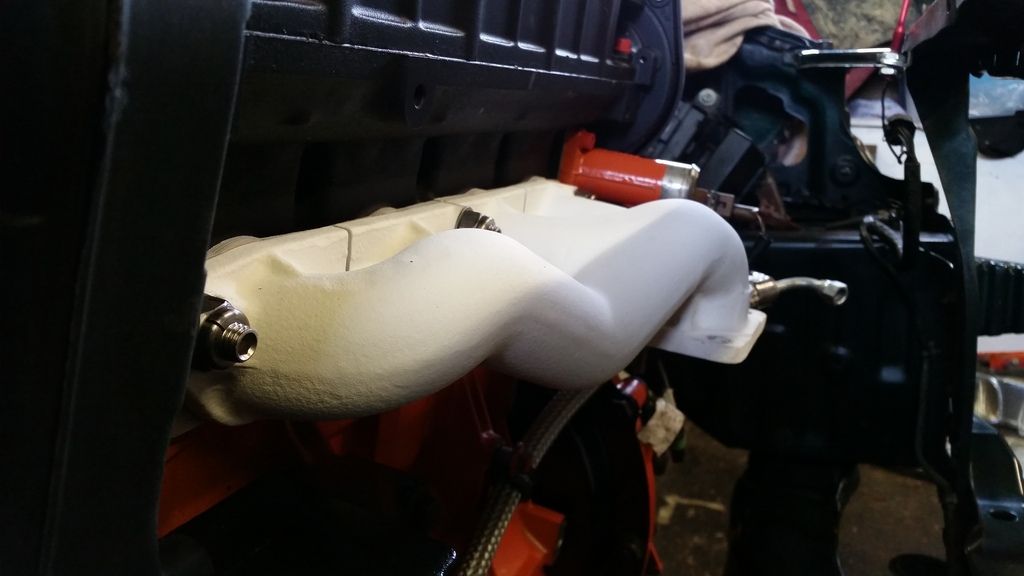
And the turbo (T28r from a 200SX - rebuilt with a billet wheel and fitted with a Kinugawa actuator from Japan).
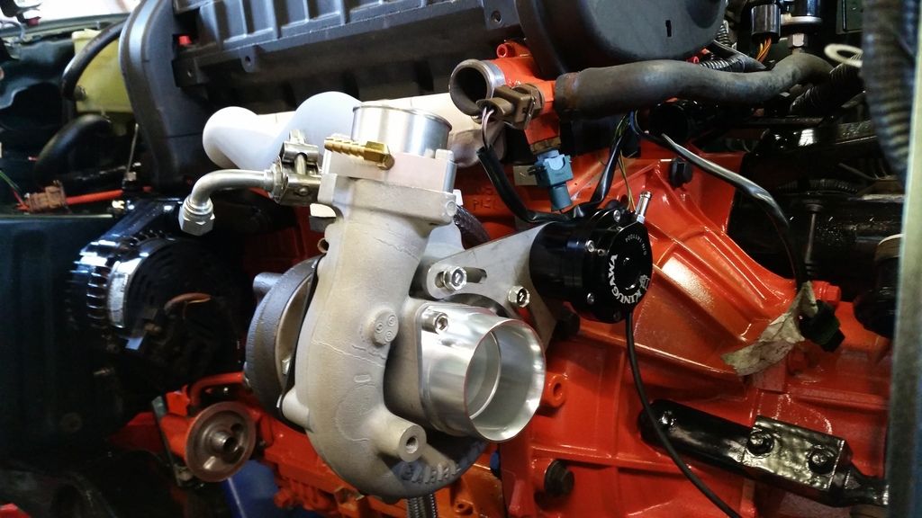
Test fitting a few bits.
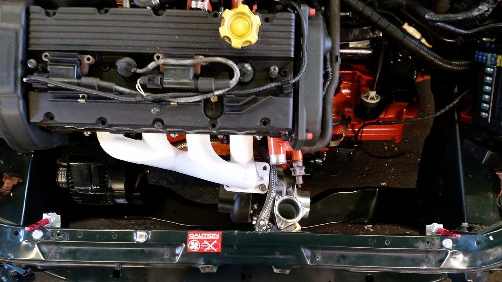
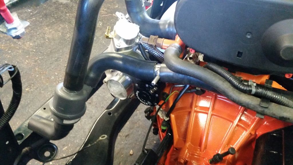
Then fitting the pressure relief thermostat (prt). This replaces the regular thermostat that would normally sit behind the block right at the pump inlet. It reduces thermal shock caused by cold coolant rushing into the hot block when the thermostat opens and it opens add rpm rises, not must tempetature. This is designed for a freelander so had to really chop and swap around the pipes to fit but this should work really well. I'm fairly confident I've got it right! Still have the plumb in the turbo feed and drain. The tee from the pipe going to the pump will feed it cold water and the tee in the top hose will take the hot water away.
Next job is to send her off for a full turbo - back stainless exhaust system...
Nothing too fancy - just upgrading the bearings to steel caged items in place of the chocolate versions rover used in the pg-1. I'm using the BRM box that comes with Type B Torsen limited slip diff.
started by stripping the 'box down


new bearings ready to go:

Getting the bearings out is easy with careful use of heat and bearing pullers


Painted to match the engine

Fitting the rear crank oil seal in using a homemade tool borrowed from a buddy.
Flywheel on with new bolts of course. This is a Freelander 2 flywheel which allows me to use the slightly larger 220 turbo clutch, but still has k-series fitment. I elected not to go for a lightened crank as everyone else seems to do. I was talked into this by Vibration Free who did my balancing. I slightly regret the decision but this will make for an easier to drive car. Obviously I can always fit a lighter unit later down the road if I feel the need.
Here's my clutch - Shouldn't be aggressive at all and pedal is nice and easy. Let's see if it can cope with the torque I make. Clutch cover was balanced with the flywheel and everything else that moves in the bottom end.
Gearbox on!
Now the really exciting bit.
IN!!!!!
Now to get the manifold on. I'm using a Ferriday thermal gasket that reduces heat transfer back into the head (very good idea for k-series). It needs a bit of help sealing so on goes a bit of high temp gasket. (Look at those ports!
)Thermal gasket in place - ports match up quite well luckily!
Zircotec ceramic coated manifold on:
And the turbo (T28r from a 200SX - rebuilt with a billet wheel and fitted with a Kinugawa actuator from Japan).
Test fitting a few bits.
Then fitting the pressure relief thermostat (prt). This replaces the regular thermostat that would normally sit behind the block right at the pump inlet. It reduces thermal shock caused by cold coolant rushing into the hot block when the thermostat opens and it opens add rpm rises, not must tempetature. This is designed for a freelander so had to really chop and swap around the pipes to fit but this should work really well. I'm fairly confident I've got it right! Still have the plumb in the turbo feed and drain. The tee from the pipe going to the pump will feed it cold water and the tee in the top hose will take the hot water away.
Next job is to send her off for a full turbo - back stainless exhaust system...
Edited by Stuballs on Wednesday 3rd January 13:13
Edited by Stuballs on Wednesday 3rd January 13:14
Excellent work! Looks great in its home. It will be a formidable little car when it's sorted. I'm interested to know what you will do with the rad and fan. Looks like it will be very tight!
Out of interest, would you mind me asking how much the manifold cost for the zircotec coating? I've heard it's VERY expensive. I could do with keeping the under bonnet temps of my kit car down. I have them heat wrapped at the moment but have heard that this coating with reduce it further.
Keep up the good work mate
AdamIndy said:
... I'm interested to know what you will do with the rad and fan. Looks like it will be very tight!
...
Out of interest, would you mind me asking how much the manifold cost for the zircotec coating?
Keep up the good work mate
Thanks! ...
Out of interest, would you mind me asking how much the manifold cost for the zircotec coating?
Keep up the good work mate
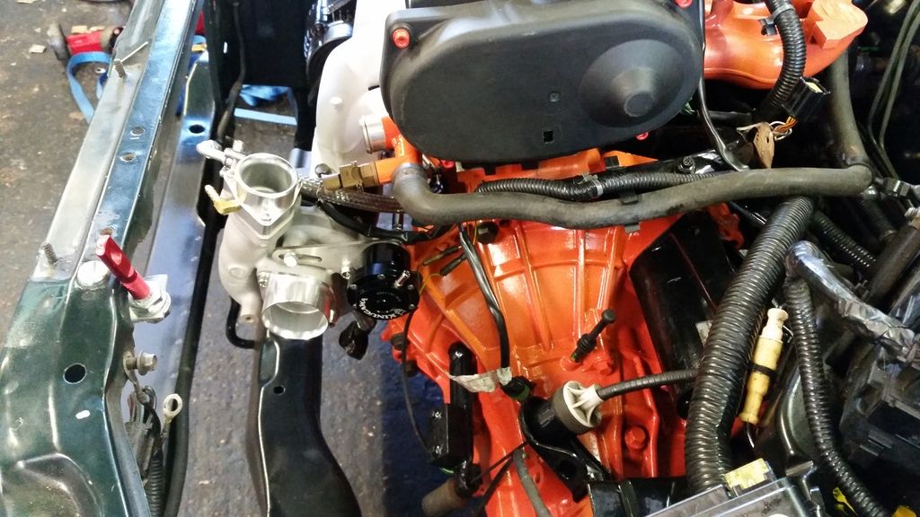
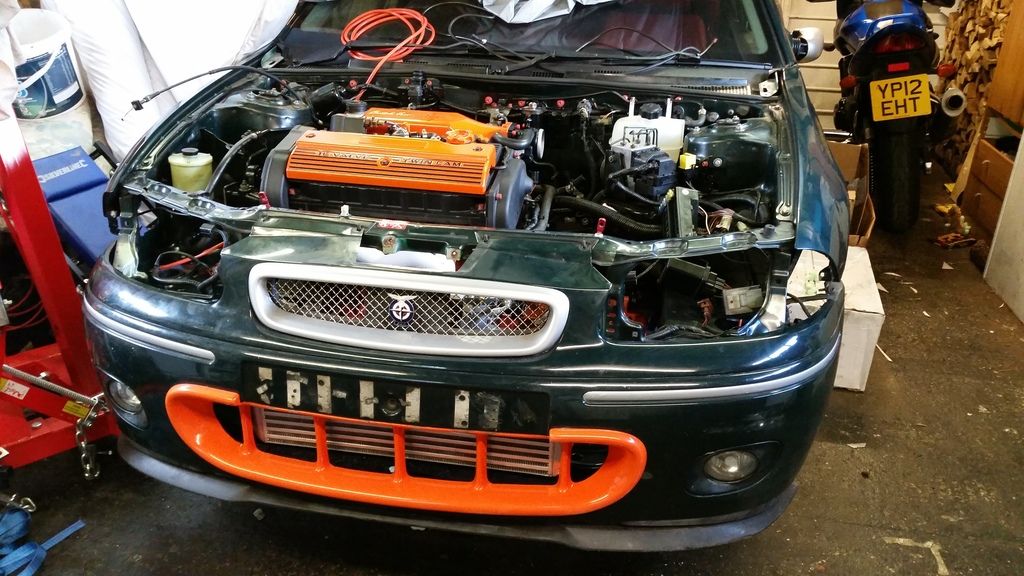
Rad had to be moved forward an couple of inches so I could fit some spal slimline fans on the back and have the intercooler and oil cooler in front of it. I had a custom copper rad made by a friend on rovertech forum. I'll post more on that in a bit but you'll ree I have about 5mm clearance between the fan casing and compressor housing!
Ceramic coating was about £250 I think. It's more on tubular manifolds and there are various options for coatings with different prices. I know it's a lot but heat control will be very important in this build so well worth it.
Stuballs said:
AdamIndy said:
... I'm interested to know what you will do with the rad and fan. Looks like it will be very tight!
...
Out of interest, would you mind me asking how much the manifold cost for the zircotec coating?
Keep up the good work mate
Thanks! ...
Out of interest, would you mind me asking how much the manifold cost for the zircotec coating?
Keep up the good work mate
Rad had to be moved forward an couple of inches so I could fit some spal slimline fans on the back and have the intercooler and oil cooler in front of it. I had a custom copper rad made by a friend on rovertech forum. I'll post more on that in a bit but you'll ree I have about 5mm clearance between the fan casing and compressor housing!
Ceramic coating was about £250 I think. It's more on tubular manifolds and there are various options for coatings with different prices. I know it's a lot but heat control will be very important in this build so well worth it.
That zircotec is expensive isn't it! Perhaps a bit too much for me on a full 4branch. Maybe another layer of heat wrap will do me!

Gassing Station | Readers' Cars | Top of Page | What's New | My Stuff