962 recreation with a GT3 Heart...
Discussion


In the spirit of "Time for Tea", I'm not alone in being British, Mad and a car constructor. These guys are bloody funny and very instructive and completely nuts....
Just watch all the videos, see if you can get all the comedy links (Watch the black board if your a Monty Pye fan)
http://www.badobsessionmotorsport.co.uk/test/index...
Just watch all the videos, see if you can get all the comedy links (Watch the black board if your a Monty Pye fan)
http://www.badobsessionmotorsport.co.uk/test/index...
Pesty said:
I've been thinking this. Last weekend I replaced a security light. took me twenty minutes and I came in for a nap.
today I've done FA despite having plenty I could get on with.
So not only am I in awe of the skills needed to do this I'm just amazed he has the energy.
Its like that film unbreakable. I'm Samual L Jackson to his Bruce willis.
today I've done FA despite having plenty I could get on with.
So not only am I in awe of the skills needed to do this I'm just amazed he has the energy.
Its like that film unbreakable. I'm Samual L Jackson to his Bruce willis.


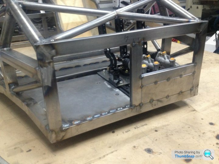
Will post a video of the pedals moving under there own steam once I have the drive shafts sorted.... but for now...
https://www.youtube.com/watch?v=CTFQ9rxbEsI&li...
Well just for giggles I found the weight of a std GT3RS that the engine came from is 3070lbs, should be able to knock at least 1000lbs of that, wounder what that's going to do for the Acceleration times.....
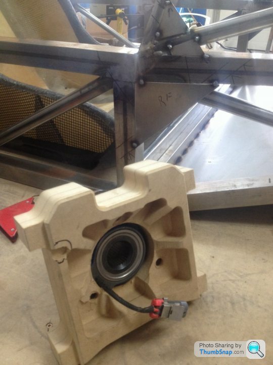
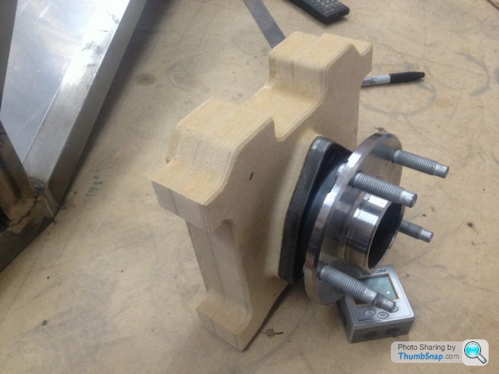
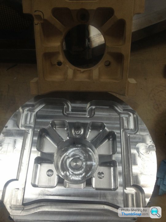
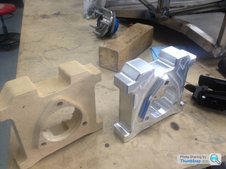
Anyway, back to work, well actually its time for bed here but we did manage to get the first side of the CNC machining tested on the new design front upright.. MDF is lovely stuff and when glued together is great for prototyping new CNC parts before attacking your $250 of 6061 billet.... and as the keen eyed among you will spot I made a little error (ringed in black pen) but that is now corrected in the program.
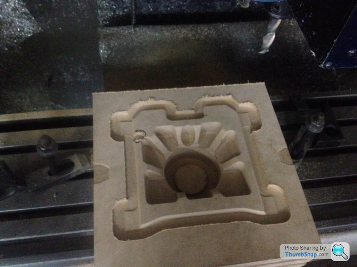
Anyway, back to work, well actually its time for bed here but we did manage to get the first side of the CNC machining tested on the new design front upright.. MDF is lovely stuff and when glued together is great for prototyping new CNC parts before attacking your $250 of 6061 billet.... and as the keen eyed among you will spot I made a little error (ringed in black pen) but that is now corrected in the program.

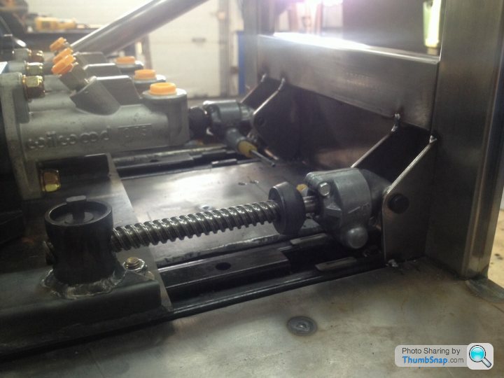
Yes it's possible to overcome the acme stile thread if you push hard enough, but then you have to take into account the screws are also worm gear driven from the motor. Now the force needed has been increased by a factor of 10 again. Think of a block and tackle no brake but can hold 2 tons no problem . I did wonder if any of these electric seats frames actually had a catch lock on them like a normal manual frame, but it seemed none of them did, I checked my GMC Truck it has no catch, and the seat belt is attached to the seat at both ends so must be able to take say a bad accident G load with out moving.
The F1 guys talk about putting 100-150 kgs of force into the brake pedal, so lets say that's 75kgs per screw in compression that's an easy load to take to be honest. But yes I did think about it before I started and did a little research, valid question though bud Keep um coming, I'll take good ideas from anywhere, I'm not proud if it builds a better car.
The F1 guys talk about putting 100-150 kgs of force into the brake pedal, so lets say that's 75kgs per screw in compression that's an easy load to take to be honest. But yes I did think about it before I started and did a little research, valid question though bud
Keep um coming, I'll take good ideas from anywhere, I'm not proud if it builds a better car.AlmostUseful said:
Awesome build.
I have so many ideas of things I'd like to build, it's just the time, space, money and most lacking of all, ability that's holding me back.
So in the mean time I'll stick with pissing around with mountain bikes and use threads like this to keep me happy.
Not much between you and the dream then, just Money.....(apparently it buys anything)I have so many ideas of things I'd like to build, it's just the time, space, money and most lacking of all, ability that's holding me back.
So in the mean time I'll stick with pissing around with mountain bikes and use threads like this to keep me happy.

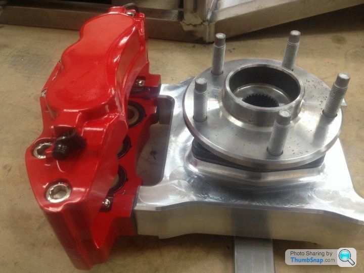
Test fit of caliper rotor before starting to machine the billet...
https://www.youtube.com/watch?v=isKYl-N8FZk
and got some drive shafts made for the pedal box, so here it is moving under 12V power ....
https://www.youtube.com/watch?v=OKx2mv30bus
https://www.youtube.com/watch?v=isKYl-N8FZk
and got some drive shafts made for the pedal box, so here it is moving under 12V power ....
https://www.youtube.com/watch?v=OKx2mv30bus
Steve_D said:
Depends which side of the pond you are no.
Steve
Christ don't complicate things bud, I'm losing it as it is.....Steve
Crap few days, Imprezza blow a rad last week ordered another on Ebay not here yet, but I have the good old faithful truck.... Or so I thought, fuel pump went in town today, so $200 to tow it back then GM wanted $400 for a pump unit (Also includes the sender and filter), but the same unit is $100 on Ebay delivered to my door in a weeks time.....
So now using the wife's car for work this week, luckily shes off work.
Broke my roughing cutter for the CNC Friday 6PM, after all the shops where shut, not forgetting Thursday I spent most of it in bed sick ... I'm going to crawl into a hole now and forget these 4 days off.....

The front I know whats happening as far as the suspension design is going, but the rear needed some more thought. Was going to use that old Porsche gearbox casing to space the engine forward away from the new gearbox, but I didn't really like the way it looked or the load paths the suspension/chassis would put into it.
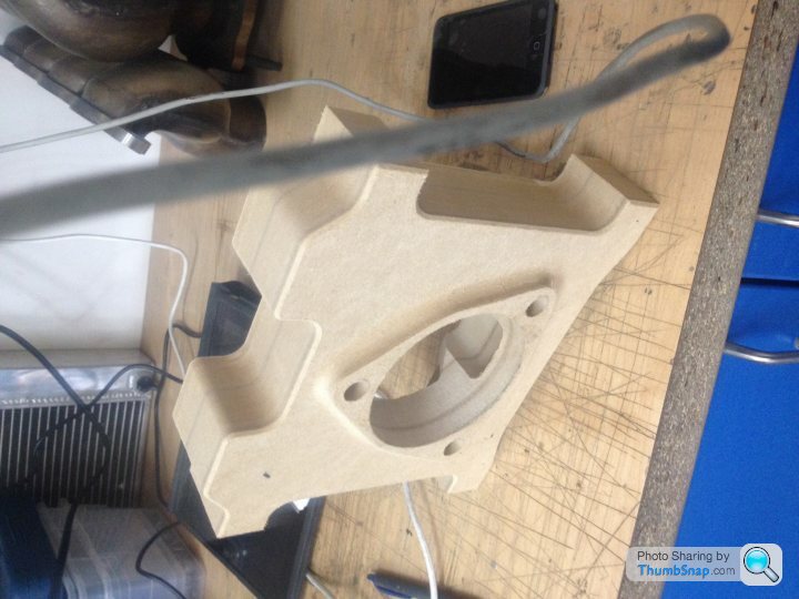
So I've had a few hours head scratching and I think I've come up with a much better solution. Making my own bellhousing and spacer unit, allows me to put the engine and gearbox in exactly the position I want them, with the least compromise so that's whats happening.
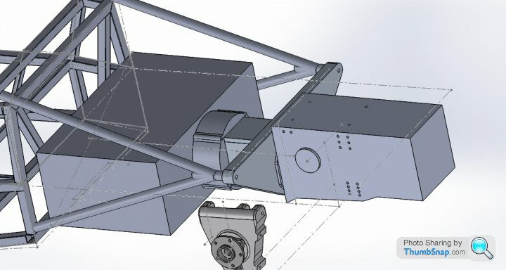
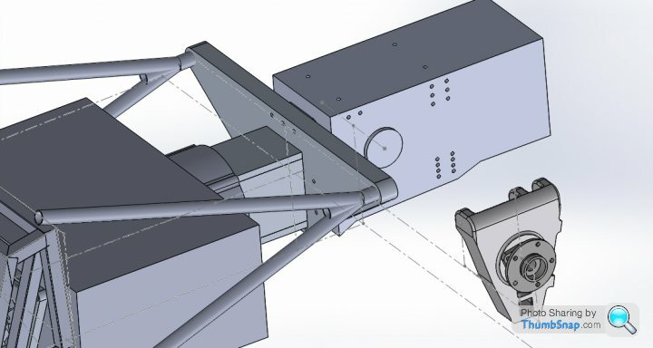
The big rectangular box is the engine, crude yes but its all I need to do the Cad work.
The Triangular plate that connects the chassis to the gearbox was always going to be there but the new parts are between the engine and that plate. Yes basic but I'm just developing the idea for now.
So I've had a few hours head scratching and I think I've come up with a much better solution. Making my own bellhousing and spacer unit, allows me to put the engine and gearbox in exactly the position I want them, with the least compromise so that's whats happening.
The big rectangular box is the engine, crude yes but its all I need to do the Cad work.
The Triangular plate that connects the chassis to the gearbox was always going to be there but the new parts are between the engine and that plate. Yes basic but I'm just developing the idea for now.
Edited by GTRCLIVE on Tuesday 26th August 23:40
There will be 3 tubes per side the last one mounts higher into the cage and is more of a diagonal, and I intend to brace that one with a few X frames. The originals didn't brace it but If i can I will, as it all helps. The engine will take a vertical plain load thought the block, but hopfully not to much twisting load.. 
I did think that on the uprights I made for my car, but is was more of a how do I make these cheaper if I had them cast in batches of say 10 at a time would it bring the price down. For the machining time from a solid billet, and the cost of the billet itself 1 casting then cleanup on the mill could half my costs....
Didn't think of it for the bell-housing though.....uummmm good idea I'll mull that one over Cheers
Didn't think of it for the bell-housing though.....uummmm good idea I'll mull that one over Cheers

Ok the wheel of choice is going to be the CCW's SP20. There a light weight single piece forged wheel, perfect for a road driven car in a Country that does suffer from pot holes due to our cold winters.
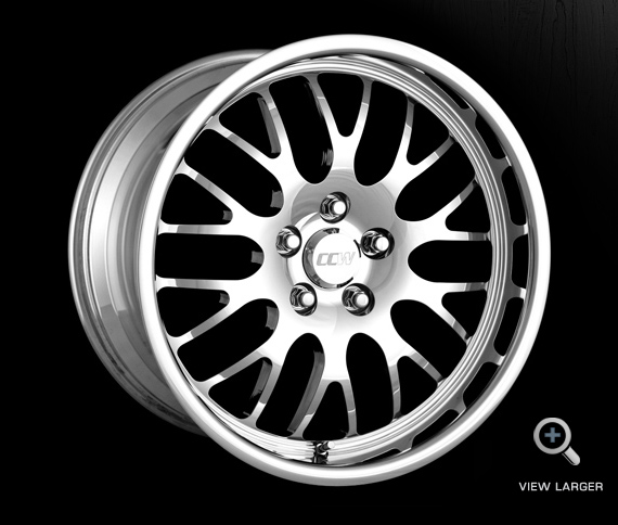
18x11" front 19x13" rears, but with a nice 3" polished lip on both of them more like the 80's race cars had. I didn't go with the Corvette offsets like I used on my project because you just wouldn't get that nice lip to the rim. The large 11" wide front combined with the added height of the wider tire 295/35/18 means I can run less ET offset and still get a Low scrub radius probably in the 30-40mm range. Also the originals had very tall tires anyway. Rears are Enzo tires 345/35/19 for the road, which if a track setup is needed we can swap out for 30% profile R888 or even Hoosier's it will lower the back of the car down 17mm, but I've raised it 20mm over the front giving it a small rake for road driving.
Basically it will have 75mm to 95mm ground clearance for the road (with added Hydraulic lift for speed bumps)
then bolt on your slicks at the race track, and with a small tweak of the spring platforms your down to 60mm front and rear, the ground effects will work better then.
Gassing Station | Porsche General | Top of Page | What's New | My Stuff