Fixing the common "my door wont open" problem (pic heavy)
Discussion


I had a number of problems with my door and windows controls back when I owned my first Cerbera and spent a long time investigating and fixing faults. When people come on here now and post a problem (my door won't open form the outside, my window wont drop, etc.) I always answer "Go buy a multi-meter and get in your boot before you start taking things apart". You can pretty much diagnose the fault from the boot with a multi-meter and either confirm or eliminate a door/window control unit issue.
Well it's time to take my own advice. After parking my car up on Saturday following my disappointing MOT experience I needed to move it around on my drive last night. I pressed the drivers door open button and - nothing. The door would not open from the outside. The inside button was fine so I decided I would produce a short guide on how to diagnose and fix these sorts or problems. Although this is specific to the outer door open switch you can apply the same process to any of the sensors/switches related to door/window functions.
I suspected I may have a switch problem over a control unit problem as the button sometime required two or three hard presses to work previously but it always did work. Now it didn't so it was time to fix the problem properly.
Step 1 - Work out if the door control unit is faulty.
Open the boot and locate your door control unit (on top of the fuel tank, on the right). You can leave all connectors attached if you have a multi-meter with small probes. You are interested in the large/long connector and a description of each wire can be found on one of my previous posts here ( http://www.timmason.com/doorecu1.jpg). Put the positive probe onto the 12v positive supply and then the negative probe onto the sensor/switch you are interested in testing. In my case it is the drives door outer switch A7 which is the last orange wire on the first row. You can see the test setup here:
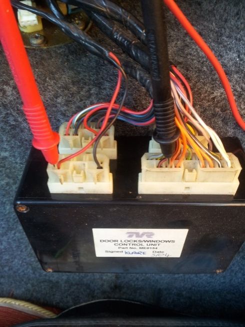
Now it should be reading 0v (or close to 0, say 1.1v or a low reading as some do have a small constant voltage). When the button is pressed it should read 12v. It is helpful to have a helper for this if you are in the boot. Mine didn't change when the button was pressed and to confirm my test was valid I moved the negative probe right one pin onto the next orange wire which is A6 the passenger outer door switch. This had a small voltage and when pressed went to 12v.
Now I knew the fault was with the switch or somewhere between the control unit and the switch but the control unit itself is most probably fine.
Step 2 - Take off the door card.
The door cards are held on by two allen bolts at the front:
Three underneath and three along the rear of the door. Leave the top rear bolt to last to avoid the door card coming away from the door too early and potentially damaging the fiberglass.
TIP: The top bolt on the rear of the door as shown in the photo above is longer than the other two below and must go back into the same location.
As you are undoing the last bolt you will need to support the door card as once it comes away you must unplug this multiplug to remove the card:
Step 3 - Figure out if you have a bad switch or a faulty connection.
With the door card out the way you will see a whole bunch of wires and chances are you are not the first person in here so look out for altered wiring and wire colours. To give yourself a little but more room take out the small door ecu and move it out your way. The try to access the wiring you are left with:
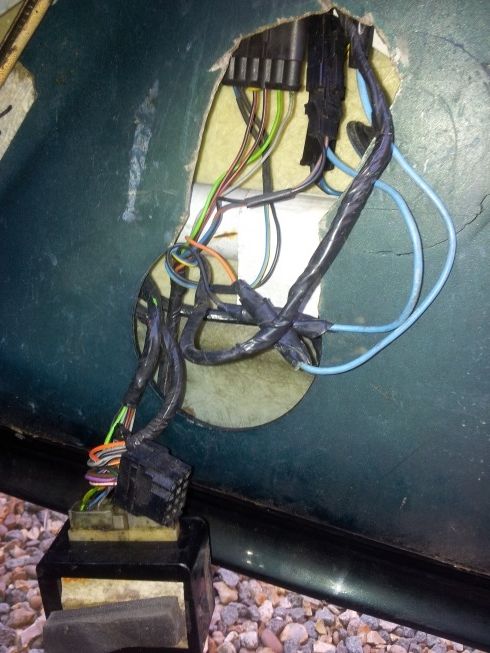
TIP: While you are working on the door now is a good time to check your drain holes are all clear along the bottom of the door (or your door will slowly fill with water and you will be in a world of electrical issues) and fix any rattles. My drives door would rattle when shut and also had a small but not constant rattle when driving. Both these problems are now solved. The rattle when shutting was the small ecu had lost its foam pads that keep it snug and tight in side the door and was rattling around (just glue/tape these back on). The small rattle when driving was down to a bolt and two nuts inside the door which I fished out using a magnet. Obviously they had been dropped inside at some point and somebody couldn't be arsed to fish them out.
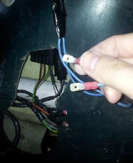
My problem was the outer drivers switch and I know this is an orange wire. You can see the orange wire in the pic above that is connected to a much wider blue wire. The black wire next to it is the other wire to the switch. As is usually the case I am not the first person here and somebody has replaced the outer switch in the past.
I unwrapped the tape to find a couple of spade connectors. Next you need to use your multimeter set to continuity testing to find out if the switch is faulty or if a connection/wire is broken. Remember to unplug the connectors before testing the switch, although if you don't all that will happen is when you test the connectors/wires the door solenoid will fire and that might be a good test in itself to confirm the fault is above that point in the wiring and not below.
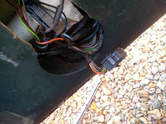
So, connectors unplugged I noticed I had the same arrangement further up the wiring where the blue patched in wires led to. I unplugged those too and pulled the switch wires through the top access hole to I could test them:
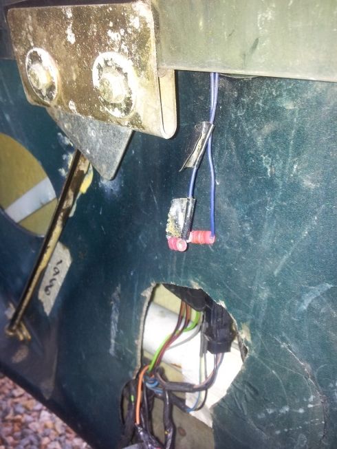
With the probes in place and the switch pressed - nothing still. So not I knew either the switch had broken or another wiring fault further up was the fault.
Step 4 - Removing the outer switch.
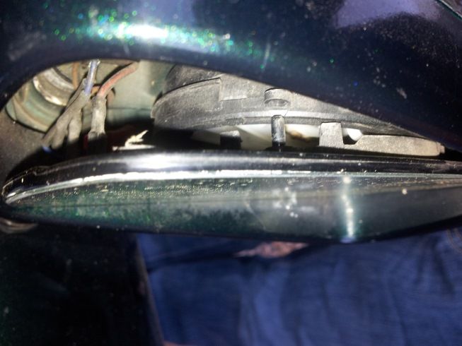
The way you can remove the outer switch is to first carefully remove the mirror glass. The mirror glass is help in place in four corners. You need to gently pry away one corner (I started with inner top) and then using a very small flat headed screwdriver you can lift the remaining tabs and pull the mirror glass out. You will also need to disconnect the heated mirror connections to fully remove the glass:
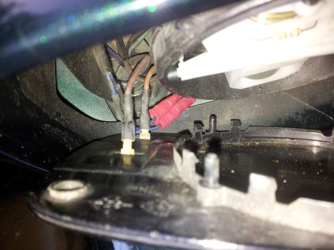
I noticed under the heater mirror connections there was two more connections that go to the door switch. You can see them here with the red crimped connectors:
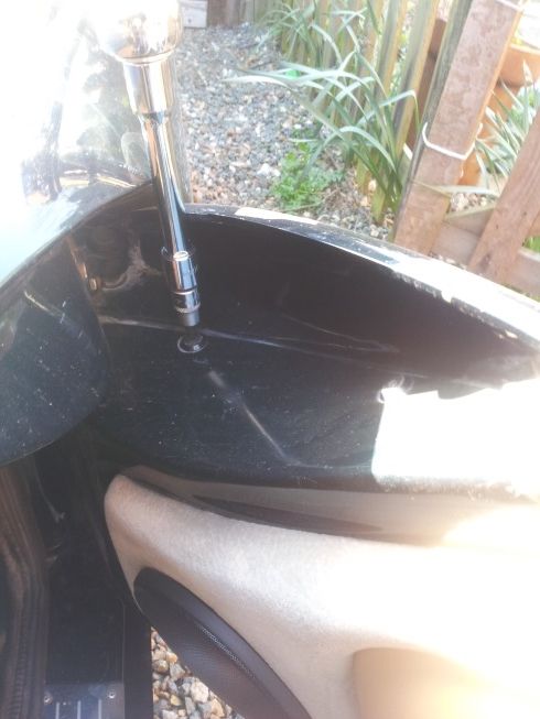
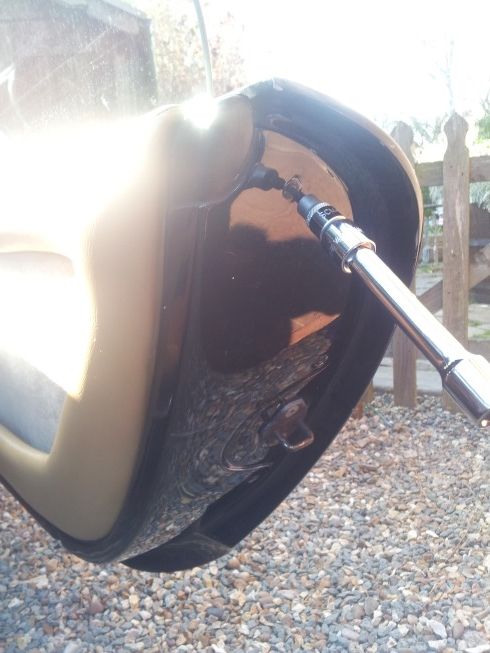
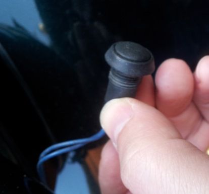
Those connectors were too small for me to test so I thought before I have to cut them out I would see if I could test the switch itself. To remove the switch you need to unscrew it from the brass nut on the inside of the mirror housing:
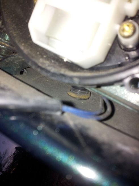
The brass nut will not be tight and you can hold it in place with a flay screwdriver and (with the rubber waterproof cover removed) unscrew the switch from the outside:
It turns out you can't test the switch as the wires are molded into the housing and there is no exposed elements to test. I proceeded to open up those red connectors inside the mirror housing and tested the switch from the ends of the wires.
The switch worked perfectly! So now I know it is a bad connection and I do not have a faulty switch.
Some people say you have to remove the mirror motor and housing to put the switch back in but I found it very easy to just hold the brass nut in place with a large flat screw driver and screw the outer switch in just enough to catch the thread. Then just turn the brass nut with the screwdriver until it is nice and tight - no need to remove the motor housing at all.
Step 5 - Fixing bad connections.
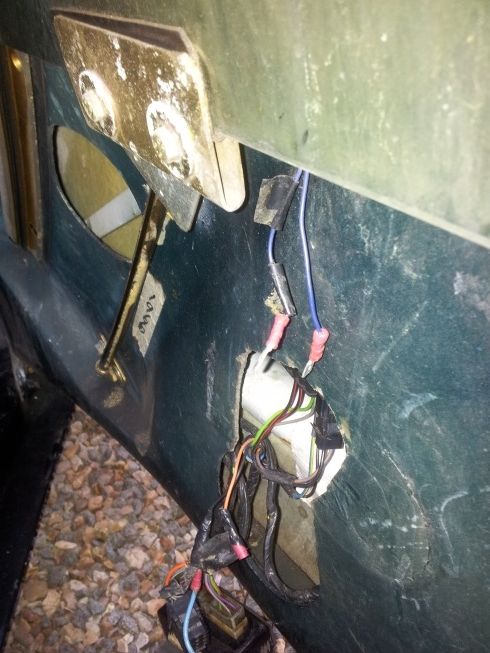
What I knew so far is that the switch works. The switch is connected with two inline connectors inside the mirror housing which leads to two spade connectors inside the door. The two spade connectors inside the door have about 8 inches of thicker wire patched in to reach the bottom set of spade connectors. Here are the various bits of wire and connections in my setup:
A) Switch -> B) inline mirror connector -> C) Door wire spade connector -> D) Patch wire spade connector -> E) Door wire loom -> F) Boot ECU
At the switch side of connection A->B I have continuity but at the first connector side B->C I don't. Easy fix then - I replaced the inline connectors in the door mirror and rested the spade connections at point C:
Still nothing!!
OK, perhaps the spade connectors are at fault - I cut them off and put on new ones as I was staring to lose the light and wanted to get the job finished and sure enough the new connections worked.
I guess I had two faults in the wiring then. One in the inline connectors inside the door mirror and another in one of the first set of spade connections.
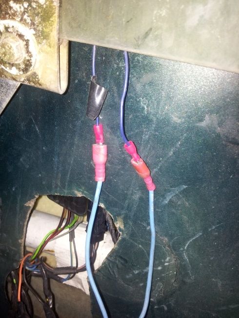
I reattached the patch wires to reach the bottom connectors/door wire loom and gave the spade connections a good filing as they looked quite corroded and plugged them back into the door loom wires:
I pushed the outer door switch and - success! All that then remained was to re-wrap my connectors with tape and reattach the door card which as they say is "assembly is the reverse of disassembly".
Job done. The outer door switch now works perfectly first time every time.
As I said at the start of this guide whilst this is focused on the drivers outer switch the exact same process and logic can be applied to any of the door/window switches or sensors. The process is quite simple first work out if the ECU has a signal, if it does have correct signal then the ECU could be broken. If not then remove and test the switch/sensor in question. If that works too then you have a bad connection somewhere between the two. In my case I had two bad connections from the switch to the ECU and replacing them has solved the problem.
Well it's time to take my own advice. After parking my car up on Saturday following my disappointing MOT experience I needed to move it around on my drive last night. I pressed the drivers door open button and - nothing. The door would not open from the outside. The inside button was fine so I decided I would produce a short guide on how to diagnose and fix these sorts or problems. Although this is specific to the outer door open switch you can apply the same process to any of the sensors/switches related to door/window functions.
I suspected I may have a switch problem over a control unit problem as the button sometime required two or three hard presses to work previously but it always did work. Now it didn't so it was time to fix the problem properly.
Step 1 - Work out if the door control unit is faulty.
Open the boot and locate your door control unit (on top of the fuel tank, on the right). You can leave all connectors attached if you have a multi-meter with small probes. You are interested in the large/long connector and a description of each wire can be found on one of my previous posts here ( http://www.timmason.com/doorecu1.jpg). Put the positive probe onto the 12v positive supply and then the negative probe onto the sensor/switch you are interested in testing. In my case it is the drives door outer switch A7 which is the last orange wire on the first row. You can see the test setup here:
Now it should be reading 0v (or close to 0, say 1.1v or a low reading as some do have a small constant voltage). When the button is pressed it should read 12v. It is helpful to have a helper for this if you are in the boot. Mine didn't change when the button was pressed and to confirm my test was valid I moved the negative probe right one pin onto the next orange wire which is A6 the passenger outer door switch. This had a small voltage and when pressed went to 12v.
Now I knew the fault was with the switch or somewhere between the control unit and the switch but the control unit itself is most probably fine.
Step 2 - Take off the door card.
The door cards are held on by two allen bolts at the front:
Three underneath and three along the rear of the door. Leave the top rear bolt to last to avoid the door card coming away from the door too early and potentially damaging the fiberglass.
TIP: The top bolt on the rear of the door as shown in the photo above is longer than the other two below and must go back into the same location.
As you are undoing the last bolt you will need to support the door card as once it comes away you must unplug this multiplug to remove the card:
Step 3 - Figure out if you have a bad switch or a faulty connection.
With the door card out the way you will see a whole bunch of wires and chances are you are not the first person in here so look out for altered wiring and wire colours. To give yourself a little but more room take out the small door ecu and move it out your way. The try to access the wiring you are left with:
TIP: While you are working on the door now is a good time to check your drain holes are all clear along the bottom of the door (or your door will slowly fill with water and you will be in a world of electrical issues) and fix any rattles. My drives door would rattle when shut and also had a small but not constant rattle when driving. Both these problems are now solved. The rattle when shutting was the small ecu had lost its foam pads that keep it snug and tight in side the door and was rattling around (just glue/tape these back on). The small rattle when driving was down to a bolt and two nuts inside the door which I fished out using a magnet. Obviously they had been dropped inside at some point and somebody couldn't be arsed to fish them out.
My problem was the outer drivers switch and I know this is an orange wire. You can see the orange wire in the pic above that is connected to a much wider blue wire. The black wire next to it is the other wire to the switch. As is usually the case I am not the first person here and somebody has replaced the outer switch in the past.
I unwrapped the tape to find a couple of spade connectors. Next you need to use your multimeter set to continuity testing to find out if the switch is faulty or if a connection/wire is broken. Remember to unplug the connectors before testing the switch, although if you don't all that will happen is when you test the connectors/wires the door solenoid will fire and that might be a good test in itself to confirm the fault is above that point in the wiring and not below.
So, connectors unplugged I noticed I had the same arrangement further up the wiring where the blue patched in wires led to. I unplugged those too and pulled the switch wires through the top access hole to I could test them:
With the probes in place and the switch pressed - nothing still. So not I knew either the switch had broken or another wiring fault further up was the fault.
Step 4 - Removing the outer switch.
The way you can remove the outer switch is to first carefully remove the mirror glass. The mirror glass is help in place in four corners. You need to gently pry away one corner (I started with inner top) and then using a very small flat headed screwdriver you can lift the remaining tabs and pull the mirror glass out. You will also need to disconnect the heated mirror connections to fully remove the glass:
I noticed under the heater mirror connections there was two more connections that go to the door switch. You can see them here with the red crimped connectors:
Those connectors were too small for me to test so I thought before I have to cut them out I would see if I could test the switch itself. To remove the switch you need to unscrew it from the brass nut on the inside of the mirror housing:
The brass nut will not be tight and you can hold it in place with a flay screwdriver and (with the rubber waterproof cover removed) unscrew the switch from the outside:
It turns out you can't test the switch as the wires are molded into the housing and there is no exposed elements to test. I proceeded to open up those red connectors inside the mirror housing and tested the switch from the ends of the wires.
The switch worked perfectly! So now I know it is a bad connection and I do not have a faulty switch.
Some people say you have to remove the mirror motor and housing to put the switch back in but I found it very easy to just hold the brass nut in place with a large flat screw driver and screw the outer switch in just enough to catch the thread. Then just turn the brass nut with the screwdriver until it is nice and tight - no need to remove the motor housing at all.
Step 5 - Fixing bad connections.
What I knew so far is that the switch works. The switch is connected with two inline connectors inside the mirror housing which leads to two spade connectors inside the door. The two spade connectors inside the door have about 8 inches of thicker wire patched in to reach the bottom set of spade connectors. Here are the various bits of wire and connections in my setup:
A) Switch -> B) inline mirror connector -> C) Door wire spade connector -> D) Patch wire spade connector -> E) Door wire loom -> F) Boot ECU
At the switch side of connection A->B I have continuity but at the first connector side B->C I don't. Easy fix then - I replaced the inline connectors in the door mirror and rested the spade connections at point C:
Still nothing!!
OK, perhaps the spade connectors are at fault - I cut them off and put on new ones as I was staring to lose the light and wanted to get the job finished and sure enough the new connections worked.
I guess I had two faults in the wiring then. One in the inline connectors inside the door mirror and another in one of the first set of spade connections.
I reattached the patch wires to reach the bottom connectors/door wire loom and gave the spade connections a good filing as they looked quite corroded and plugged them back into the door loom wires:
I pushed the outer door switch and - success! All that then remained was to re-wrap my connectors with tape and reattach the door card which as they say is "assembly is the reverse of disassembly".
Job done. The outer door switch now works perfectly first time every time.
As I said at the start of this guide whilst this is focused on the drivers outer switch the exact same process and logic can be applied to any of the door/window switches or sensors. The process is quite simple first work out if the ECU has a signal, if it does have correct signal then the ECU could be broken. If not then remove and test the switch/sensor in question. If that works too then you have a bad connection somewhere between the two. In my case I had two bad connections from the switch to the ECU and replacing them has solved the problem.
Edited by TimJM on Tuesday 15th April 12:00

Thanks - I'm just trying to put something back for all the help I have received on here. You will have to forgive the few typos in there - I typed most that up late last night before uploading the pics and posting it at lunchtime today.
Little jobs like this any owner can do with the right information and whilst a specialist may only charge £60-£120 for a similar fault (depending on where you go) all it has cost me is about 10p worth of connectors, a dab of solder, some insulation tape and an hour of my time.
Little jobs like this any owner can do with the right information and whilst a specialist may only charge £60-£120 for a similar fault (depending on where you go) all it has cost me is about 10p worth of connectors, a dab of solder, some insulation tape and an hour of my time.
Public fora are full of many types of articles - that's what they're there for. Whether they're good or bad largely depends on the observer's tastes and own desres
BUT
It's people like you, Tim, who dedicate so much of their time and energy into helping others that enable individuals, stuck out in the back of beyond, to run the most beautiful cars that they will ever own.
Thanks very much from one such (little) owner
BUT
It's people like you, Tim, who dedicate so much of their time and energy into helping others that enable individuals, stuck out in the back of beyond, to run the most beautiful cars that they will ever own.
Thanks very much from one such (little) owner
Also, to eliminate the possibility that the ECU is causing the problems disconnect it completely. Then repeat the test. If you still have a constant 12v with the switch pressed/unpressed then you must have a wiring fault as that is wrong and it can't be the ECU if it isn't connected.
You can test and control all the door/windows functions without the ECU attached by just feeding the motors/actuators 12v. Be careful though, if you are blowing a fuse you must have read one of the wires wrong on the wiring diagram color codes/pin position and you are shorting something out.
You can test and control all the door/windows functions without the ECU attached by just feeding the motors/actuators 12v. Be careful though, if you are blowing a fuse you must have read one of the wires wrong on the wiring diagram color codes/pin position and you are shorting something out.

TimJM said:
Also, to eliminate the possibility that the ECU is causing the problems disconnect it completely. Then repeat the test. If you still have a constant 12v with the switch pressed/unpressed then you must have a wiring fault as that is wrong and it can't be the ECU if it isn't connected.
You can test and control all the door/windows functions without the ECU attached by just feeding the motors/actuators 12v. Be careful though, if you are blowing a fuse you must have read one of the wires wrong on the wiring diagram color codes/pin position and you are shorting something out.
I will disconnect the ecu and retry now.. I can't really get the 12v to the windows wrong, they are the only 1.5mm dia wires there! So the window should go up or down.. I have chased the wiring through the diagrams and it matches the car..You can test and control all the door/windows functions without the ECU attached by just feeding the motors/actuators 12v. Be careful though, if you are blowing a fuse you must have read one of the wires wrong on the wiring diagram color codes/pin position and you are shorting something out.
Jhonno said:
With the ECU disconnected I get 0v... Reconnect and I get 12v for the window drive..
Windows drive - do you mean the outer (and/or inner) window switch?If the wiring is behaving as it should without the ECU attached but doesn't behave correctly with the ECU attached then I would suspect a problem with the ECU.
Have you had the ECU checked?
These are (from what I have heard) fast and sensibly priced:
http://pselectronicsolutions.co.uk/
steviejasp said:
Mine has developed a fault today.
I tried step 1 and I only get 2.6v when button is pressed. Does that indicate faulty ecu? Inner door button works fine though. Any ideas please?
If you only get 2.6 volts this will almost certainly be down to corroded connectors or if you are unlucky a break in the wire. I would take the door card off and check to see if you have spade type connectors as I did spliced in. If so could be the cause. Or you could have some connectors in the door mirror unit again as I did that are corroded. The only way to test is to take a look and see what you have.I tried step 1 and I only get 2.6v when button is pressed. Does that indicate faulty ecu? Inner door button works fine though. Any ideas please?
Gassing Station | Cerbera | Top of Page | What's New | My Stuff