4.2 Bodyoff Rebuild
Discussion


gruffalo said:
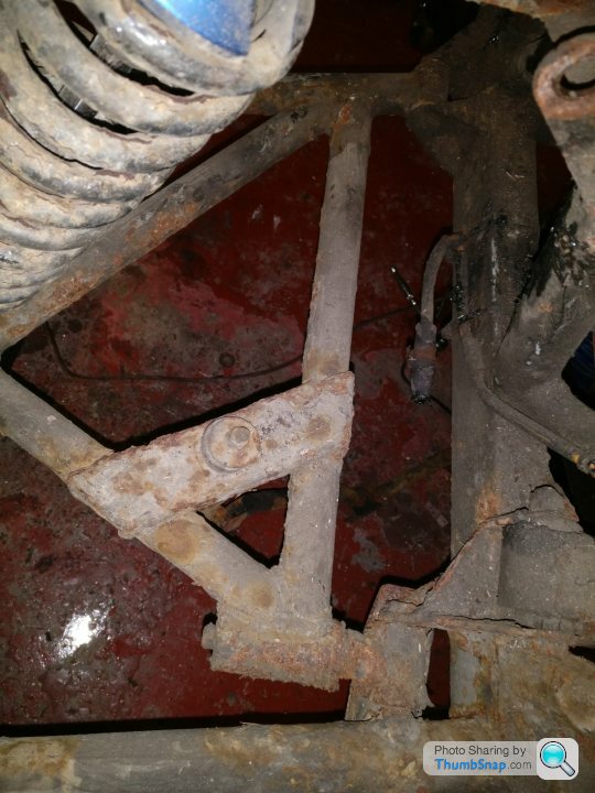
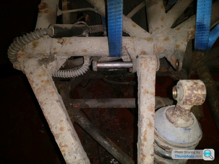
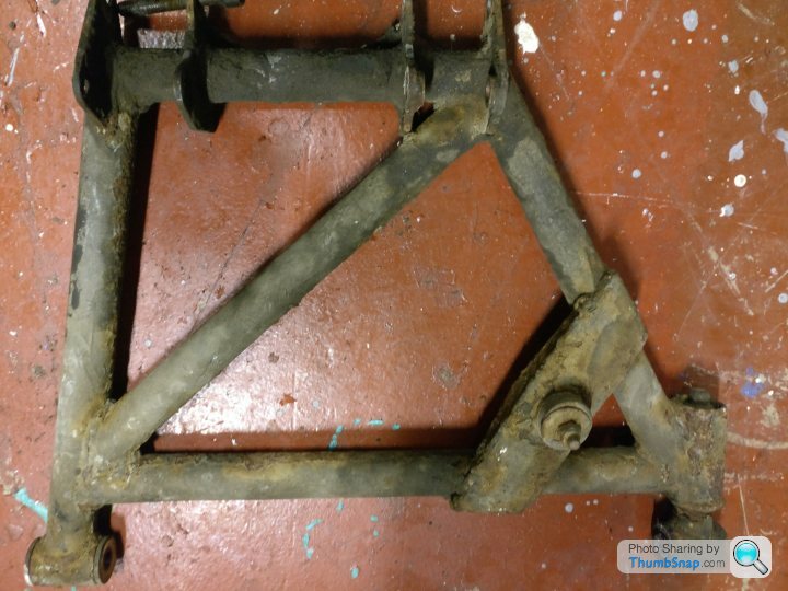
Why the change to the rear wishbone, what will it achieve?
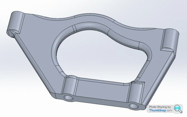
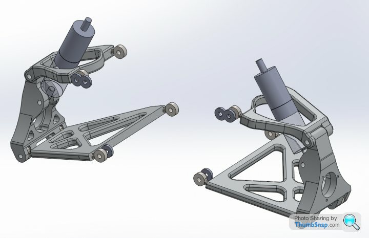
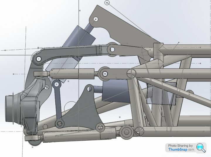
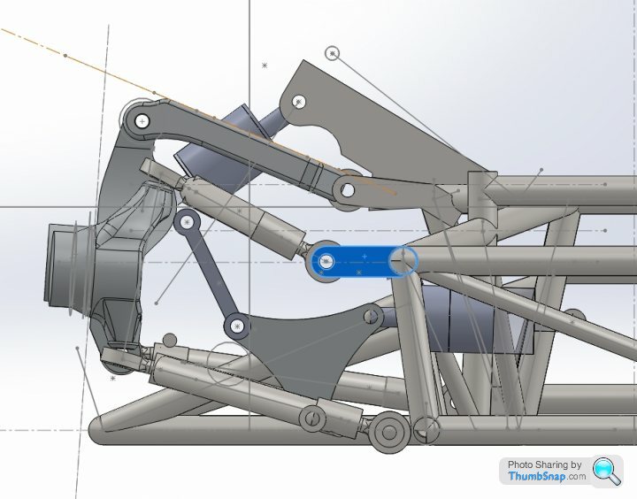
Hi Gruffalo. Well I have changed the design again slightly last night after drawing till 5am which I now slightly regret! But the idea is to move the pickup point of the upper wishbone forward, by my measuring there is over 100mm to play with, this will allow me to attach the spring/damper directly to the upright at a central point just above the driveshaft, there is also a new pick up point for the shock on the chassis.
I just about got there with an upright and lower wishbone, once I modify the upper and finish modelling the upright I'll post up an assembly for scrutiny.


gruffalo said:
Interesting, what will you gain by this?
I have been looking at ways to get the spring and damper more vertical to improve compliance and therefore ride and grip.
Sure, as you mention, increased control of rear suspension, less flex in assembly and wishbones. Spring will be acting in correct plane relative to wheel. I have decided to draw up the chassis also, i'm half way through! It's a little tricky, but it means that in theory all chassis spars can be cut to exact length and angle etc without having to measure and eye it up. Should have tighter joints and less messing about. The chassis will all be tig welded anyway so the joints could do with being tight!I have been looking at ways to get the spring and damper more vertical to improve compliance and therefore ride and grip.
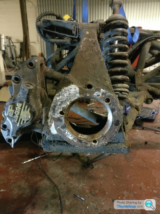
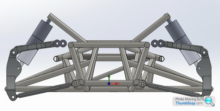
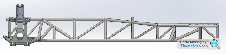
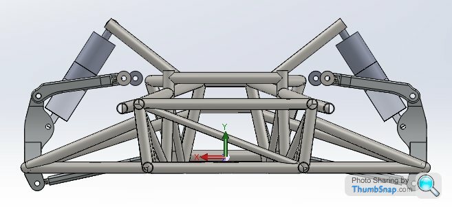
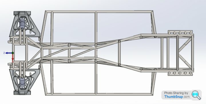
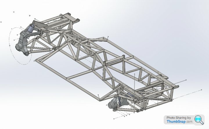
So, today I have got the diff out of the chassis, bolts were siezed it took ages. I have continued with the chassis drawing and have attached some pics below. I have also started to cut some tubes up, the ones in green are the ones i've done today, I got 12 cuts out of the holesaw. No pics as I left my phone at home. This is pretty much what a cerb chassis looks like, except for the additional spars at the front by the upper suspension pick up. I'm not sure it'g going to look quite like that, but it wont be like the TVR version either. I'm modelling up the front suspension next, and it will be slightly different with wider wishbones and again i'm relocating the shock mount just slightly.
One major change I have made is replacing the bottom rails with tube instead of box, so the rear lower outrigger sits slightly lower on the central tunnel. I have only roughly done the suspension mountings so that may look a bit different. The tunnel section of the chassis I also plan to gusset with 1.2mm steel to try to reduce the twist which will occur with such a narrow structure. The steel I am using is ropt510 and it is at least 2.5 times stronger than original. I am using 2mm and 2.6mm wall thickness and the chassis is coming in at 87kg with mostly 2.6 tube, and the additional support for rear shock. There are still some additional spars to go in to support this also. Does anyone know the weight of the original chassis?
I have also added in 2 spars where the front roll bar is, I am going to re site and re design the roll bar. Possibly make it adjustable in car.
One picture also shows the amount of planes that I needed to be able to create the chassis model, over 100.
Thanks for the comments, I have really enjoyed the last 4 days, I wont have quite so much time to spare now though.
NuddyRap said:
I'll be following this with interest.
I know a good number of CAD packages myself (Autodesk mainly) and the only reason I haven't started doing something similar is because I haven't been able to find anywhere to put the car to work on it and take it to bits!
I've really wanted to model the chassis and then seek consultation on some ideas I've had for building something lighter and more robust to see if they're viable.
I then wanted to model the body properly but first, I need to find a unit in the midlands-ish. Apparently none exist, and you're in Wales right?
Good luck, looks like good work.
Thanks, yes I'm in Wales, luckily my business moved into a unit with ample space at the moment so I can do it. I know a good number of CAD packages myself (Autodesk mainly) and the only reason I haven't started doing something similar is because I haven't been able to find anywhere to put the car to work on it and take it to bits!
I've really wanted to model the chassis and then seek consultation on some ideas I've had for building something lighter and more robust to see if they're viable.
I then wanted to model the body properly but first, I need to find a unit in the midlands-ish. Apparently none exist, and you're in Wales right?
Good luck, looks like good work.
If you used T45 tube or 4130 I think you could save 25kgs with replacing the bottom rails.
I havent tried to save weight over original although the bottom spars save a fair bit, but I've added it back in. My aim is for a much more rigid chassis.
Little progress update, have finished the suspension geometry now, got a little tidying to do with brackets and spars in the front but pretty pleased. Front upright design also. I think ill do the wishbones out of tube. I'm about to start drawing bells for the front and rear so that I can use bolt on rotors. Front shock arrangement gives a rising spring rate. Few pics below.


Jonbouy said:
How are you going to fabricate the chassis and components
For the wishbones I will make jigs, bolted where they need to be for geometry then Tig welded. I will soon be starting on the chassis jig, I will make it on reverse on my chassis basically,allowing for the suspension changes I am making. I am still playing about with finer details on suspension, I want to explore every option before committing to it. The rear is pretty much there now as are the chassis alterations.
The front I think the pull rod arrangement works, but taking into account the kpi and length of upper and lower wishbones, I think I'd prefer a pushrod. So I'm working on that to see which option is best, it may be a case of having spring direct as per original with different attachment points. What I am trying to do is reduce the load on the suspension so I can reduce weight and increase strength. I'm hoping to have this finished tomorrow.
I still have to site the calipers on uprights, I'm ordering disks e.t.c shortly.
The machined components are relatively easy as I have access to cnc.
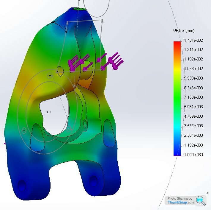
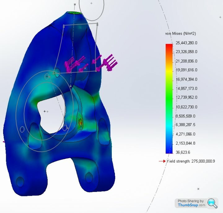
So I'm still working on the suspension models but maybe 95% there now. Tonight I have ordered all the parts I need to buy for suspension. My uprights have changed a little, I have saved 1kg off the rear and could go for more. Below are some basic stress analysis simulations. I have a factor of safety of over 10 on each upright with between a 2000kg and 3000kg loading, so very safe, although it is a very simple analysis. Loading on rear is 500kg on each bolt point from bearing, 500kg on face of upright and 1000kg on shock pickup. Front is 500k per bolt and 1000kg on face. These loads are clearly in excess of what you would get on the road. Material was 6082T6 which is cheap and easy to get, but I do have some blocks of 7075T6 which I may use, and that is significantly stronger, but doesn't hold up to fatigue so well.
I will add in mounting points for calipers and steering on front in the next few days. I was going to go for my own stub axle on the front with bearing set in the upright, but I figure for time it is easier to use existing bearing setup.
I cut a few more tubes today ready for new chassis, still yet to start on the jig. I did cut the existing chassis in a few places to inspect and it's much better than I thought. It is all light surface corrosion. I guess I will have it blasted, then repair if needed, and powder coat, have no plans for it but may need it for something. Or I would be willing to sell I suppose.
Braking is getting an overhaul, 6 pots on front, 4 on rear, hubs and rotors but not floating i'll go for solid bolted. As I've mention I don't like the pedals and have that figured out, will post pics when ready. I have an hour spare tomorrow so will do a bit more on the chassis. My AP units will be surplus to requirements.
FarmyardPants said:
I could model the chassis in Solidworks, but wouldn't be able to do anything with said model other than spin it around and look at it (and run some stress simulations).
How do you plan to use your models, do you have access to CAM machinery that can mill parts from them?
The pics look great!
Yes I have a 4 axis cnc luckily. How do you plan to use your models, do you have access to CAM machinery that can mill parts from them?
The pics look great!
Sure, the uprights are relatively simple. For front will cut dovetail on one side of stock, then clamped into a 5 axis vice, which gives you clearance on all other faces. First side will be the outside of upright, normal cutting and contouring, will use the bolt holes initially reamed to 6mm, can then flip part and locate accurately with out clocking in. This side then finished, which will leave lower ball to do which is no problem as its perpendicular, upper is angled 9 degrees I think off the top of my head, so will need to make a jig for this. Then back on to front and take the 6mm up to clearance. Fairly similar for rears.
Jonbouy said:
wow, just my type of reading, some real interesting engineering designs and processes, would love to be able to operate and design components in CAD. scerbera, have you worked any costings out? I must cost a fair bit for a solid block of aluminium?
Great thread.
Thanks, the front billet is around £85, and rear probably £120 for the raw stock. That would be 6082T6 which is very common and a good material. I will post up some videos when I machine the uprights.Great thread.
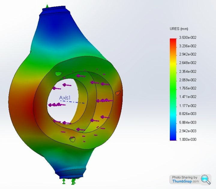
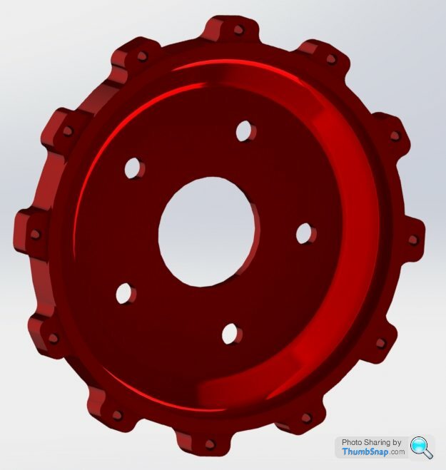
This evening I've modeled my front bell for the discs I'm going to use. I think I will get these anodised red to match the car, not this red exactly but you get the idea. Bore hole is incorrect i'll measure bearing tomorrow. I'll also probably pull the taper in earlier to reduce a little more weight.
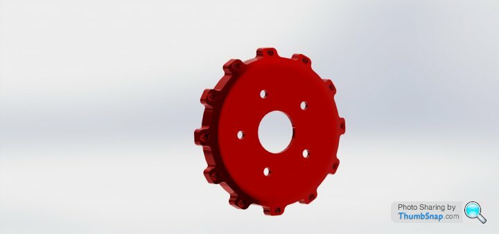
Edited by scerbera on Wednesday 18th January 00:50
julian64 said:
Just a quick question, and I could be wrong as my abilities with solidworks aren't anywhere near as good as yours.
The upright you have done stress analysis for shows a lateral force applied evenly.
When I have done this in solidworks (not with an upright, but modelling other components) the bit that kills me is the bolt holes. And its the bolt holes that seem to be the bit that it always breaks at as I increase the force. From the pattern you have it looks like you haven't fixed the bolt holes for your stress analysis so you don't have the red warnings all around the bolt holes that I get. Is there any reason you've done it like that?
For some reason the arrows indicating force on the bolt holes aren't in the picture, but they are there. For the front I put 10000N on the face which, then 5000N pushing upward on each bolt hole, it's hard to model as the bolt doesn't act on it like that, but it's probably near enough to get an idea.The upright you have done stress analysis for shows a lateral force applied evenly.
When I have done this in solidworks (not with an upright, but modelling other components) the bit that kills me is the bolt holes. And its the bolt holes that seem to be the bit that it always breaks at as I increase the force. From the pattern you have it looks like you haven't fixed the bolt holes for your stress analysis so you don't have the red warnings all around the bolt holes that I get. Is there any reason you've done it like that?
My fixed points are the bolt hole top and bottom. I'm not sure how to go about modelling dynamic stress, but this is 2500kg going through it and has a factor of safety of 10.
For the rears same setup, but I also have 10000N on the shock mounting. If you look again at the rear von mises pic you can see some red around a lower bolt hole.
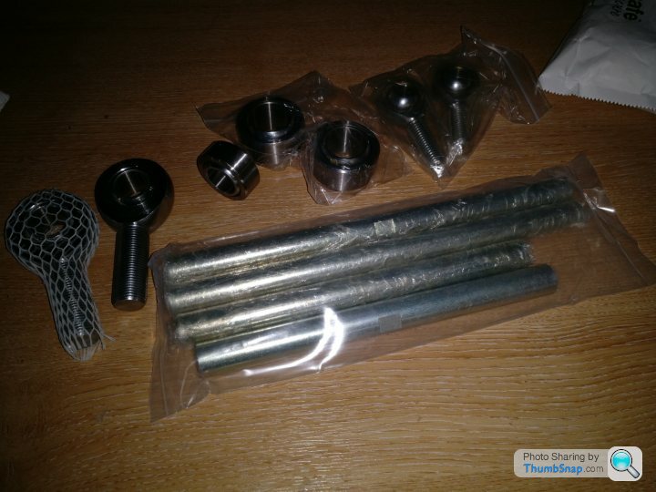
Yesterday my rod ends and spherical balls arrived for suspension so can make a start on that when time permits!
I have ordered 309/21 discs for rear and 331/32 for front. Also some bits to rearrange pedals, I need to see if it's going to work, I think so according to my measurements.
I do have a question for anyone reading with prior knowledge, if I go for 4 pot at rear and 6 pot at front, will I need to change master cylinder bore? Or does anyone know typical distance before pad engagement?
Also I am unable to find the power assist ratio for the brake servo, does anyone know what it is?
Poopdog said:
What are you doing with the pedals then?, like you I'm not keen on my pedals either as in my case they just feel wooden and cumbersome , what make calipers are you going for then?
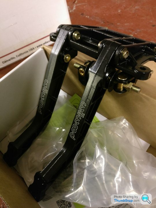
Ah well, I was going to go for Wilwood, and I may still, but last night I decided to draw a caliper, which I've done and I'm happy with it, so the rear is done. I'm going to use a wilwood pad, something like 120*62 for rear, and 150 wide on the front. Hoping to draw that tonight.
I've ordered a pedal box as it's not too dear to justify, a wilwood unit, there appears to be plenty of room if you take the existing structure away. I will probably modify it, add appropriate brackets for new pedals and refit.
The brake is a double master cylinder with a bias bar so I can dial in the brake balance. The master cylinders will be easily accessible I believe, they are further inside the cabin, as will clutch master be.
I plan to run remote servo unit in place of existing unit.
For throttle I will also be moving and changing action, I don't like the throw of it at all. It will be shorter.
Thanks for kind comments. I'm open to making things for people once I've put this together so I guess we will have to wait and see how it turns out.
A few bits arrived today, braking parts and pedal box. I have nearly managed to get the existing pedal assembly out, the new one will fit great and make everything more accessible. The brake is dual master with bias bar.
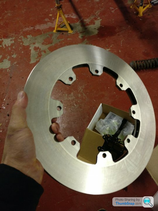
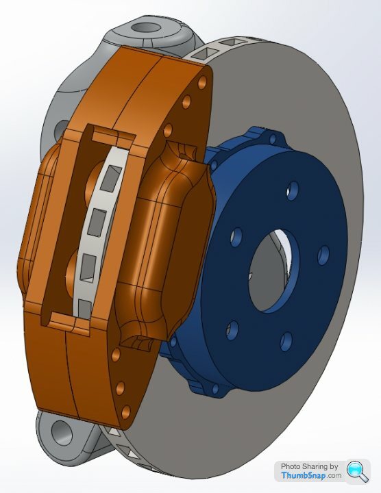
I've done a little assembly of the rear upright with caliper, disc and bell. The new rear pads are enormous compared to standard, possibly 3* as big, around the same size as existing fronts, I'm pleased I have the bias bar pedal setup to account for these changes.
My front discs and pads are a week away from delivery and so although I have drawn the front caliper, after measuring the rear pad tonight I've made a fair few changes so I'll wait for pads before finalising front design.
A selection of spherical balls in one pic, and some machining I did today non TVR related on the 4th, cutting some cam profiles.


A few bits arrived today, braking parts and pedal box. I have nearly managed to get the existing pedal assembly out, the new one will fit great and make everything more accessible. The brake is dual master with bias bar.
I've done a little assembly of the rear upright with caliper, disc and bell. The new rear pads are enormous compared to standard, possibly 3* as big, around the same size as existing fronts, I'm pleased I have the bias bar pedal setup to account for these changes.
My front discs and pads are a week away from delivery and so although I have drawn the front caliper, after measuring the rear pad tonight I've made a fair few changes so I'll wait for pads before finalising front design.
A selection of spherical balls in one pic, and some machining I did today non TVR related on the 4th, cutting some cam profiles.
Gassing Station | Cerbera | Top of Page | What's New | My Stuff