Getting the most out of the Throttle Bodies
Discussion


As part of my on-going development i want to see how i can get the most possible out of the throttle bodies. The simple awnser would be to buy some nice roller barrels, however there would be no fun in that!
So me and Julian64 have teamed up to see what we can do. We spent some time today disscusing the best routes to take.
I would like to hear everyones views on this topic and we also had some questions.
Firstly, at the bottom of the throttle bodies there is a slight curve rather than just going straight to the inlet. Why? It must have been done for a reason. If this was removed could it have any negative effects?
The top of the throttle body is 45mm and 40mm at the bottom. The inlet is also 40mm. Is the narrowing an important factor? i.e should the top allways have a larger diameter than the bottom and why?
We dont want to do the standard port and polish, we want to see just how good we can make them. This could involve machining them to far! Due to this is was wondering if anyone has any broken or scrap throttle bodies? The same with a head. How damaged they are really dosnt matter!
Lastly, anything you think we should try!??
Cheers
Mike
An interesting starting point is to fit them the wrong way round on the wrong banks, injectors on the outside. They are then much straighter into the port. Of course it means some work on the throttle linkage and plate angles but it could be beneficial in terms of straightening the air path both from the bodies into the head but also the transition from the intake pipes to the bodies. I was forced to do it on mine but once I actually fitted them this way it looked immediately clear that this was how they should have been in the first place. This also allows a better injector angle pointing more down the port rather than spraying onto the back wall of the throttle body.
If you want to go this far I think the engine could also benefit from dual injectors, one set above the throttles, standard position and a second set below for better idle and midrange. Not sure if this is practical though, not much room down there.
If you want to go this far I think the engine could also benefit from dual injectors, one set above the throttles, standard position and a second set below for better idle and midrange. Not sure if this is practical though, not much room down there.
 I look forward to reading this topic.
itsallyellow said:
The top of the throttle body is 45mm and 40mm at the bottom. The inlet is also 40mm. Is the narrowing an important factor? i.e should the top allways have a larger diameter than the bottom and why?
I presume that the narrowing is there to speed up the airflow, as in the Venturi effect (Bernoulli’s theorem)Anyone calculated reynolds numbers for the inlet tract on a Cerb to find out if there is any laminar flow anywhere in a Cerb inlet tract?
I have a theory that the kink at the bottom of the inlet tract was a nod to causing laminar flow breakup for fuel mixing prior to the inlet valve.
However as far as I have been able to calculate there is no laminar flow possible anywhere in the inlet tract.
So I'm currently working on the theory that wide as possible for as long as possible, and the kink at the bottom of the inlet tract is theoretical not practical, and as a general part of
widening the 4.5 throttle body
straightening the 4.5 throttle body
and removing the butterfly rod from the thinned butterflys
jobs an improved one.
Just a thought...
Could a major player in engine tuning/building not be of some use here?
Why not get a load of owners to club together, and send a head and some TBs to somewhere like http://www.swindon-engines.com/design/index.html
They do some work, scan it in 3D, then if anyone else wants it done, they have the template ready, stick it on the machine and it can be done relatively cheaply (economy of scale)
Just a thought.
I've got a design in my head for something very high flowing but would impact (i suspect ut don't know for sure as i've not built it yet) on the bottom end/town driving and if anyone wanted to come on board for development/testing they would be sworn to secrecy until such time as we were ready to launch so on that basis it's probably not what mike would want on his car as that's too public a car and he dosn't want to impact on the lower rev range .. but if anyone else wants to come on board for development that would be cool. PM me through my profile if you're a track day cerb owner and you're looking for top end gains and don't do much town driving lol
 [IMG]
[IMG]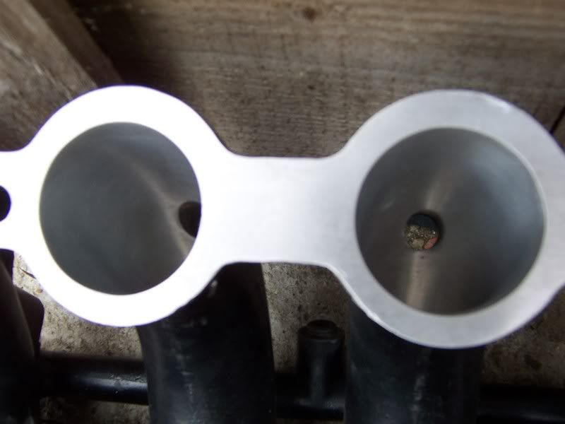
If you want good mid range my feeling is to approach it the other way around - what's the smallest butterfly I can get away with and still make the power I want? Jenvey state their 42mm throttle body as giving up to 56bhp in their FAQ, for the AJP that'd 448bhp, they also mention that another 10% is possible for well designed systems. Ok their test conditions don't quite match what you want to do but it does suggest to me that getting the size just big enough is going to make a bigger difference to you than making everything as big as poss.
Edited by Steve_T on Friday 15th May 12:38
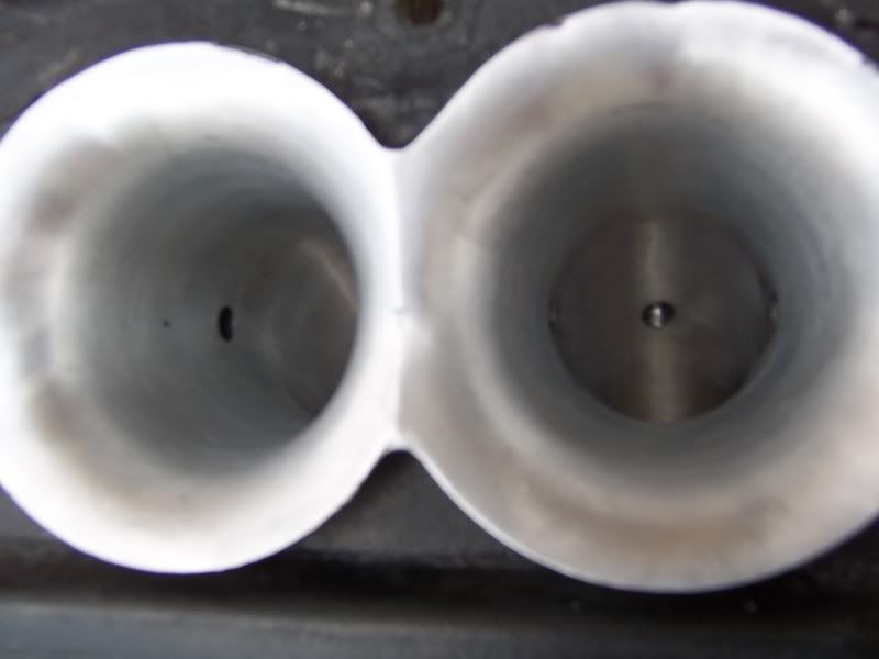
They look beautiful Ian .. hope youve not touched the butterfly area though  I'm assuming with all the work that you're trying to get as much from the 4.2 manifods as possible? My experience on the flow bench suggests that once you've taken out the final narrowing and the step upstream and thinned teh spindle there's nothing else to come from putting the flap wheel down the whole length of manifold, does look pretty though and your standard of work is impeccable, I hope the air appreciates it, lovely job
I'm assuming with all the work that you're trying to get as much from the 4.2 manifods as possible? My experience on the flow bench suggests that once you've taken out the final narrowing and the step upstream and thinned teh spindle there's nothing else to come from putting the flap wheel down the whole length of manifold, does look pretty though and your standard of work is impeccable, I hope the air appreciates it, lovely job spitfire4v8 said:
It's very possible julian, in fact its already being done by a company making throttle bodies though i forget the name of the company, they advertise in PPC magazine
They don't conveniently say how they do it, do they though i forget the name of the company, they advertise in PPC magazineI have three running possible theories at the moment as to how you would create a Cerb based spindle less throttle body, but they all require some quite ticky machining, which would be either right on my limits or a few feet past them.
I want to simplify somewhat.
But, and this is only a guy feeling, that thereby lies the best improvement that could be gained on the thottle bodies. I even think that would give you better gain that widening 1-2mm.
Have a chat with Mike, we've just chatted on the phone. I think it would be good for you to try and get as much from the std arrangement as possible as no-one has really tried it yet to my knowledge. I'm going ahead to make my own inlet arrangement and we'll meet up at some point to try them back to back
indeed, one of the points he stressed on the phone was the desire to keep it a development of the existing induction rather than the complete rip-out and replace with something completely different that i was proposing. As an AJP fan i fully understand where he's coming from, although i have not as much allegiance to the std throttle bodies and would very much like to try something radically different
http://atpowershop.co.uk/catalog/42mm-dcoe-throttl...
I have to say though that is so cheap, and for that cost they'll machine you the plate to your cylinder head. I couldn't buy the stock to machine for that price.
I don't see how you could beat that.
If mike came anywhere near a 7% increase in flow to his cylinder head he'd be in a 500bhp AJP
I have to say though that is so cheap, and for that cost they'll machine you the plate to your cylinder head. I couldn't buy the stock to machine for that price.
I don't see how you could beat that.
If mike came anywhere near a 7% increase in flow to his cylinder head he'd be in a 500bhp AJP
Edited by julian64 on Friday 15th May 13:59
Gassing Station | Cerbera | Top of Page | What's New | My Stuff