Distributor alternative?
Discussion


The easiest, quickest, but not the most reliable way to build an astable multivibrator to trigger an automotive coil is to use a relay, that has two sets of contacts, like most automotive ones. Wire the relay coil and the ignition coil via the normally closed contacts. When you apply 12v, current will flow through both the relays operating coil and the ignition coil. After a few ms, the relay will energise, opening the normally closed contacts, cutting off power to the two coils. This causes the coil to generate a spark as it's current collapses, and the relay will cut it's own power off, and hence close the contacts again. This repeats about 20 times a second, whilst the relay contacts last (eventually, they will burn themselves out)

A coil chucks out about 300 volts in the primary when the points open- this is why you have a condenser across the points to provide a path for this spike- this will destroy semiconductors, and will cause severe arcing across relay contacts. A much better bet is the Velliman Electronic coil trigger kit- it costs very little and works really well. It will take care of all the spikes and current involved when switching a coil. This would work a treat with Max Torques suggesting of using a relay as a "buzzer" to provide the pulse steam to fire the amp. You could also probably get the amp to fire directly from the 555 timer kit, by passing the relay completely and connecting the amp input in place of the relay coil. No nasty mechanics involved to go wrong.
https://www.esr.co.uk/velleman/k2543.htm
https://www.esr.co.uk/velleman/k2543.htm
Edited by blitzracing on Sunday 18th January 18:35
blitzracing said:
A coil chucks out about 300 volts in the primary when the points open- this is why you have a condenser across the points to provide a path for this spike- this will destroy semiconductors, and will cause severe arcing across relay contacts. A much better bet is the Velliman Electronic coil trigger kit- it costs very little and works really well. It will take care of all the spikes and current involved when switching a coil. This would work a treat with Max Torques suggesting of using a relay as a "buzzer" to provide the pulse steam to fire the amp. You could also probably get the amp to fire directly from the 555 timer kit, by passing the relay completely and connecting the amp input in place of the relay coil. No nasty mechanics involved to go wrong.
https://www.esr.co.uk/velleman/k2543.htm
The role of the "condenser" in a mechanical "breaker" system is to act as a low DC impedance for a short time period to ensure the points are well separated before the primary current is completely stopped. If you don't have one, the picosecond the points open, the current is interrupted completely, and as V = L di/dt, that generates a huge voltage across those points, resulting in local ionisation in the (small)gap, breakdown, and an arc across those points, resulting in rapid wear of the contacts and also a huge RF emission (which used to interfere with your car radio!). https://www.esr.co.uk/velleman/k2543.htm
Edited by blitzracing on Sunday 18th January 18:35
With the condenser in place, at the moment the points open, current can briefly (~300uS) continue to flow through the condenser (which is effectively a DC "short" when discharged). Then, when the condenser becomes fully charged, it cannot transfer any more current, and becomes effectively high impedance to the DC current flow, stopping that current flow, and allowing the coil to generate the high voltage (via "Flyback" caused by the tightly coupled windings in that coil). However, at this point, the points have had just enough time to open enough to avoid an arc occurring across them. When the points re-close, ready for the next firing event, those points short out the condenser, discharge it, so it is ready to protect the points for the next opening.
It's really quite an elegant solution ;-)
Edited by anonymous-user on Sunday 18th January 19:44
Edited by jeremyc on Tuesday 20th January 13:03
Doctor Volt said:
blitzracing said:
A coil chucks out about 300 volts in the primary when the points open- this is why you have a condenser across the points to provide a path for this spike- this will destroy semiconductors, and will cause severe arcing across relay contacts. A much better bet is the Velliman Electronic coil trigger kit- it costs very little and works really well. It will take care of all the spikes and current involved when switching a coil. This would work a treat with Max Torques suggesting of using a relay as a "buzzer" to provide the pulse steam to fire the amp. You could also probably get the amp to fire directly from the 555 timer kit, by passing the relay completely and connecting the amp input in place of the relay coil. No nasty mechanics involved to go wrong.
https://www.esr.co.uk/velleman/k2543.htm
this is why you have a condenser across the points to provide a path for this spike????????https://www.esr.co.uk/velleman/k2543.htm
Edited by blitzracing on Sunday 18th January 18:35
Unbelievable comments and advice being posted to this topic
AER said:
Never mind that such a device already exists in the aviation industry and is known as a "shower-o-sparks" module.
Don't be ridiculous! The fact that a device, exactly as i described it, exists, and has been used for over 60 years in the aircraft industry is simply not enough evidence. It's quite clear, according to the Good Doctor, with exactly no evidence, or science, or it would seem understanding, that this "sparks" device is impossible and will not work (and hence must be magic or woo-woo).It's also quite clear that even though basic physics explains how an automotive ignition coil works, and that its response can be proven, via that very same physics, to match the theoretical understanding of the component, this is also insufficient for the Doctor.
Far be it for me, a simple chief engineer with only 20 years automotive development experience on multiple platforms across numerous projects, and i, who earn a mere six figure pittance from supplying my clearly unskilled services, must be hood winking all the people who employ me, and by associations, it must be just pure fluke that the projects i work on are extremely highly regarded and received critical acclaim, to tell the Good Doctor how a device works when he quite clearly knows so much better and has made such an effort to explain to us all why we are so very wrong.......
Edited by jeremyc on Tuesday 20th January 13:09
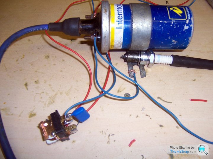
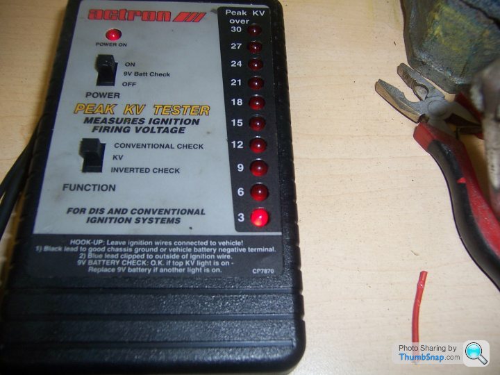
Well here it is- a relay, capacitor and coil as per max torque and may I say it WORKS a bloody treat- Just in case you cant see the spark with my dodgy old camera, you can see the HT monitor showing 3kv- It needs a bit of refining as the relay cycle is very rapid- id say about 60 Hz so it needs a a big electrolytic across the relay coil to slow the switch rate down a bit.
Time for the quack doctor to go back to practising his voodoo elsewhere methinks.

Time for the quack doctor to go back to practising his voodoo elsewhere methinks.
blitzracing said:
Well here it is- a relay, capacitor and coil as per max torque and may I say it WORKS a bloody treat- Just in case you cant see the spark with my dodgy old camera, you can see the HT monitor showing 3kv- It needs a bit of refining as the relay cycle is very rapid- id say about 60 Hz so it needs a a big electrolytic across the relay coil to slow the switch rate down a bit.
Time for the quack doctor to go back to practising his voodoo elsewhere methinks.
Solder a nut or similar weight to the relay switching tag, and that extra mechanical inertia will bring the switch frequency right down (and give bigger sparks as the coil current will be larger at contact opening)Time for the quack doctor to go back to practising his voodoo elsewhere methinks.
Pupp said:
All this so a knackered Stag can impersonate a potato cannon... 
Yup it's all got a bit serious. The OP will probably get something working soon. Just for a laugh and because he could.

Nobody said that the Stag was knackered, it might be a minter.
Thanks to Max Torque for your post about using a relay. Usefull info.
Edited by cold thursday on Tuesday 20th January 00:32
cold thursday said:
Nobody said that the Stag was knackered, it might be a minter.
Yes, the Stag is not knackered, thanks to this young lad trainee mech who loves his cars. Sometimes people just assume, to suit their chosen punchlines.I have found a circuit that will work and have ordered the necessary parts. You were right about the MOSFET CT. Thanks. It's a good chance for the lad to have a go at making his first circuit and understanding rudimentary electronics, supervised of course.
I didn't bother mentioning this as the thread seems to be in the toilet for no good reason now.
For those who contributed constructively to this thread, thank you.
Cad
Gassing Station | Engines & Drivetrain | Top of Page | What's New | My Stuff