The geometry of cam / follower systems
Discussion


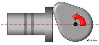
After this topic popped up in a recent thread I thought I'd write a brief article to explain the salient points. The majority of engines are either pushrod and rocker (old skool), overhead cam and bucket or cam lobe sliding on a finger follower (Ford Pinto).
The key thing about a round follower is it has to rotate to survive. This evens up wear and allows the cam lobe to bed into the follower and let both items work harden.
Pushrod engines have followers that tend to be in the 3/4" to 7/8" diameter range. Cam lobes are generally half an inch wide or so to generate sufficient stiffness. To rotate the follower the cam lobe has to operate on one side of it. With a follower 3/4" diameter and a lobe 1/2" wide even if you position the lobe right on one side of the follower some of the lobe is acting on the opposite side of the follower and trying to spin it back in the opposite direction.
To counter this pushrod followers are made with a very small convex radius on the top surface. Generally about 1 metre radius of curvature or 2 metres diameter. This gives the follower a dome about 2 thou high which can only be detected against a good straight edge. To run against this the cam lobe is ground with a very small angle from one side to the other, also about 2 thou high from side to side. This angle runs against one side of the dome of the follower so that any part of the cam lobe that extends to the other side of the follower doesn't contact it. This ensures all the forces make the follower spin in one direction.
With overhead cam engines the followers can be much larger in diameter. Normally between 25mm and 40mm diameter. A normal sized cam lobe can sit entirely on one side of the follower. This now means a flat cam lobe can spin the follower one way only if it's positioned entirely on one side of the follower.
So overhead cam engine followers are dead flat and can be resurfaced on a grinder or flat plate with a sheet of wet and dry paper if they have any wear. Pushrod followers are not repairable which is why they have to be replaced with new ones every time you change the cam.
Finger followers have a hard life and unless made of carbide or chill cast iron they tend to wear out steadily over time because the cam lobe wipe area is basically over the whole area of the follower. They also have to be replaced with the cam every time a change is made.
If any points are unclear I'll expand on them.
Edit 15th Feb.
I'll just add a couple of points about grinding cam lobes for domed followers. Firstly it's obviously vital that the small angle ground on the cam lobe runs the correct way in relation to the dome on the lifter and this depends on which side of the lifter the cam follower sits, at least from the perspective of the guy grinding the cam and which way round he's got it held in the grinder. So he has to know the layout of the components in the engine block and for every type of cam he grinds he'll have a spec sheet which says either no lobe angle for OHC engines with flat lifters or it'll say lobe angle runs left to right or right to left and specify how much angle is to be used.
Secondly how does one actually grind an angle across the surface of a cam lobe. That's really easy. You grind the angle into the cam grinder abrasive wheel first. The grinding wheel is dressed with a diamond tipped tool and on a cam grinder the angle at which this traverses the wheel face can be adjusted from parallel for flat tappet cams to sloping L/R or R/L by varying amounts for domed lifters.
Edited by Pumaracing on Sunday 15th February 10:39
Pumaracing said:
So overhead cam engine followers are dead flat and can be resurfaced on a grinder or flat plate with a sheet of wet and dry paper if they have any wear.
They certainly used to be! These days, with the pressure on mass reduction, and the requirement to house not just spark plugs but Direct Injectors into the combustion chamber, whilst minimising the water jacket volume and friction, maximising the intake port flow, for any cylinder stiffness/thermal loading, you'll find smaller and smaller followers being used. As such, we are ending up with what can best be described as "some of the cam profile on the follower".Remember that max. velocity of the cam against the lifter (flat tappet) is limited by lifter / bucket diameter. In the case of the cam in block setup you have and can change rocker arm ratio to increase the valve velocity.
.842" lifter diameter (GM) max. velocity 0.00717 inch /deg
.904" lifter diameter (Chrysler) max. velocity 0.00771 inch /deg
1.25" bucket diameter max. velocity 0.01073 inch /deg
The .842" lifter with a 1.5:1 ratio rocker arm will have the same max. valve velocity as a cam acting directly on a 1.25" bucket.
Stan
Stan Weiss said:
Dave,
I use the lifter radius minus a small amount for safety times PI divided by 180.
? ((.842 / 2) - .01) * pi / 180 = 0.0071733
Stan
Ok, I see what you're doing. I normally work in crank degrees of rotation which would therefore be pi/360 but we also use different safety margins which was why I couldn't quite tie up your numbers.I use the lifter radius minus a small amount for safety times PI divided by 180.
? ((.842 / 2) - .01) * pi / 180 = 0.0071733
Stan
I would suggest that 10 thou is too small a number to safely use. It comes down to contact patch size for the cam lobe and therefore the pressures generated. The further away from the circumference of the lifter the longer the contact patch can be and this is a chord geometry problem.
So let's assume a 20mm diameter lifter and we want to find the chord length at 10 thou (0.254 mm) from the edge. It comes to 4.5 mm long and remember half of that is on the wrong side of the lifter if the lifter is domed. That leaves only 2.25 mm of lifter for the lobe to push against.
The safety margin normally used is 25 thou I believe. On the above example that would produce a chord 7 mm long with 3.5 mm of that on the "right" side of the lifter.
Now obviously as the follower gets bigger the chord length also increases at a given distance from the edge so the safety margin can be reduced a tad but for pushrod engine sized lifters I'd think that 25 thou is a far as one could push things.
For those reading this who are perplexed by what Stan and me are wittering on about I was going to cover this in the second half of the topic. Here's a nice drawing of a cam lobe acting against a flat lifter.
You can see that the contact point is well away from the centreline of the cam lobe, out towards the edge of the lifter. If you imagine the cam continuing to rotate the contact point will move back to the dotted centreline as the cam nose reaches peak lift and also be there whenever the cam is on its base circle.
You can also see that because the lifter is circular, when the contact point is so far out towards the edge then not all of the cam lobe is actually touching the lifter. Most of it is sticking out into fresh air. Only a bit of one edge of the lobe is pushing against the lifter. Here's another nice pic of cam lobe wear patterns.
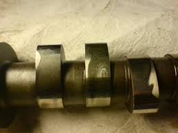
The shiny bits are where the cam lobe is touching the lifter. The base circle is shiny so we can tell this cam operated against a hydraulic lifter which stayed in contact with it all the time unlike a solid lifter cam which will have a tappet clearance. Then you get the distinctive half moon shiny bit up near the nose which matches where the cam lobe was touching in the first drawing. Most of the flank of the lobe never touches the lifter at all.
So what determines how far out this contact point moves? Clearly it can't move out beyond the edge of the lifter because then the lobe would miss the flat face of the lifter, dig into its edge and everything would break. I'll cover that in the next part. In the final part I'll look at the various parts of the cam lobe geometry, how they are specified and what effect each one has on engine performance.
You can see that the contact point is well away from the centreline of the cam lobe, out towards the edge of the lifter. If you imagine the cam continuing to rotate the contact point will move back to the dotted centreline as the cam nose reaches peak lift and also be there whenever the cam is on its base circle.
You can also see that because the lifter is circular, when the contact point is so far out towards the edge then not all of the cam lobe is actually touching the lifter. Most of it is sticking out into fresh air. Only a bit of one edge of the lobe is pushing against the lifter. Here's another nice pic of cam lobe wear patterns.
The shiny bits are where the cam lobe is touching the lifter. The base circle is shiny so we can tell this cam operated against a hydraulic lifter which stayed in contact with it all the time unlike a solid lifter cam which will have a tappet clearance. Then you get the distinctive half moon shiny bit up near the nose which matches where the cam lobe was touching in the first drawing. Most of the flank of the lobe never touches the lifter at all.
So what determines how far out this contact point moves? Clearly it can't move out beyond the edge of the lifter because then the lobe would miss the flat face of the lifter, dig into its edge and everything would break. I'll cover that in the next part. In the final part I'll look at the various parts of the cam lobe geometry, how they are specified and what effect each one has on engine performance.
Is it possible you could do some basic nomenclature? As was noted on a recent thread we've got people incorrectly calling cam covers rocker covers and cam boxes, I think for the novice, lesser experienced and um, younger people reading this it's difficult to understand which part is which, especially as pushrods are very uncommon now. Finger followers or rockers?
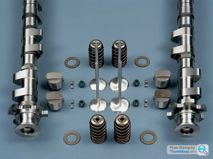
Hope you don't mind me posting these up (if I follow you correctly I don't think you've mentioned them), but they are OHC radiused buckets, Pic is of a BMW engine, although they are by no means new technology:

Are these used so you can have very aggressive cams, but less wear on some of the valvetrain components?
And these look very interesting: http://www.xrallyparts.com/PBProduct.asp?ItmID=807...
Then maybe we can talk about desmodromic....
Hope you don't mind me posting these up (if I follow you correctly I don't think you've mentioned them), but they are OHC radiused buckets, Pic is of a BMW engine, although they are by no means new technology:
Are these used so you can have very aggressive cams, but less wear on some of the valvetrain components?
And these look very interesting: http://www.xrallyparts.com/PBProduct.asp?ItmID=807...
Then maybe we can talk about desmodromic....
I can understand Rocker Cover being incorrect for an OHC engine if it has no rocker arms, but why is cambox incorrect, many folk refer to the cover as a cambox, esp on plant, aero and motorcycle engines.
Attached a link to a pic of a Napier cambox.
http://commons.wikimedia.org/wiki/File:Napier_Lion...
Peter
Attached a link to a pic of a Napier cambox.
http://commons.wikimedia.org/wiki/File:Napier_Lion...
Peter
Part 3.
Imagine a seesaw set absolutely horizontal and you're looking at it from the side. Now rotate the seesaw one degree clockwise. How far does any part of the beam move vertically? If the far end of one side moves 4 inches vertically then half way along the beam it will move 2 inches and a quarter of the way from the pivot only 1 inch. Imagine we want to position something contacting the beam so it moves a given distance for every 1 degree of beam rotation. The more we want the thing to move the further out we have to place it. This is how cam lobes work. They move the follower a certain distance per degree of cam rotation and the bigger we want this movement to be the further from the centreline the contact point moves out.
This movement of the follower per degree of cam rotation is called the cam velocity. It's measured in thou of follower lift per degree of cam rotation. The higher the value of this lift the further out the contact point becomes and the bigger the follower needs to be.
The equation that governs this is as follows.
From the cam centreline the Contact Point = lift per degree of cam rotation x 180/pi (57.3).
So if we want the cam to reach a maximum velocity of 10 thou per degree of rotation the cam follower must have a radius of at least 10 x 57.3 = 573 thou = 0.573" = 14.5 mm, or a diameter of 29 mm.
So the follower diameter places a direct limit on how fast the follower can open. This is independent of cam lobe size and purely a function of the opening rate.
If the follower diameter is small then the system needs a rocker to multiply the movement so the valve itself opens at a reasonable rate. This is how pushrod engines are designed. If the follower is large enough then all the valve movement can be created directly from the cam lobe i.e OHC engines.
In the next part I'll look at the four main areas of a cam lobe profile.
PeterBurgess said:
I can understand Rocker Cover being incorrect for an OHC engine if it has no rocker arms, but why is cambox incorrect, many folk refer to the cover as a cambox, esp on plant, aero and motorcycle engines.
Attached a link to a pic of a Napier cambox.
http://commons.wikimedia.org/wiki/File:Napier_Lion...
Peter
Why do you want to spoil this thread with a petty argument? I used it as an example of how people can get mixed up with nomenclature, if you want to argue then post up in the relevant thread where it was contested.Attached a link to a pic of a Napier cambox.
http://commons.wikimedia.org/wiki/File:Napier_Lion...
Peter
ShiningWit said:
Why do you want to spoil this thread with a petty argument? I used it as an example of how people can get mixed up with nomenclature, if you want to argue then post up in the relevant thread where it was contested.
I'm afraid this is what trolls do. They try and create arguments and then sit back and take some sort of perverse pleasure in the ensuing mayhem.ShiningWit said:
Is it possible you could do some basic nomenclature? As was noted on a recent thread we've got people incorrectly calling cam covers rocker covers and cam boxes, I think for the novice, lesser experienced and um, younger people reading this it's difficult to understand which part is which, especially as pushrods are very uncommon now. Finger followers or rockers?
Hope you don't mind me posting these up (if I follow you correctly I don't think you've mentioned them), but they are OHC radiused buckets, Pic is of a BMW engine, although they are by no means new technology:
Are these used so you can have very aggressive cams, but less wear on some of the valvetrain components?
And these look very interesting: http://www.xrallyparts.com/PBProduct.asp?ItmID=807...
Then maybe we can talk about desmodromic....
Just just call it a valve cover, like you do over here.Hope you don't mind me posting these up (if I follow you correctly I don't think you've mentioned them), but they are OHC radiused buckets, Pic is of a BMW engine, although they are by no means new technology:
Are these used so you can have very aggressive cams, but less wear on some of the valvetrain components?
And these look very interesting: http://www.xrallyparts.com/PBProduct.asp?ItmID=807...
Then maybe we can talk about desmodromic....
Stan
PS - Also I do not not if any others could see this picture but I could not. Even when I went to Speed talk I had to Log In to see it.
Edited by Stan Weiss on Sunday 15th February 14:56
Pumaracing said:
Welcome Stan. 10 am over there so I'm guessing you've already had your Cornflakes and let the hound dogs out for a wee.
DaveNo Cornflakes for me and since I do not drink coffee anymore, I had some tea and it was 9 degrees out and the wind chill was -13. Not fit for man nor beast.
Stan
Stan Weiss said:
Dave
No Cornflakes for me and since I do not drink coffee anymore, I had some tea and it was 9 degrees out and the wind chill was -13. Not fit for man nor beast.
Stan
The oil in your truck will be like grease at that temperature. At least you can walk underneath it and change it to something thinner without ducking your head.No Cornflakes for me and since I do not drink coffee anymore, I had some tea and it was 9 degrees out and the wind chill was -13. Not fit for man nor beast.
Stan
Tea? We'll turn you into a civilised European yet

Is it possible you could do some basic nomenclature? As was noted on a recent thread we've got people incorrectly calling cam covers rocker covers and cam boxes,...as said by Shining Wit
Now then Mr Shining Wit, I was not making the thread petty you posted the above and I replied to that, do you have a problem with that or didnt you post that? I thought folk were entitled to post on matters relevanton a thread and as Mr ShiningWit first mentioned the box etc I was merely responding.
Peter
Pumaracing said:
The oil in your truck will be like grease at that temperature. At least you can walk underneath it and change it to something thinner without ducking your head.
Tea? We'll turn you into a civilised European yet
Dave,Tea? We'll turn you into a civilised European yet
While it was not that cold yesterday, I did start and drive my all wheel drive / DOHC 4 cylinder without any trouble. I am sure that the 5W20 weight oil was still very thin today even in that cold.
One would need to be no more than 14 inches / 35.56 cm to walk under it that is unless the earth opens up for you. <g>
Stan
PS- have you as a civilized European got indoor running water on the farm?
Gassing Station | Engines & Drivetrain | Top of Page | What's New | My Stuff