The geometry of cam / follower systems
Discussion


Stan Weiss said:
PS- have you as a civilized European got indoor running water on the farm?
We even have the option of hot from some taps. 
Mind you, it didn't quite pass the local authority water quality test when I bought the house (too much nitrate) and there were a couple of dead mice floating in the borehole last time I had the cover off, but it tastes ok. Especially if diluted with enough whisky.
ShiningWit said:
Is it possible you could do some basic nomenclature? As was noted on a recent thread we've got people incorrectly calling cam covers rocker covers and cam boxes, I think for the novice, lesser experienced and um, younger people reading this it's difficult to understand which part is which, especially as pushrods are very uncommon now. Finger followers or rockers?
A rocker acts between a pushrod and a valve tip with the pivot in the middle. The cam in that situation acts on the circular follower underneath the pushrod. A finger follower acts between a pivot point at one end, the valve stem at the other and the cam lobe bearing directly on the finger as in the Ford Pinto OHC engine. Some bike engines also use this design.ShiningWit said:
Hope you don't mind me posting these up (if I follow you correctly I don't think you've mentioned them), but they are OHC radiused buckets, Pic is of a BMW engine, although they are by no means new technology:
This is essentially the pad from a Ford Pinto type finger follower designed into a sliding bucket which is pinned so it can't rotate. The advantage is that the cam lobe always has its full width to operate against the follower on. As the posts above have shown, with a circular rotating follower the lobe is only touching the follower on a very small area at maximum velocity when the contact point is out at the edge and this is where the lobe generally starts to fail if contact pressures get too high.Here is an actual measurement plot of a solid lifter flat tappet cam from my database of cams I've measured over the years. I've shown just the opening side of the curve, the closing side is more or less symmetrical, and split the curve into 4 sections, A to D. 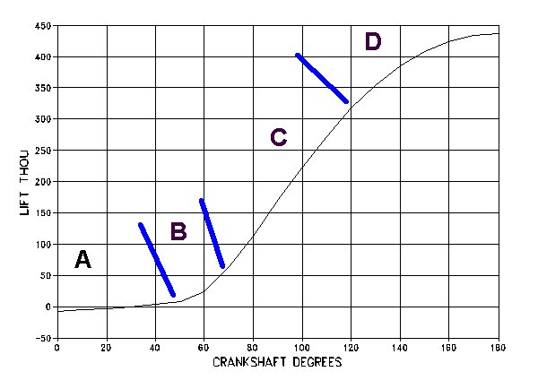
A - Opening (Clearance) Ramp
This is where the valve clearance is taken up. This has to be done very slowly so as not to smash the lobe into the cam follower. Normal opening rates are about 1 thou of lift for every 3 crankshaft degrees. To allow for wear and poor maintenance the ramp has to extend for a few thou above whatever the specified valve clearance is and this poses some problems for engine performance. Because the ramp is so slow any surplus over and above the specified valve clearance can use up a lot of valuable crankshaft degrees of duration which could be better used for opening the valve fast and reaching a higher lift. I've drawn the zero line on the Y axis at the specified 8 thou clearance but you can see the ramp extends beyond this for nearly another 20 degrees of crank rotation.
Hydraulic lifter cams don't need this long slow clearance ramp as the follower is always in contact with the lobe.
B - Acceleration Phase
Once the lobe and follower are in contact the lift can start accelerating fast. The forces produced are very high though and are limited by the materials of the lobe and lifter and the strength of the oil film between them. There's a certain amount of wiggle room for the cam designer in terms of acceleration rate versus wear and cam life but this part of the profile doesn't take up many crankshaft degrees anyway and is best not pushed too far.
C - Constant Velocity Phase
The lift rate has now reached the limit dictated by the follower diameter and nothing can be done to increase this.
D - Deceleration Phase
The rate at which the lobe velocity can slow back to zero is limited by the valve spring force which is all that is now keeping the valve and lifter against the lobe. This phase can be shortened if the valve spring rate is increased but that has adverse effects on wear and parasitic bhp losses.
In the final part I'll look at how these four phases of the cam profile can be varied for race cams versus stock road ones.
Dave,
Since I put almost 200K miles on it I have to bring up my Suzuki 1.5l SOHC Hemi which had rockers with a pad on one that ran against the cam.
The graphs show the difference between the lifter and the valve for both lift and velocity. This setup uses a 1.65:1 ratio rocker arm and a 0.021" valve lash.
Stan
Pumaracing said:
Ok you're drunk as a skunk eh? Posting nonsense for me. Get a grip man.
Dave,I am really sorry that you get confused so easily.
Let me do this in steps.
You A rocker acts between a pushrod and a valve tip with the pivot in the middle.
Me I have to bring up my Suzuki 1.5l SOHC Hemi which had rockers with a pad on one (should have had the word "end" here) that ran against the cam.
You Here is an actual measurement plot of a solid lifter flat tappet cam from my database of cams I've measured over the years. I've shown just the opening side of the curve, the closing side is more or less symmetrical, and split the curve into 4 sections, A to D.
Me The graphs show the difference between the lifter and the valve for both lift and velocity. This setup uses a 1.65:1 ratio rocker arm and a 0.021" valve lash.
You Mind you, it didn't quite pass the local authority water quality test when I bought the house (too much nitrate) and there were a couple of dead mice floating in the borehole last time I had the cover off, but it tastes ok. Especially if diluted with enough whisky.
You Ok you're drunk as a skunk eh? Posting nonsense for me. Get a grip man.
Me I think it is clear which one of us has had enough whiskey. Specially since I do not drink whiskey. Just a glass of wine now and then with dinner.
Stan
Edited by Stan Weiss on Monday 16th February 19:03
Stan Weiss said:
You Mind you, it didn't quite pass the local authority water quality test when I bought the house (too much nitrate) and there were a couple of dead mice floating in the borehole last time I had the cover off, but it tastes ok. Especially if diluted with enough whisky.
Stan
Stan
Edited by Stan Weiss on Monday 16th February 19:03
 Made me laugh
Stan Weiss said:
Dave,
Sorry for the confusion. I do not have an cam data from the Suzuki. That data is from a SBF v8.
Do you have an cam data files that you would like to share?
Stan
What sort of stuff are you interested in? I've got std and various performance profiles for Ford CVH, Peugeot 205, most of the Crane Rover V8 profiles (270, 224,234,248,256,266), MGB race cam and a bunch of oddball stuff including 5 valve per cylinder Audi V6 and the Kohler lawnmower engine I helped my apprentice turn into a kart race engine for his degree thesis.Sorry for the confusion. I do not have an cam data from the Suzuki. That data is from a SBF v8.
Do you have an cam data files that you would like to share?
Stan
Rats
Just wrote you a nice reply on why inverted bucket followers are certainly not flat and why you get scoring on followers in circles. Its all down to Hertzian contact loads and deformation and needing to maintain a finite contact patch and keeping that contact patch lubricated and separated by fractions of a micron...
...sadly I must have not hit the right button and deleted the lot...
Anyway, if any of you guys have a specific valvetrain issue the msg me and I may be able to help.
Bobley said:
Rats
Just wrote you a nice reply on why inverted bucket followers are certainly not flat and why you get scoring on followers in circles. Its all down to Hertzian contact loads and deformation and needing to maintain a finite contact patch and keeping that contact patch lubricated and separated by fractions of a micron...
...sadly I must have not hit the right button and deleted the lot...
Anyway, if any of you guys have a specific valvetrain issue the msg me and I may be able to help.
Dam i hate it when i do that^^^ (mind you, most of my posts are rubbish, so not a lot is lost! )Just wrote you a nice reply on why inverted bucket followers are certainly not flat and why you get scoring on followers in circles. Its all down to Hertzian contact loads and deformation and needing to maintain a finite contact patch and keeping that contact patch lubricated and separated by fractions of a micron...
...sadly I must have not hit the right button and deleted the lot...
Anyway, if any of you guys have a specific valvetrain issue the msg me and I may be able to help.
Pumaracing said:
What sort of stuff are you interested in? I've got std and various performance profiles for Ford CVH, Peugeot 205, most of the Crane Rover V8 profiles (270, 224,234,248,256,266), MGB race cam and a bunch of oddball stuff including 5 valve per cylinder Audi V6 and the Kohler lawnmower engine I helped my apprentice turn into a kart race engine for his degree thesis.
Dave,I would like whatever data you are willing to share. I am not sure yet what I will do with it other than personal use (Maybe add another table to my web site). I have a few of tables on my web site now.
Cylinder Heads Flow Data web page - http://users.erols.com/srweiss/tablehdc.htm
Electronic Fuel Injector (EFI) Flow Data Table web page - http://users.erols.com/srweiss/tableifc.htm
Engine, Bore, Stroke, Rod Length, Ratio Table - http://users.erols.com/srweiss/tablersn.htm
Transmission Gear Ratio Chart - http://users.erols.com/srweiss/transc.htm
If anyone has an information for any of these Tables that they would like to share / have added to these Tables please email it to me.
Stan
srweiss@erols.com
The Ford Pinto flow figures on your site have some problems. You've got two lines from me marked as "accuracy ???" which I don't recognise. Those need taking out. The other two (stock carb head and stock injection head) look ok and the valve size is 42mm.
The valve size on the CNC ported Pinto heads can't be 1.179" Maybe 1.79".
Here's one of my ported Pinto heads already converted to 28" for you. Inlet valve size 45.6mm
100 - 60
200 - 117
300 - 154
400 - 181
500 - 200
I don't really want any of my cam data on the site. The profiles are someone's intellectual property anyway and probably best not shared.
This might be of some interest to this discussion.
Stan
Solid Cam With "Forgiving" Lash Ramp Design?
http://speedtalk.com/forum/viewtopic.php?f=1&t...
Stan
Solid Cam With "Forgiving" Lash Ramp Design?
http://speedtalk.com/forum/viewtopic.php?f=1&t...
Stan Weiss said:
This might be of some interest to this discussion.
Stan
Solid Cam With "Forgiving" Lash Ramp Design?
http://speedtalk.com/forum/viewtopic.php?f=1&t...
Interesting.Stan
Solid Cam With "Forgiving" Lash Ramp Design?
http://speedtalk.com/forum/viewtopic.php?f=1&t...
A recent thing...at least as far as LS's are concerned and something I'm going to try myself.
Cam Motion are offering solid roller cams in what they call a low lash setup.
Basically it uses roller lifters and for an alloy block engine they say to basically adjust with zero lash. When the engine is warm it should then end up around 10thou at the valve/rocker. They even said to adjust with a slight pre-load when cold.
Obviously this is specifically because it's still retaining a roller lifter as opposed to a flat tappet lifter.
Pumaracing said:
What sort of stuff are you interested in? I've got std and various performance profiles for Ford CVH, Peugeot 205, most of the Crane Rover V8 profiles (270, 224,234,248,256,266), MGB race cam and a bunch of oddball stuff including 5 valve per cylinder Audi V6 and the Kohler lawnmower engine I helped my apprentice turn into a kart race engine for his degree thesis.
Any chance of posting up the Rover V8 crane 256.Gassing Station | Engines & Drivetrain | Top of Page | What's New | My Stuff