Calling Max_Torque - manifolds and turbos question
Discussion


Non expert opinion thinking out loud...
It would seem that there is a compromise to be had between the desire to spool quickly and the advantages of having tuned lengths employing Helmholtz principles.
Given an equal sized turbo, desire to spool quickly is satisfied by having the shortest length possible, hence the OEMs use cast log manifolds in the main as they can be packaged as close to the exhaust ports as possible.
Tuned lengths utilising the Helmholtz effect (reflected pressure waves) which aid cylinder filling will require the desired effective operating rpm to be identified. Unfortunately the length chosen will be effective over a narrow rpm range, possibly several narrow ranges dependant on whether the length is tuned to one or more harmonics. If more than one harmonic, the lengths will tend to be long due to the operating rpm range of the engine. The 1st harmonic being the strongest, but requiring significant length. Also as the pre turbine exhaust pressure increases the density of the gas increases, changing the speed of sound and therefor the rpm where the Helmholtz will be effective. Not only will pressure changes change the Helmholtz frequency, the temperature will also change the frequency, again changing the rpm range where the Helmholtz effective.
Added to where the positive effects of utilising Helmholtz effect, there is also a negative effect where the reflected pressure waves have a negative effect on cylinder filling.
All this leads to peaks and troughs of Helmholtz effect influenced not only be engine speed but also temp and pressure leading to peaks and troughs in the torque curve which would need to be ironed out with boost control strategy.
My guess is there is a s t load of maths to work out where the effects will occur and that will be based on assumptions of EGT and pre-turbine pressure, which of course you don't know right now as the engine hasn't run.
My advice would be equal lengths as short as possible, negating the need to work out the ideal length for all the parameters and the need for a complex boost control strategy utilising the same parameters to smooth the torque curve.
It would seem that there is a compromise to be had between the desire to spool quickly and the advantages of having tuned lengths employing Helmholtz principles.
Given an equal sized turbo, desire to spool quickly is satisfied by having the shortest length possible, hence the OEMs use cast log manifolds in the main as they can be packaged as close to the exhaust ports as possible.
Tuned lengths utilising the Helmholtz effect (reflected pressure waves) which aid cylinder filling will require the desired effective operating rpm to be identified. Unfortunately the length chosen will be effective over a narrow rpm range, possibly several narrow ranges dependant on whether the length is tuned to one or more harmonics. If more than one harmonic, the lengths will tend to be long due to the operating rpm range of the engine. The 1st harmonic being the strongest, but requiring significant length. Also as the pre turbine exhaust pressure increases the density of the gas increases, changing the speed of sound and therefor the rpm where the Helmholtz will be effective. Not only will pressure changes change the Helmholtz frequency, the temperature will also change the frequency, again changing the rpm range where the Helmholtz effective.
Added to where the positive effects of utilising Helmholtz effect, there is also a negative effect where the reflected pressure waves have a negative effect on cylinder filling.
All this leads to peaks and troughs of Helmholtz effect influenced not only be engine speed but also temp and pressure leading to peaks and troughs in the torque curve which would need to be ironed out with boost control strategy.
My guess is there is a s
t load of maths to work out where the effects will occur and that will be based on assumptions of EGT and pre-turbine pressure, which of course you don't know right now as the engine hasn't run. My advice would be equal lengths as short as possible, negating the need to work out the ideal length for all the parameters and the need for a complex boost control strategy utilising the same parameters to smooth the torque curve.
Sorry for the tardy appearance on the this thread!
But, the good news, is that given a couple of caveats, exhaust design on a modern turbo engine "doesn't really matter" (by which i mean, it won't make THAT much difference to the end result).
Firstly, those caveats:
1) You are not aiming to make the absolutely highest possible output (ie, you are not designing a F1 engine)
2) You don't care about exhaust emissions (you don't have to meet EU6 tailpipe limits etc)
3) You are not air (inlet restrictor) or fuel (peak fuel mass) limited
So, what do i mean by "won't make THAT much difference"?
Well, with the assumption that your design isn't GROSSLY incorrect, for example you have't used 10mm dia tubes that completely strangle the engine!) changes in manifold volumetric efficiency from exhaust manifold design on a turbo engine are worth, typically, a maximum of 5%. That is the same airflow difference you get from just 5kPa of extra boost pressure (~0.7 psi for people working in old money!)
As exhaust manifold enthalpy changes so massively with different operating conditions (changes in exhaust density due to pressure and temperature variations) specific frequency tuning is largely superfluous, especially on a heavily (eg >1bar boost) turbo charged engine where turbine efficiency factors outweigh manifold volumetric factors (engine voleff != manifold voleff).
As a fundamental design constraint, a turbine is a HEAT engine, rather than a pressure engine (ok, it's both, it's an Enthalpy engine really, but heat, ie temperature dominates because it is so variable). Modern OE turbo engines have tended towards ultra low volume, low thermal inertia exhaustlines (eh "hotside" engines with turbo's in the engine V) to maximise heat recovery, increasing response and energy recovery at the expense of ultimate performance typically at around 125bhp/litre, despite up to 200bhp/litre being relatively easily available on pump fuels these days)
Your big win is the use of inconel. This material has a poor thermal transfer co-efficient (keeps heat in!) and a low thermal inertia because you use it in thin tube form (not thick cast style manifolds). This will allow you to maintain an efficiency heat recovery despite a larger exhaust manifold volume.
The likely driving factors for a practicable design are as follows:
1) Exhaust port shape and area at the exhaust manifold flange - you want a SIGNIFICANT anti-reversal flange, which means your exh manifold flange needs to be at least 3mm bigger all round than the port exit. This will drive you towards a larger overall manifold tube diameter. However, depending on the CSA you end up with, you may want to cone down to a smaller main tube dia to maintain reduce manifold volume. Typically, you'd come back down, using a 3deg taper to the same dia as the exh port at head exit.
2) The turbine entry type and size of your turbocharger - again, this really drives the design. Assuming you have sized the turbine and scroll correctly, your manifold needs to mate cleanly to your turbine, and if it's a dual scroll etc, needs to be suitably split to maximise pressure pulse energy recovery.
3) Overall length is a massive compromise, between low rpm response (short) and max power (long). Take a look as some examples:
a) 1980's F1 turbos 1000bhp/litre, laggy as F**K:
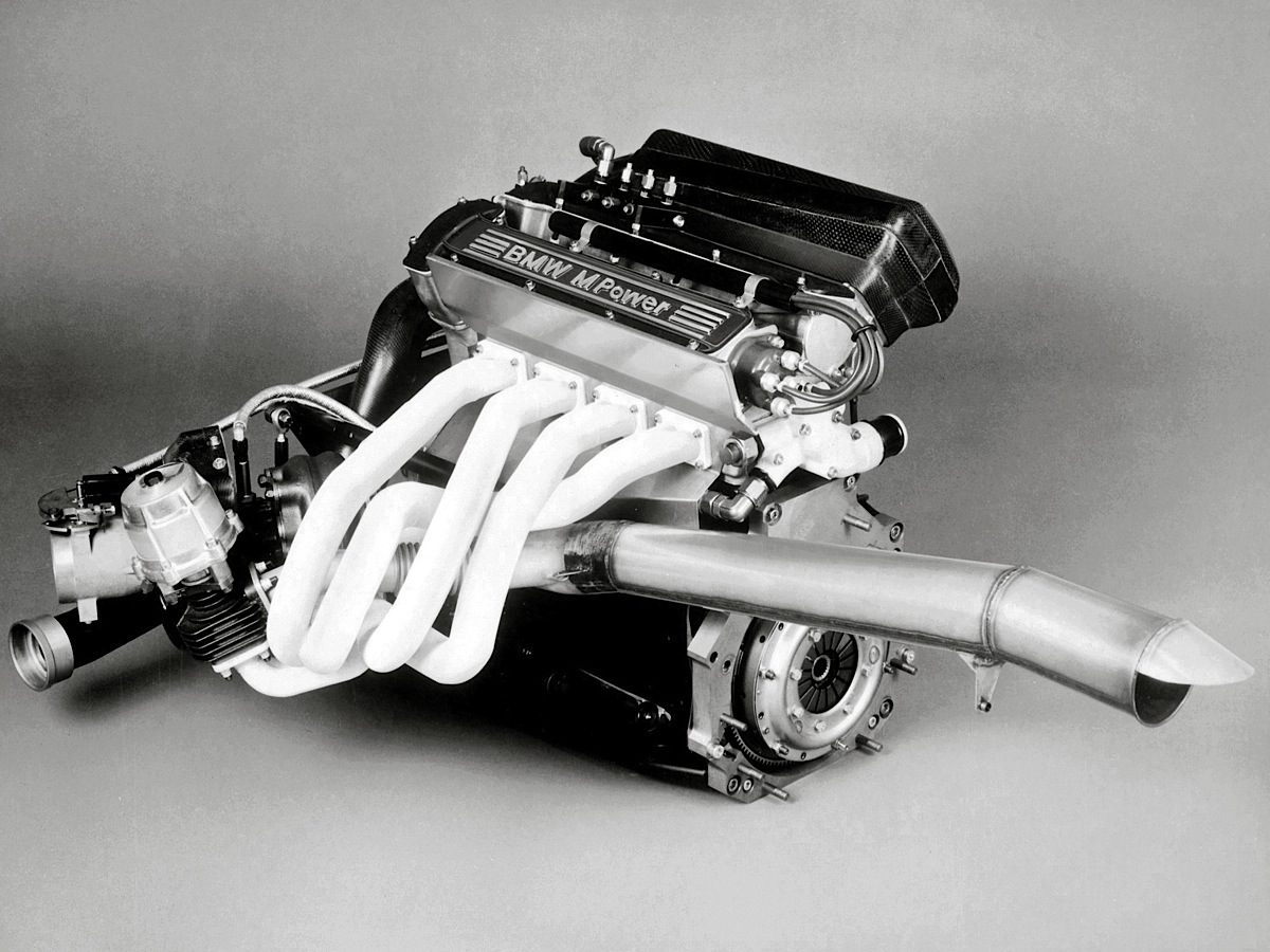
The heat loss and manifold volume to engine cc ratio are skewed massively to lowest possible losses at high exhaust mass flow conditions - no practical pulse pressure recovery by the (also huge) single scroll turbine
b) BMW "hotside" turbo V8 passenger car engine:
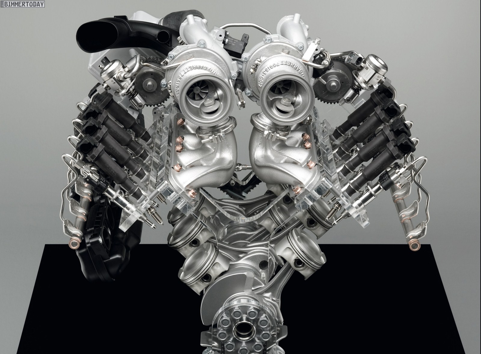
Tiny, short well insulated manifolds
b) A modern V6 turbo LeMans engine, the "compromise" engine (powerfull, but with high efficiency due to fuel/air limitation
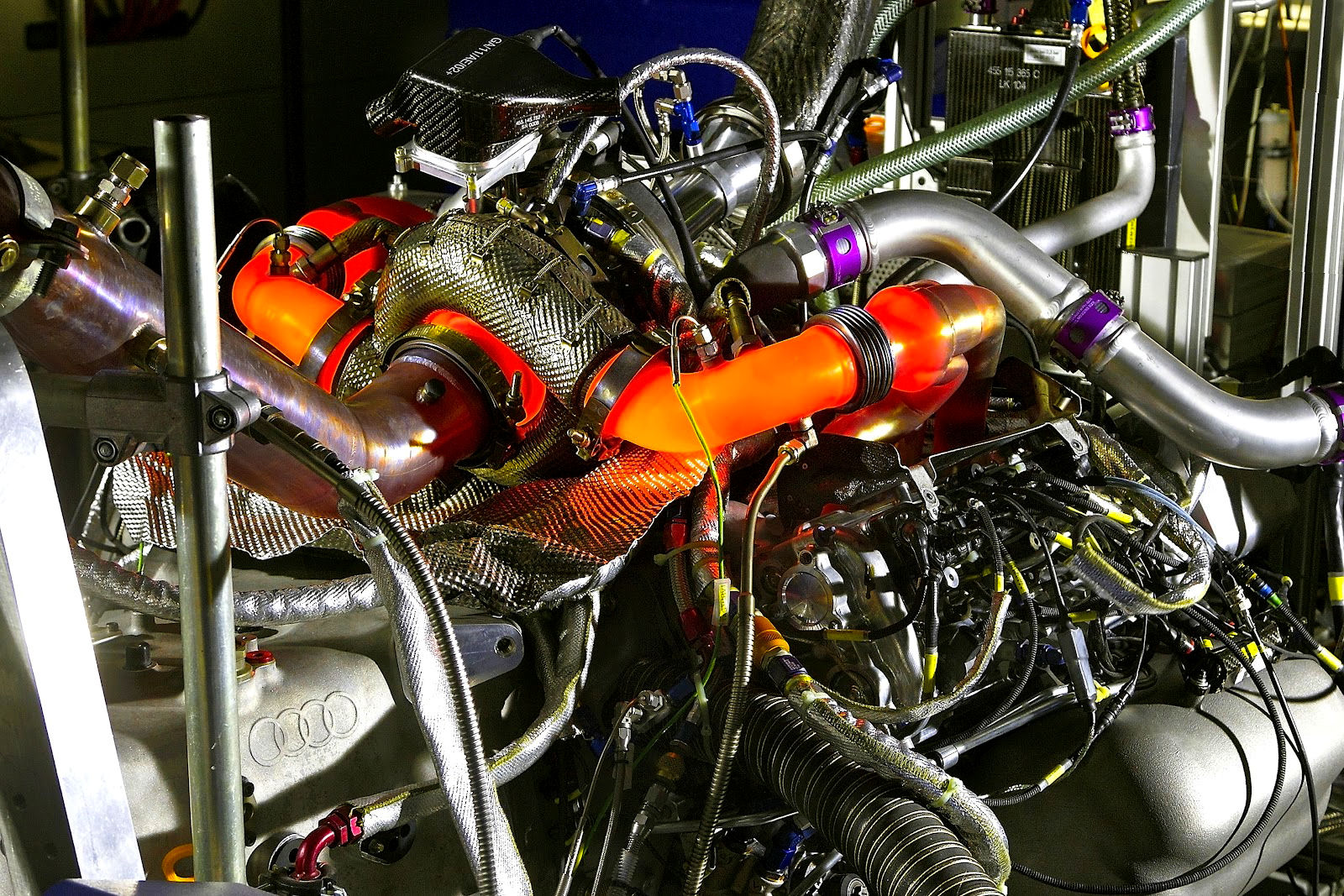
Large diameter, but relatively short and well insulated where possible (twin skinned etc)
As the OP's vehicle is lightweight and mid engined, i'd suggest erring for a engine characteristic of control and response, and not power / lag! In this respect, several modern techniques bring huge benefits above those directly coming from exhaust manifold design, namely:
1) Electronic throttle, running in slow "airpath" control - the throttle controls air mass, not engine torque
2) Pre-throttle boost pressure control with electronic wastegate actuation - ideally with turbo shaft speed feedback - control the wastegate to control instantaneous turbo work, not to control engine air mass
3) Dual Variable cam timing - make your exhaust cam suit your engine operating condition, and not the other way round (probably don't have this on your engine, so you will need to optimise exhaust cam duration an timing, which WILL therefore be a compromise)
4) Fast path torque control during dynamic conditions only - cut or retard ignition angle / fueling rather than adjust throttle position during things like gear shift or TSC intervention, to maintain turbo work at a fixed level to mitigate transient boosting lag
5) Deliberate optimisation of ignition angle to maximise exhaust enthalpy in off boost zones - retard ignition in those zones where the driver asks for WOT, but the turbo hasn't delivered yet - this is a compromise between max flywheel torque when N/A and reducing lag.
Without a fully validated and corelated model of your engine, you are never really going to be able to optimse things to the nth degree. IME, the best path is to get the vehicle running with a good (say an 80% design) but 1st attempt manifold ASAP, then measure as much data as possible (objective and subjective) and use a proper data-driven engineering process to design a better second attempt. This approach is likely to result in a better outcome in a shorter time that trying to aim for a 100% manifold on the first attempt with so many unknown variables and targets! If you can afford it, i'd suggest that the measurement of turbine shaft speed is critical to the success of engine / turbo optimisation. This has become a lot cheaper to do these days than it used to be.
(most armature racers and hobbists are not data-driven. They often claim to want to make the best possible thing, but completely fail to actually measure anything, and hence can't establish the basic operating conditions for that thing, meaning further optimisation is just guessing......)
The basic steps you will need to have done, even if these are estimates currently are:
1) plot a WOT torque curve vs engine rpm
2) Estimate BSAC and turn that torque curve into an air flow curve
3) plot the turbo charger compressor WOT operating line and power requirement, calc inlet velocites and required ENG/MAN vol eff
4) Estimate exhaust mass flow (take a sensible stab at likely AFR, say 12.5:1 at low rpm, dropping to 11:1 at peak power rpm)
5) Take a stab at calculating average exhaust velocity, work backwards from compressor power to turbine power, check where you sit on the steady state turbine map
I'd suggest installing the following instrumentation on the engine during build and development
Vital:
1) Pre turbine EGT (usually in exh manifold, 50mm upstream of turbine flange, but make sure it's at a location where the exhaust from all ports is seen)
2) Pre turbine pressure (again 50mm upstream of turbine flange, use at least 300mm of 6mm stainless steel pipe to reduce temp before connecting to pressure sensor
3) Pre and post compressor temperature
4) Post compressor pressure (i'm assuming post throttle pressure and temperature is recorded by your EMS system)
5) Exhaust lambda
Nice to have:
6) Turbo shaft speed
7) post turbine pressure and temperature
8) wastegate capsule pressure (if pneumatically controlled, otherwise w/g position from elec actuator)
Are you engine dyno mapping or chassis dyno mapping btw? (if you really want decent performance, then engine dyno with controlled boundary conditions (ie charge temp control etc) is vital, and you'll want to carry out boundary condition sensitivity sweeps etc to understand the factorial interactions.)
That's probably enough to be going on with ;-)
But, the good news, is that given a couple of caveats, exhaust design on a modern turbo engine "doesn't really matter" (by which i mean, it won't make THAT much difference to the end result).
Firstly, those caveats:
1) You are not aiming to make the absolutely highest possible output (ie, you are not designing a F1 engine)
2) You don't care about exhaust emissions (you don't have to meet EU6 tailpipe limits etc)
3) You are not air (inlet restrictor) or fuel (peak fuel mass) limited
So, what do i mean by "won't make THAT much difference"?
Well, with the assumption that your design isn't GROSSLY incorrect, for example you have't used 10mm dia tubes that completely strangle the engine!) changes in manifold volumetric efficiency from exhaust manifold design on a turbo engine are worth, typically, a maximum of 5%. That is the same airflow difference you get from just 5kPa of extra boost pressure (~0.7 psi for people working in old money!)
As exhaust manifold enthalpy changes so massively with different operating conditions (changes in exhaust density due to pressure and temperature variations) specific frequency tuning is largely superfluous, especially on a heavily (eg >1bar boost) turbo charged engine where turbine efficiency factors outweigh manifold volumetric factors (engine voleff != manifold voleff).
As a fundamental design constraint, a turbine is a HEAT engine, rather than a pressure engine (ok, it's both, it's an Enthalpy engine really, but heat, ie temperature dominates because it is so variable). Modern OE turbo engines have tended towards ultra low volume, low thermal inertia exhaustlines (eh "hotside" engines with turbo's in the engine V) to maximise heat recovery, increasing response and energy recovery at the expense of ultimate performance typically at around 125bhp/litre, despite up to 200bhp/litre being relatively easily available on pump fuels these days)
Your big win is the use of inconel. This material has a poor thermal transfer co-efficient (keeps heat in!) and a low thermal inertia because you use it in thin tube form (not thick cast style manifolds). This will allow you to maintain an efficiency heat recovery despite a larger exhaust manifold volume.
The likely driving factors for a practicable design are as follows:
1) Exhaust port shape and area at the exhaust manifold flange - you want a SIGNIFICANT anti-reversal flange, which means your exh manifold flange needs to be at least 3mm bigger all round than the port exit. This will drive you towards a larger overall manifold tube diameter. However, depending on the CSA you end up with, you may want to cone down to a smaller main tube dia to maintain reduce manifold volume. Typically, you'd come back down, using a 3deg taper to the same dia as the exh port at head exit.
2) The turbine entry type and size of your turbocharger - again, this really drives the design. Assuming you have sized the turbine and scroll correctly, your manifold needs to mate cleanly to your turbine, and if it's a dual scroll etc, needs to be suitably split to maximise pressure pulse energy recovery.
3) Overall length is a massive compromise, between low rpm response (short) and max power (long). Take a look as some examples:
a) 1980's F1 turbos 1000bhp/litre, laggy as F**K:
The heat loss and manifold volume to engine cc ratio are skewed massively to lowest possible losses at high exhaust mass flow conditions - no practical pulse pressure recovery by the (also huge) single scroll turbine
b) BMW "hotside" turbo V8 passenger car engine:
Tiny, short well insulated manifolds
b) A modern V6 turbo LeMans engine, the "compromise" engine (powerfull, but with high efficiency due to fuel/air limitation
Large diameter, but relatively short and well insulated where possible (twin skinned etc)
As the OP's vehicle is lightweight and mid engined, i'd suggest erring for a engine characteristic of control and response, and not power / lag! In this respect, several modern techniques bring huge benefits above those directly coming from exhaust manifold design, namely:
1) Electronic throttle, running in slow "airpath" control - the throttle controls air mass, not engine torque
2) Pre-throttle boost pressure control with electronic wastegate actuation - ideally with turbo shaft speed feedback - control the wastegate to control instantaneous turbo work, not to control engine air mass
3) Dual Variable cam timing - make your exhaust cam suit your engine operating condition, and not the other way round (probably don't have this on your engine, so you will need to optimise exhaust cam duration an timing, which WILL therefore be a compromise)
4) Fast path torque control during dynamic conditions only - cut or retard ignition angle / fueling rather than adjust throttle position during things like gear shift or TSC intervention, to maintain turbo work at a fixed level to mitigate transient boosting lag
5) Deliberate optimisation of ignition angle to maximise exhaust enthalpy in off boost zones - retard ignition in those zones where the driver asks for WOT, but the turbo hasn't delivered yet - this is a compromise between max flywheel torque when N/A and reducing lag.
Without a fully validated and corelated model of your engine, you are never really going to be able to optimse things to the nth degree. IME, the best path is to get the vehicle running with a good (say an 80% design) but 1st attempt manifold ASAP, then measure as much data as possible (objective and subjective) and use a proper data-driven engineering process to design a better second attempt. This approach is likely to result in a better outcome in a shorter time that trying to aim for a 100% manifold on the first attempt with so many unknown variables and targets! If you can afford it, i'd suggest that the measurement of turbine shaft speed is critical to the success of engine / turbo optimisation. This has become a lot cheaper to do these days than it used to be.
(most armature racers and hobbists are not data-driven. They often claim to want to make the best possible thing, but completely fail to actually measure anything, and hence can't establish the basic operating conditions for that thing, meaning further optimisation is just guessing......)
The basic steps you will need to have done, even if these are estimates currently are:
1) plot a WOT torque curve vs engine rpm
2) Estimate BSAC and turn that torque curve into an air flow curve
3) plot the turbo charger compressor WOT operating line and power requirement, calc inlet velocites and required ENG/MAN vol eff
4) Estimate exhaust mass flow (take a sensible stab at likely AFR, say 12.5:1 at low rpm, dropping to 11:1 at peak power rpm)
5) Take a stab at calculating average exhaust velocity, work backwards from compressor power to turbine power, check where you sit on the steady state turbine map
I'd suggest installing the following instrumentation on the engine during build and development
Vital:
1) Pre turbine EGT (usually in exh manifold, 50mm upstream of turbine flange, but make sure it's at a location where the exhaust from all ports is seen)
2) Pre turbine pressure (again 50mm upstream of turbine flange, use at least 300mm of 6mm stainless steel pipe to reduce temp before connecting to pressure sensor
3) Pre and post compressor temperature
4) Post compressor pressure (i'm assuming post throttle pressure and temperature is recorded by your EMS system)
5) Exhaust lambda
Nice to have:
6) Turbo shaft speed
7) post turbine pressure and temperature
8) wastegate capsule pressure (if pneumatically controlled, otherwise w/g position from elec actuator)
Are you engine dyno mapping or chassis dyno mapping btw? (if you really want decent performance, then engine dyno with controlled boundary conditions (ie charge temp control etc) is vital, and you'll want to carry out boundary condition sensitivity sweeps etc to understand the factorial interactions.)
That's probably enough to be going on with ;-)
Steve_D said:
Max_Torque said:
.......That's probably enough to be going on with ;-)...
You think?Excellent work as always. Didn't understand a half of it but made a very good lunchtime read.
Thanks
Steve

Agree totally though it was, as every, a very interesting and informative read. Crazy how much stuff you need to think about.
(Steve pretty much said the same earlier in the thread).
chuntington101 said:
To translate I think max is saying just build it to be equal-ish length and not too big runners and not too long. the rest is stuff not related to the manifold!
Agree totally though it was, as every, a very interesting and informative read. Crazy how much stuff you need to think about.
(Steve pretty much said the same earlier in the thread).
Yup...but in English lol.Agree totally though it was, as every, a very interesting and informative read. Crazy how much stuff you need to think about.
(Steve pretty much said the same earlier in the thread).
Many thanks for th detailed and interesting reply
So, sorry, going back to length for my initial stab at it, a starting point if you will... and as you say probably only worth ~5% but regardless, I'm interested in the theory...
If I'm aiming for a compromise and if I take the lengths used by the NA builds for this engine that are known to work well (27" manifold primaries for example)... where should I start? The shortest possible is probably around 12" of equal length... I was aiming for around 24" inclusive of merge collector, does that sound around right for a first attempt?
I am aiming to log as much as possible, so far I have built into the design & will log:
1. Inlet manifold map sensor
2. Exhaust manifold map sensor (on coiled stainless pipe)
3. Pre turbine EGT sensor (single)
4. Post turbine Lambda
7. Compressor outlet air temp sensor
8. Inlet manifold air temp sensor
9. Inlet manifold air pressure sensor
So it sounds like I need to add an additional:
1. Pre compressor temp sensor (to log and understand compressor efficiency)
2. Post compressor pressure sensor
3. Wastegate pressure sensor (just a normal map sensor I'm assuming?)
Sadly my compressor cover does not have a boss for a compressor / shaft speed sensor like the new Borg Warner EFR turbos, so while I could have mine machined I'll probably not be able to log at this stage, similarly I don't think my wastegate has a position sensor option like some of the new breed... I could add post turbine pressure and temperature easily enough but I'm not sure I have any inputs left for logging / recording...
The manifold pipe size is just about the same as the exhaust port area, we can flare it at the manifold flange to create the anti reversion step and taper at 3 degrees back to the same area - thanks for this tip!!
I am using an electronic throttle so will hopefully be able to take into account your advice depending on what options / control my ECU allows.
I'm chassis logging, while I would dearly love to engine dyno it will add significant time to the project... and while I do want to make the best possible stab at it, I also would like to drive it at some point in the coming year
Thanks again... lots to think about!
Edited by sl0wlane on Sunday 4th December 10:18
I would be very surprised if 27" is an ideal tuned length for every single engine of that kind....for every single head/intake combination, every single camshaft choice and not even a mention of tube diameter, nor desired operating rpm range for each particular engine.
Therein lies the issue I've been repeating. It will not be optimal, there is no generic optimal and without thousands of hours dyno time and huge costs...you will never find optimal for your specific combo and operating range
You could go overboard logging some stuff and it sounds like your ecu has some limitations there ?
IMO if you really want to find turbo etc efficiency, turbo speed would be far more important than post compressor pressure etc
Really...if you have issues between post compressor and intake....you should have built a more efficient charge cooler/plumbing. Which would have been a major cost cutting exercise when you're worried so much about the exhaust manifold. Spending the money on areas like that and not being so concerned about the exhaust, would perhaps be better.
Given the space you seem to have, it would be incredibly difficult to build a bad exhaust manifold.
You could log post turbine pressure...but again, why would you build an exhaust that is restrictive in the first place to actually need to log this ? Unless perhaps there are huge noise restrictions you need to abide by.
If your logging options are limited, log important stuff, or use a better ecu that can log everything you want. Logging is always good if you have the abilities for it !
Even logging wastegate pressure...I assume you mean top port pressure here ? Unless you're going to be using this for boost control there probably isnt a huge point in that either ( again unless you have plenty of spare logging channels )
W/g position would probably be more useful long term, plenty of options for these around now.
And if you're intent on the "best" exhaust manifold, you'd likely be running 2 wastegates for a full twin scroll system...so now you have data for 2 gates to log, unless you Y the manifold to gate tubes into a single gate.
My 10 pence: (well, probably 20 pence worth tbh ;-)
You want to log the necessary data to be able to accurately calculate turbocharger work and efficiency,and critically, see where you are actually running on your current compressor / turbine maps. High boost turbo engines are ALL ABOUT THE TURBO, as every % point better compressor efficiency equals less intercooler work, less turbine work (less EBP!).
As a minimum, i'd want to see compressor operating lines, so you need pre/ post temp and pressure, however, assuming you are picking up cold air (not hot enigne bay air) with a decent, low rtestriction inlet, you can probably just use ambient conditions for the inlet. (remember to correct to static pressures).
In terms of exhaust manifold length, that really tricky. Firstly, unless you are planning on your engine reving to proper rpm (think 12K upwards) you won't be able to make use of the fundamental wave in the pulse tuning, because that will require an exhaust about 6 feet long down at just 7krppm. So you are into the harmonics, which of course only carry a small proportion of the energy of the fundamental wave, so there is less to gain. You then need to decide at what point you want maximum manifold volumetric efficiency? For a race engine, it's easy, it's peak power rpm. For a road engine, it's more difficult, because you may want to tune your exhaust to provide max manifold voleff BEFORE the turbo threshold, in order to make the maximum N/A torque to improve spool and driveability etc. In all cases, you will need to carry out an exhaust (and probably inlet too) timing swing experiment to find out for any given manifold what valve timing you need to leverage any extra exhaust pulse tuning. Easy to do on an engine dyno, more of a PITA to do (engine buried in car, non repeatable boundary conditions) on a chassis dyno. IME, if you're not using an engine dyno, you are probably, ie, around 10% to 15% off the optimum max output settings on average (of course, you might get lucky, and hit the right settings for everything first tie on the chassis dyno, might.........)
I'd suggest to come up with two exhaust manifold designs, that are reasonably interchangeable, a "Long one" and a "short one". if you can arrange to be able to swap between these manifolds without significant extra work (ie, try to maintain same turbo location, perhaps just clocked a bit, or similar, or make sure oil water lines long enough for both positions, use post turbo exhaust spacer etc) then you can realistically try both on a chassis dyno session!
In terms of primary lengths, without more info, it's all a guess. As i suggested before, you need to at least estimate a calculated full load line, using sensible numbers, and then you can attempt to set some primary lengths.
The fact he wants to make the exhaust from inconel, has ecu logging limitations etc....would suggest there is a fairly tight budget ( yes I know inconel isnt cheap )
SO I really doubt all that dyno/testing time is an option, and I doubt he's up for building two exhaust manifolds.
BUT....if he was able to have long straight sections on the manifold tubes, he could maybe run slip joints and create a short/long version that way ?
Although it would then mean totally altering turbo position and all relevent connections.
Of course...that doesnt cover which tube diameter might be best.
Bottom line is the same thing, there is no easy or cheap way to simulate what he wants, or even test what he seeks.
Just build one based on the thousands that are already out there doing the same thing that already work well. By far the cheapest and safest option.
stevieturbo said:
Bottom line is the same thing, there is no easy or cheap way to simulate what he wants, or even test what he seeks.
IME, a basic 1d iterative "simulation" in something like excel gets you 85 to 90% of the way there! And, when you have logged the actual parameters from the vehicle, you can then re-correlate your simulation, or at least change the values of things like exhaust length and see what effect they have.It's pretty simple really, if you want the "Best" engine, you're going to have to do the math. If you are happy for a decent but, un-spectacular performance then just guessing and following what others have done will work ;-)
Max_Torque said:
IME, a basic 1d iterative "simulation" in something like excel gets you 85 to 90% of the way there! And, when you have logged the actual parameters from the vehicle, you can then re-correlate your simulation, or at least change the values of things like exhaust length and see what effect they have.
It's pretty simple really, if you want the "Best" engine, you're going to have to do the math. If you are happy for a decent but, un-spectacular performance then just guessing and following what others have done will work ;-)
Yep...but logging everything means building and testing it all in the first place, which is back to the £££ factor.It's pretty simple really, if you want the "Best" engine, you're going to have to do the math. If you are happy for a decent but, un-spectacular performance then just guessing and following what others have done will work ;-)
Presumably he wants to build once.
And he's stated he's only after around 500hp....certainly nothing difficult to achieve.
stevieturbo said:
I would be very surprised if 27" is an ideal tuned length for every single engine of that kind....for every single head/intake combination, every single camshaft choice and not even a mention of tube diameter, nor desired operating rpm range for each particular engine.
Absolutely, this length is often used on the high revving ~300bhp 2.2NA builds - I have no idea on the camshaft spec of those, but you are correct, on reflection this will be nothing like my requirement... still, I am looking for a starting point!stevieturbo said:
You could go overboard logging some stuff and it sounds like your ecu has some limitations there ?
The ECU has:4 inductive or Hall effect engine speed and synchronization sensor inputs
4 Hall effect wheel speed sensors
3 spare Hall effect / digital switch inputs
2 knock sensor inputs
8 spare analogue sensor inputs via CAN
1 direct NTK UEGO lambda sensor input
20 analogue 0..5 Volts external sensor inputs (can also be used as switch inputs)
1 built-in barometric air pressure sensor
I need to add up everything I already have, perhaps I do have enough inputs.
stevieturbo said:
Really...if you have issues between post compressor and intake....you should have built a more efficient charge cooler/plumbing. Which would have been a major cost cutting exercise when you're worried so much about the exhaust manifold. Spending the money on areas like that and not being so concerned about the exhaust, would perhaps be better.
I haven't built the inter-cooler yet ?!?stevieturbo said:
Given the space you seem to have, it would be incredibly difficult to build a bad exhaust manifold.
You could log post turbine pressure...but again, why would you build an exhaust that is restrictive in the first place to actually need to log this ? Unless perhaps there are huge noise restrictions you need to abide by.
I have requested a 3.5" down-pipe from the turbine exit, through to the back box - should be very little restriction. The waste-gate will be entirely divorced and have its own tail pipe.You could log post turbine pressure...but again, why would you build an exhaust that is restrictive in the first place to actually need to log this ? Unless perhaps there are huge noise restrictions you need to abide by.
Edited by sl0wlane on Monday 5th December 11:23
Max_Torque said:
IME, a basic 1d iterative "simulation" in something like excel gets you 85 to 90% of the way there! And, when you have logged the actual parameters from the vehicle, you can then re-correlate your simulation, or at least change the values of things like exhaust length and see what effect they have.
It's pretty simple really, if you want the "Best" engine, you're going to have to do the math. If you are happy for a decent but, un-spectacular performance then just guessing and following what others have done will work ;-)
Thank you Max, and my point exactly - I would like to have a good stab at the math to bring me to a good first "prototype" I can then measure and see how far off I am or what changes could be made to improve - but I need to calculate a starting point initially.It's pretty simple really, if you want the "Best" engine, you're going to have to do the math. If you are happy for a decent but, un-spectacular performance then just guessing and following what others have done will work ;-)
I am trying to understand the science, not just copy something I could buy off the shelf and settle for "OK"
227bhp said:
What are 'Clockwise "turbo" cams', how do they differ from the originals and what is the spec?
EDIT - probably shouldn't publish these publicly... removed.If you can help with something like pipe-max / simulation software or calculation please PM
Edited by sl0wlane on Monday 5th December 11:28
Gassing Station | Engines & Drivetrain | Top of Page | What's New | My Stuff