Designing my oil circuit
Discussion


I'm trying to plan the oiling circuit for the supercharged Rover K series engine I'm building and was hoping for some feedback please.
Some information: the supercharger is a centrifugal Turbo Technics one as fitted to their Elise supercharger kits (albeit now going in my Triumph Spitfire). When originally fitted I understand that there were two oil coolers - one for the supercharger circuit and another for the main engine oil feed.
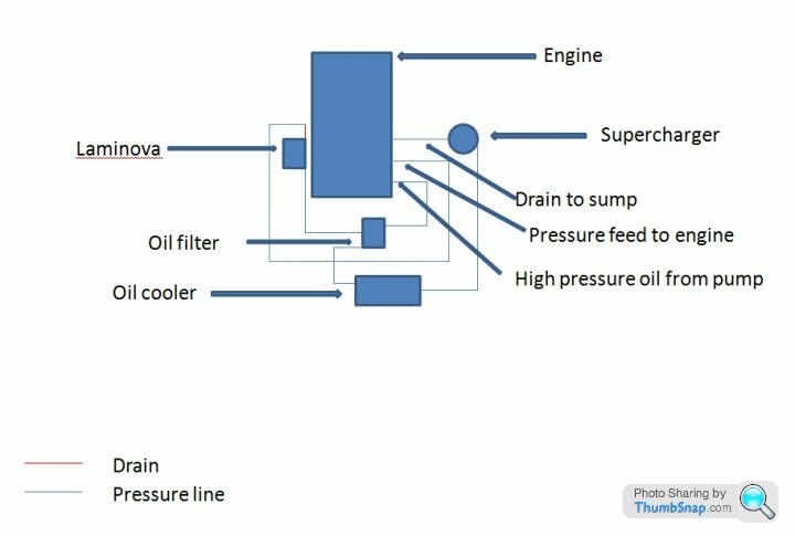
I need to run a remote filter due to space constraints, as you can see from the (rather elementary) design below, I'm planning on feeding the two oil circuits from two separate outputs after the filter. Fittings will be to suit the individual items involved (ie 10mm?) banjo bor the supercharger feed and then the relevant fittings on the oil coolers etc.
I know bu99er all about fluid dynamics etc, so I'm feeling rather out of my depth on this, my main concern being that I compromise the main oil pressure feed to the crank. Any thoughts or feedback most appreciated.
Some information: the supercharger is a centrifugal Turbo Technics one as fitted to their Elise supercharger kits (albeit now going in my Triumph Spitfire). When originally fitted I understand that there were two oil coolers - one for the supercharger circuit and another for the main engine oil feed.
I need to run a remote filter due to space constraints, as you can see from the (rather elementary) design below, I'm planning on feeding the two oil circuits from two separate outputs after the filter. Fittings will be to suit the individual items involved (ie 10mm?) banjo bor the supercharger feed and then the relevant fittings on the oil coolers etc.
I know bu99er all about fluid dynamics etc, so I'm feeling rather out of my depth on this, my main concern being that I compromise the main oil pressure feed to the crank. Any thoughts or feedback most appreciated.
Why an oil-to-air, AND an oil-to-water (Laminova) coolers?
How will you control the relative flows to them?
A restrictor in the line to the one you want least flow it would do it, but how small?
As the Professor of Computational Dynamics would say, it'll be trial and error in the end.
John
How will you control the relative flows to them?
A restrictor in the line to the one you want least flow it would do it, but how small?
As the Professor of Computational Dynamics would say, it'll be trial and error in the end.
John
I can see some issues with that design.
The entire flow of the oil-to-air cooler is going to the supercharger. The oil cooler flow should be regulated by a stat - if it is, the supercharger won't get adequate oil flow when the stat is closed; if it isn't, the oil will be overcooled under some conditions. The supercharger will also throttle the oil flow through the oil-to-air cooler which will limit its effectiveness. Also, having the flow through the oil cooler bypass the main engine and return directly to the sump means that all this flow is being robbed from the engine lubrication circuit.
The laminova cooler is cooling the oil but obviously increasing the load on the water cooling system. This will already be working harder since the engine will be producing more heat. Does the cooling system have adequate spare capacity? Otherwise you might find it worth using an oil-to-air cooler for the main oil cooling since it will be far more effective to cool the oil directly. If so you should definitely use a stat. A good way to achieve that is with a takeoff plate that includes a thermostat. This does mean that the flow through the cooler is variable and the output is not suitable to be used to supply anything directly - you would mix it back into the uncooled oil flow (eg via the take off plate) and any separate flows you turbo/supercharger cooling etc would be taken off downstream from there via a suitable restricter.
Thanks for your thoughts folks. I had reservations about the whole "double oil cooler" thing. Turbo Technics obviously thought it was necessary (albeit using two air to oil coolers), however, I'll have far better cooling available with the engine mounted in the front rather than the mod mounted affair in the Elise.
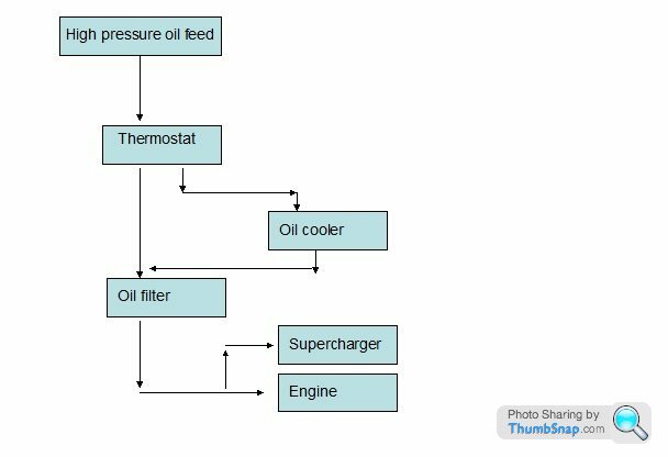
How about the below?
How about the below?
I don't really know, it may well have one. All I can see is that it has a small banjo bolt type attachment for the feed.
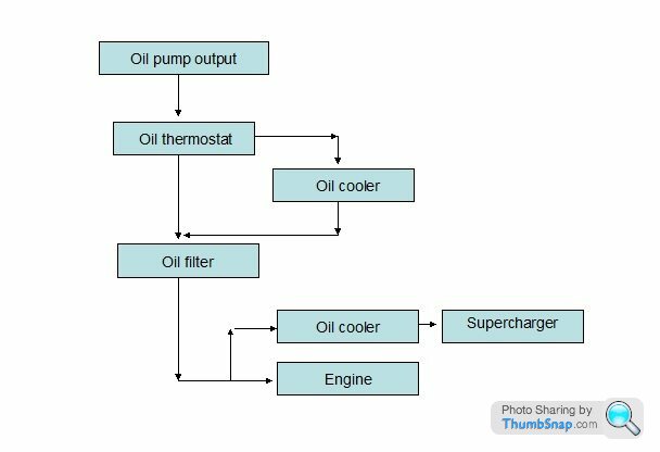
I've also been looking at some old info about this set up. It seems that the original design used an oil cooler in line to the SC feed, therefore I presume not thermostatically controlled. This cooler obviously had very little impact on overall oil temperature and, apparently they struggled with oil temperature on track. Therefore, for any serious use a second cooler was needed for the sump oil, hence the set up that came with what I bought. I think I can package both air to oil coolers, so will aim for that. Updated cooling circuit diagram to follow...
I've also been looking at some old info about this set up. It seems that the original design used an oil cooler in line to the SC feed, therefore I presume not thermostatically controlled. This cooler obviously had very little impact on overall oil temperature and, apparently they struggled with oil temperature on track. Therefore, for any serious use a second cooler was needed for the sump oil, hence the set up that came with what I bought. I think I can package both air to oil coolers, so will aim for that. Updated cooling circuit diagram to follow...
The TT supercharger uses a Rotrex friction epicyclic drive, there are no toothed gears, it totally relies on the friction generated by the compression loads from the annulus ring, passed through the planet rollers and onto the sun spindle. If you get too much slip, bad things happen!
Rotrex
Managing friction, but avoiding direct metal to metal contact in these units is key. Rotrex have their own oil spec, which runs i a separate loop (does not use engine oil loop). TT seem to run from engine loop, but this brings issues imo.
If it were mine, i'd run a separate loop, or at least a specific low particle size upstream filter and separate cooler!
(the cooler you run it, the higher the hoop stresses in the annulus and the bigger the clamp load on the drive) For a Rotrex drive, iirc (and it was a while ago) the drive was spec'd to run down to around minus 10degC (any lower and the annulus could fail or the sun shaft could get deformed)
Thanks for all the input, you're absolutely right of course about the drive for the SC, but the unit is one designed by TT (and badged either ROTTREX or Geotech) rather than being an actual Rotrex unit.
I'm not really sure how I'd go about driving a separate oil circuit- albeit I can see the benefits. I believe that the Rotrex units incorporate a pump in the supercharger. What sort of pump would I require?
Pragmatically, does my circuit (with the addition of another filter as you suggested) look like a sensible option?
Max_Torque said:
The TT supercharger uses a Rotrex friction epicyclic drive, there are no toothed gears, it totally relies on the friction generated by the compression loads from the annulus ring, passed through the planet rollers and onto the sun spindle. If you get too much slip, bad things happen!
Rotrex
Managing friction, but avoiding direct metal to metal contact in these units is key. Rotrex have their own oil spec, which runs i a separate loop (does not use engine oil loop). TT seem to run from engine loop, but this brings issues imo.
If it were mine, i'd run a separate loop, or at least a specific low particle size upstream filter and separate cooler!
(the cooler you run it, the higher the hoop stresses in the annulus and the bigger the clamp load on the drive) For a Rotrex drive, iirc (and it was a while ago) the drive was spec'd to run down to around minus 10degC (any lower and the annulus could fail or the sun shaft could get deformed)
Rotrex
Managing friction, but avoiding direct metal to metal contact in these units is key. Rotrex have their own oil spec, which runs i a separate loop (does not use engine oil loop). TT seem to run from engine loop, but this brings issues imo.
If it were mine, i'd run a separate loop, or at least a specific low particle size upstream filter and separate cooler!
(the cooler you run it, the higher the hoop stresses in the annulus and the bigger the clamp load on the drive) For a Rotrex drive, iirc (and it was a while ago) the drive was spec'd to run down to around minus 10degC (any lower and the annulus could fail or the sun shaft could get deformed)
Edited by itiejim on Tuesday 17th January 12:28
Edited by itiejim on Tuesday 17th January 12:39
itiejim said:
Thanks for all the input, you're absolutely right of course about the drive for the SC, but the unit is one designed by TT (and badged either ROTTREX or Geotech) rather than being an actual Rotrex unit.
I'm not really sure how I'd go about driving a separate oil circuit- albeit I can see the benefits. I believe that the Rotrex units incorporate a pump in the supercharger. What sort of pump would I require?
Pragmatically, does my circuit (with the addition of another filter as you suggested) look like a sensible option?
TT brought the Rotrex friction drive technology. They didn't design it from scratch themselves for two reasons:I'm not really sure how I'd go about driving a separate oil circuit- albeit I can see the benefits. I believe that the Rotrex units incorporate a pump in the supercharger. What sort of pump would I require?
Pragmatically, does my circuit (with the addition of another filter as you suggested) look like a sensible option?
Max_Torque said:
The TT supercharger uses a Rotrex friction epicyclic drive, there are no toothed gears, it totally relies on the friction generated by the compression loads from the annulus ring, passed through the planet rollers and onto the sun spindle. If you get too much slip, bad things happen!
Rotrex
Managing friction, but avoiding direct metal to metal contact in these units is key. Rotrex have their own oil spec, which runs i a separate loop (does not use engine oil loop). TT seem to run from engine loop, but this brings issues imo.
If it were mine, i'd run a separate loop, or at least a specific low particle size upstream filter and separate cooler!
(the cooler you run it, the higher the hoop stresses in the annulus and the bigger the clamp load on the drive) For a Rotrex drive, iirc (and it was a while ago) the drive was spec'd to run down to around minus 10degC (any lower and the annulus could fail or the sun shaft could get deformed)
Rotrex
Managing friction, but avoiding direct metal to metal contact in these units is key. Rotrex have their own oil spec, which runs i a separate loop (does not use engine oil loop). TT seem to run from engine loop, but this brings issues imo.
If it were mine, i'd run a separate loop, or at least a specific low particle size upstream filter and separate cooler!
(the cooler you run it, the higher the hoop stresses in the annulus and the bigger the clamp load on the drive) For a Rotrex drive, iirc (and it was a while ago) the drive was spec'd to run down to around minus 10degC (any lower and the annulus could fail or the sun shaft could get deformed)
Edited by itiejim on Tuesday 17th January 12:28
Edited by itiejim on Tuesday 17th January 12:39
1) Rotrex hold the patents and they are quite robust
2) It's really rather hard to drive a decent friction drive epicyclic transmission. Beyond the resource available to TT
As you say, the Rotrex unit has a built in oil pump, presumably not fitted to the TT unit. iirc, the Rotrex has a hollow sun shaft and pumps oil up the middle of that shaft, which is centrifuged out and hence acts as a traction film between the rolling elements of the drive. Their oil specification/blend attempts to be non-Newtonian, and stiffens under high pressure to transfer the load between the elements.
I'd imagine the TT unit, using just engine oil, either runs with a higher hoop stress, or more likely, tuns at a lower peak loading to avoid excessive slip.
The one thing these drives REALLY hate is high torsional vibration, like on engine start, rapid gearshifts, or lightweight rotating (race) engines, where the second order crank accelerations from firing events are large.
Thank you for the additional information.
My application will be principally for road use, flywheel and clutch will be lighter than standard, but not race-engine light and gear changes will be no faster than a sympathetically used Ford Type 9 can cope with.
Given the feedback, my understanding is that it's OK to build the system as per my previous diagram with the addition of an online filter immediately before the charger(?). I see there are a variety of these available, any advice on what grade filter I should use - 80 microns seems quite common.

Gassing Station | Engines & Drivetrain | Top of Page | What's New | My Stuff