What Engine for 500BHP
Discussion


stevieturbo said:
Yep, all are options.
External controller like aquamist can simplify things to a degree, as it's one package, just install it, all easy.
But there's a lot to be said for ecu control if it can do it too and it will be cheaper for the actual install.
Obviously there will be tuning time, but that's going to apply anyway
The simplicity of the install for the Aquamist system is not as simple as it first seems... Yes its all one package, but I would need to find somewhare for the Dash Gauge and the controller - not difficult, but the dash is already full...External controller like aquamist can simplify things to a degree, as it's one package, just install it, all easy.
But there's a lot to be said for ecu control if it can do it too and it will be cheaper for the actual install.
Obviously there will be tuning time, but that's going to apply anyway
I have checked the ECU and I have 2 spare PWM outputs that I can use, so I just need to decide if I should control the pump or use an aquamist FAV.
You mention a need for tuning...
If I just spray some Water/Meth, what effect would that have. I realise to get more power, a new tune would be required, but does the Water/Meth affect the AFR's?
What do you use Water or 50/50 water/Meth?

Any thoughts on Nozzle location ??
I was thinking of just after the Charge cooler, to get the best mixing before the engine, but then there is a chance of a small amount of th einjected liquid escaping from the dump valve when it opens. Would this be a problem if using 50/50 mixture?
The alternate would be between the Dump Valve and Air temp sensor, but that would be quite close to the temperature sensor....
stevieturbo said:
after the charge cooler sounds fine.
Or if going Aquamist and FAV, you could opt for 6 small nozzles, 1 in each runner.
Or even without the FAV, they do small nozzles with built in check valves so they can be installed in the intake.
that would ensure equal flow to each cylinder
So no worries about a bit ow water/Meth coming out of the Dump valve then. I assume a 50/50 mix isnt flamable anyway?Or if going Aquamist and FAV, you could opt for 6 small nozzles, 1 in each runner.
Or even without the FAV, they do small nozzles with built in check valves so they can be installed in the intake.
that would ensure equal flow to each cylinder
I did think of putting one nozzle in each runner, but that is a lot more work
 also as i was planning to use the Air temperature sensor as a fail safe, or try it as a control parameter & that wouldnt work if i have the nozzles on the runners.
System wise I have gone with a Devils Own pump, nozzle & fittings for stainless hoses & an Aquamist FAV for control. The tank is also an Aquamist one, just because it fits better in my boot...
stevieturbo said:
You can spray onto the sensor and use it as a failsafe...but remember, the temp sensors are very very slow for that sort of thing. The flow meter etc would be a better option.
That said, the modern stuff is very reliable these days anyway, ad if the ecu has good knock and wideband control...you should be well covered. And if you're only using a small amount and not tuning aggressively for more power....there really isnt a lot to worry about anyway
And most of them use an Aquatec DD5800 pump, not sure if any still use the Shurflo.
And I had my BOV close to the nozzles for years even with 100% meth. Some probably comes out, but it evaporates or disperses quickly...it would never be anywhere that would pose a risk. With 50/50 there really would be zero risk.
I wasnt planning to spray directly on the sensor, just somewhere before the sensor.. yes they are slow, but it would pick up a partially blocked nozzle. I need to look into adding a flow sensor, as I am not sure if i have any available inputs.That said, the modern stuff is very reliable these days anyway, ad if the ecu has good knock and wideband control...you should be well covered. And if you're only using a small amount and not tuning aggressively for more power....there really isnt a lot to worry about anyway
And most of them use an Aquatec DD5800 pump, not sure if any still use the Shurflo.
And I had my BOV close to the nozzles for years even with 100% meth. Some probably comes out, but it evaporates or disperses quickly...it would never be anywhere that would pose a risk. With 50/50 there really would be zero risk.
The Knock control I have seems to work ok, so that would be the true safety. With the air temperature, I was going to use it to inject more as the temps rise, so Map vs air temp for the PWM table.
If you had no issues injecting before the BOV, then I think I will try there first, as it gives more time for mixing...
stevieturbo said:
And again....dont misunderstand that the bulk of what water injection does happens in the combustion chamber. Not the charge cooling although that can be a welcome benefit too.
But when charge temps arent high to start with...in that respect the WI would be doing nothing, which is very far from the truth.
So mixing....hard to say if that's the right word. Clearly 1 inj per cylinder will give the best distribution, no different than you wouldnt normally inject fuel way down the boost pipe.
You may not be able to see what the WI is doing in terms of charge temps spraying near a sensor...but the WI will absolutely be doing it's job in the chamber.
Yes a bit of missunderstanding on my part.... I was assuming most of the benefit was in teh charge cooling, not in the actual combustion process - we learn something every day But when charge temps arent high to start with...in that respect the WI would be doing nothing, which is very far from the truth.
So mixing....hard to say if that's the right word. Clearly 1 inj per cylinder will give the best distribution, no different than you wouldnt normally inject fuel way down the boost pipe.
You may not be able to see what the WI is doing in terms of charge temps spraying near a sensor...but the WI will absolutely be doing it's job in the chamber.
227bhp said:
turbonutter said:
Any thoughts on Nozzle location ??
Your CC could do with twisting round a bit so the hoses are pointing upright, potential for air pockets there even if you've twisted it after it's been bled. Hope it's flowing countercurrent!stevieturbo said:
Thanks - found some usefull info there... stevieturbo said:
Generally check valves are only needed if the nozzles are in the intake...ie to prevent vacuum sucking in water.
Or some have a check valve is the water reservoir etc is higher than the nozzle...so gravity would allow fluid to syphon in.
Either way, fitment of the FAV or solenoid covers both of these issues as the solenoid will close to prevent fluid moving.
That is what I thought, but worth checking👍Or some have a check valve is the water reservoir etc is higher than the nozzle...so gravity would allow fluid to syphon in.
Either way, fitment of the FAV or solenoid covers both of these issues as the solenoid will close to prevent fluid moving.
stevieturbo said:
Generally check valves are only needed if the nozzles are in the intake...ie to prevent vacuum sucking in water.
Or some have a check valve is the water reservoir etc is higher than the nozzle...so gravity would allow fluid to syphon in.
Either way, fitment of the FAV or solenoid covers both of these issues as the solenoid will close to prevent fluid moving.
That is what I thought, but worth checking👍Or some have a check valve is the water reservoir etc is higher than the nozzle...so gravity would allow fluid to syphon in.
Either way, fitment of the FAV or solenoid covers both of these issues as the solenoid will close to prevent fluid moving.
SO I am now back from work, its been a long trip, suffice to say the chinese ships we had built took a while to get finished.....
Anyway I am just in the process of hooking up the wiring for my Water Injection. The question I have is regarding the Aquamist Fast Acting Solenoid valve that I am using to control the Water Injection Flow. This will be controlled from my ECU, using a Low side PWM Signal. I was just about to run a +12V to the coil, and noticed it is marked 6Vdc.
My question is how to best connect the coil, I have either an unregulated 12V or a regulated +5V to choose from.
Should I use the 12V, but limit the PWM signal to a maximum of 50%, or should i use +5V. My thinking is if I use +5V the valve wont open fully ?
Cheers
thecarbuilder246 said:
Hi
This is for turbonutter.
I came across your Mr2 gearbox upgrade while searching the web.
This is something I'm trying to do but using a cosworth V6 instead of the alfa engine in a 246 Dino rep.
I've done something similar to you and mounted the gearbox on the crank case and everything seems fine.
So what I'm after is someone to make an adaptor plate to mount the two together. Ideally I'd like it in 12mjm
if possible.
Ian
Ford to Alfa Adapter plate is not something that I have or can get... not sure why you would put a ford engine in an italian car either, but if thats what you want, then you need to get a local engineering company to make up the adapter. This is for turbonutter.
I came across your Mr2 gearbox upgrade while searching the web.
This is something I'm trying to do but using a cosworth V6 instead of the alfa engine in a 246 Dino rep.
I've done something similar to you and mounted the gearbox on the crank case and everything seems fine.
So what I'm after is someone to make an adaptor plate to mount the two together. Ideally I'd like it in 12mjm
if possible.
Ian
I used DJM Motorsport for mine, as they are local to me. http://www.djm-motorsport.co.uk/Design_Transmissio... but its not cheap for a one off.... Is there not a ford gearbox that will fit?
thecarbuilder246 said:
Hi
I see from your website post that you used an hydraulic clutch release bearing. As I'm stuck for space I intend to do the same.
Can I ask what bearing you used-tilton? You also made up a spacer. Was this to mount the bearing or so you could used the tilton clutch?
ian
I only used a hydraulic release bearing as the exhaust was in the way of the standard toyota clutch slave cylinder.I see from your website post that you used an hydraulic clutch release bearing. As I'm stuck for space I intend to do the same.
Can I ask what bearing you used-tilton? You also made up a spacer. Was this to mount the bearing or so you could used the tilton clutch?
ian
I used a Tilton 800 Series - 44mm contact 1.6" Tall Part# 61-8002.
They come in various heights - I used this one as I already had it fitted to my alfa gearbox.
The Spacer/mounting block, was to be able to mount the release bearing to the gearbox.
OK its been a while since I updated the thread, for various reasons I didnt manage to get the WI mapped until yesterday. The installation was completed a while ago, but with work etc I never made it to the dyno... One of the hiccups was a fault with the ECU, the H-Bridge chip for the DBW failed so the throttle would only move from rest to full open & not from rest to close... Not happy about that, as the ECU has had very little use...
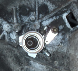
Anyway Installed the nozzle as shown below after the dump valve and before the air temp sensor

I did some flow testing by controlling the solenoid opening & found I only got about 1/3 of the range using the solenoid as i did controlling the pump speed to give a pressure range of 60-200psi. so I decided to control the flow with the Pump and just use the solenoid to start the injection (the pump starting slightly before, maybe its not necessary like that, but it was wired up...
The plan for the rolling road was to map the boost control from 2000-3500 rpm, as by having no control there, due to installing a softer spring, I was loosing boost and power. With the softer spring, the 3 port boost solenoid was already maxed out to get 1.1 bar boost, so I planned to change for a 4 port valve, so we could up the boost once the water injection was running. However we found that the 4 port valve was too sensitive around the point where we needed the most control (possibly because the valve was around 50% open?) so we had to go back to the 3 port valve. I could have got more boost by changing the spring, but I didnt want to loose the flexibility by also increasing the minimum boost... So decided to see what happened with the boost available...
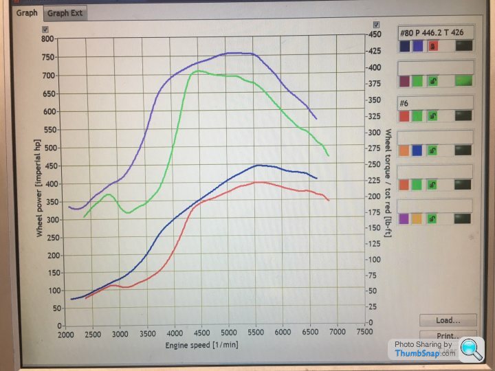
We started the WI at 0.4 bar, increasing the flow as boost and rpm rises & it allowed about 10 degrees of ignition to be added & increased the wheel power from 403 to 452, so over 500 at the fly wheel again - which was all I was looking for at the moment.
https://www.facebook.com/neil.simons.319/videos/12...
Just need to add in a flow sensor to give me some extra safety rather than relying on the knock control. I will use the flow switch to switch ign & fuel maps if the flow fails...
Interestingly we now have less boost, I think due to the extra gas volume increasing the Exhaust pressure? so once I add a second boost solenoid we should be able to get the boost back again... but I will be leaving it like this for a while...
Figures below are before and after - Torque at the top.. its a hub dyno so wheel figures..
Anyway Installed the nozzle as shown below after the dump valve and before the air temp sensor
I did some flow testing by controlling the solenoid opening & found I only got about 1/3 of the range using the solenoid as i did controlling the pump speed to give a pressure range of 60-200psi. so I decided to control the flow with the Pump and just use the solenoid to start the injection (the pump starting slightly before, maybe its not necessary like that, but it was wired up...
The plan for the rolling road was to map the boost control from 2000-3500 rpm, as by having no control there, due to installing a softer spring, I was loosing boost and power. With the softer spring, the 3 port boost solenoid was already maxed out to get 1.1 bar boost, so I planned to change for a 4 port valve, so we could up the boost once the water injection was running. However we found that the 4 port valve was too sensitive around the point where we needed the most control (possibly because the valve was around 50% open?) so we had to go back to the 3 port valve. I could have got more boost by changing the spring, but I didnt want to loose the flexibility by also increasing the minimum boost... So decided to see what happened with the boost available...
We started the WI at 0.4 bar, increasing the flow as boost and rpm rises & it allowed about 10 degrees of ignition to be added & increased the wheel power from 403 to 452, so over 500 at the fly wheel again - which was all I was looking for at the moment.
https://www.facebook.com/neil.simons.319/videos/12...
Just need to add in a flow sensor to give me some extra safety rather than relying on the knock control. I will use the flow switch to switch ign & fuel maps if the flow fails...
Interestingly we now have less boost, I think due to the extra gas volume increasing the Exhaust pressure? so once I add a second boost solenoid we should be able to get the boost back again... but I will be leaving it like this for a while...
Figures below are before and after - Torque at the top.. its a hub dyno so wheel figures..
The three port works fine, but with the spring I am running with 100% duty I could only get about 210kpa, with the WI flowing this drops to 190kpa. to get more I would need a bigger spring, which I dont want to do.
The 4 port we tried just vents to atmosphere, with no restriction.. rather than mess more with the 4 port we decided to go with a second 3 port to control the signal to the bottom of the WG, starting to bleed this one when the 3 port is nearly maxed out - I have the 3 port valve & a spare PWM channel, so its just a matter of fitting and wiring it....
The 4 port we tried just vents to atmosphere, with no restriction.. rather than mess more with the 4 port we decided to go with a second 3 port to control the signal to the bottom of the WG, starting to bleed this one when the 3 port is nearly maxed out - I have the 3 port valve & a spare PWM channel, so its just a matter of fitting and wiring it....
GreenV8S said:
I thought it was generally best with WI to pulse at higher pressure rather than stay on continuously at lower pressure, so you get better atomisation. If the solenoid was restricting the flow, have you checked whether you are getting the duty cycle up to 100%?
The solenoid was not restricting the flow more than a few CC, but the range of possible flow was less. with the pump at full speed and controlling only the solenoid i measured 390 to 450cc/min and with the solenoid full open and controlling the pump gave 280 to 450cc range.the 280cc is with 30% duty on the pump which netted 65psi before the nozzle. Minimum for good spray 60psi as per the makers, but it tested ok down to 50psi.
GreenV8S said:
turbonutter said:
The solenoid was not restricting the flow more than a few CC, but the range of possible flow was less. with the pump at full speed and controlling only the solenoid i measured 390 to 450cc/min and with the solenoid full open and controlling the pump gave 280 to 450cc range.
the 280cc is with 30% duty on the pump which netted 65psi before the nozzle. Minimum for good spray 60psi as per the makers, but it tested ok down to 50psi.
Are you saying the problem is the solenoid wasn't capable reducing the flow as low as you wanted? That suggests either the PWM frequency was wrong, or the controller wasn't generating the full range of duty cycles 0 - 100%. I guess it's academic anyway.the 280cc is with 30% duty on the pump which netted 65psi before the nozzle. Minimum for good spray 60psi as per the makers, but it tested ok down to 50psi.
Gassing Station | Engines & Drivetrain | Top of Page | What's New | My Stuff