What Engine for 500BHP
Discussion


turbonutter said:
Liquid Knight said:
Have you given any thought to the UK Power Tour?
I made an honest observation about PPC and they're not talking to me yet.
The Power tour would be great, but I doubt that the Engine will be rebuilt by then I made an honest observation about PPC and they're not talking to me yet.

I havent been in touch with PPC for a while - must remember not to mention your name!
OK so I am still away at work, so no progress on the car its self, but I think I have decided to stick with the Haltech & pretty sure I have got someone who will do a decent job of the mapping this time.
Also have decided to bin the two Davis Craig cooling pumps & re-install the stock alfa pump. It will mean som modifications to the pipe connections on the engine, but somthing that isnt too difficult. I also plan to fit a remote thermostat close to the radiator. This is for two reasons one is that the alfa thermostat hosing wont fit due to the turbocharger being in the way & the second is so that i can fit a booster pump in the main coolant circuit.
This will be a Stewart components E558 pump, which flows 210l/min compared to the 115L/min of the Davis craig ones.
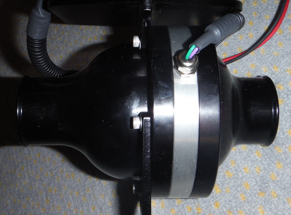
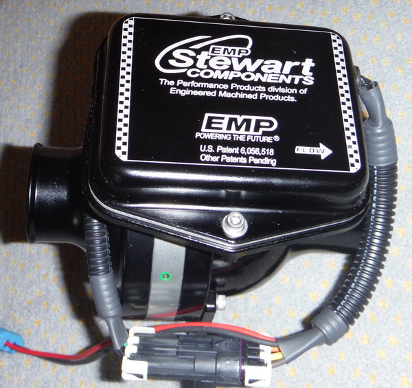

This is a much nicer pump - it looks 100times better than the DC ones, is made from all aluminium & has propper o-ring seals, so wont leak at the slightest provocation like the DC ones!
Also have decided to bin the two Davis Craig cooling pumps & re-install the stock alfa pump. It will mean som modifications to the pipe connections on the engine, but somthing that isnt too difficult. I also plan to fit a remote thermostat close to the radiator. This is for two reasons one is that the alfa thermostat hosing wont fit due to the turbocharger being in the way & the second is so that i can fit a booster pump in the main coolant circuit.
This will be a Stewart components E558 pump, which flows 210l/min compared to the 115L/min of the Davis craig ones.
This is a much nicer pump - it looks 100times better than the DC ones, is made from all aluminium & has propper o-ring seals, so wont leak at the slightest provocation like the DC ones!
I'd just fit the std mech pump and be done with it.
If you take a look at the cooling system layout for an MGF, the later cars (TF's) used two thermostats to avoid extreme thermal cycling (and the resultant K series head gasket failures!) IIRC, one was in the normal location on the water pump inlet, the second remote one (actually a LR part from the 3.9 disco iirc) was mounted on the rear bulkhead. By using two stats, the engine would avoid getting a large slug of very cold water when the 1st stat cracked open, and hence avoid a lot of thermal shock. I'd imagine google would bring up a diagram etc
If you take a look at the cooling system layout for an MGF, the later cars (TF's) used two thermostats to avoid extreme thermal cycling (and the resultant K series head gasket failures!) IIRC, one was in the normal location on the water pump inlet, the second remote one (actually a LR part from the 3.9 disco iirc) was mounted on the rear bulkhead. By using two stats, the engine would avoid getting a large slug of very cold water when the 1st stat cracked open, and hence avoid a lot of thermal shock. I'd imagine google would bring up a diagram etc
Max_Torque said:
I'd just fit the std mech pump and be done with it.
If you take a look at the cooling system layout for an MGF, the later cars (TF's) used two thermostats to avoid extreme thermal cycling (and the resultant K series head gasket failures!) IIRC, one was in the normal location on the water pump inlet, the second remote one (actually a LR part from the 3.9 disco iirc) was mounted on the rear bulkhead. By using two stats, the engine would avoid getting a large slug of very cold water when the 1st stat cracked open, and hence avoid a lot of thermal shock. I'd imagine google would bring up a diagram etc
The Electric pump is needed on these stratos type replicas. When I say needed, that is not entierly true, but lets say they help a lot and avoid having to sit in traffic with the engine revving to 2000rpm on a hot day, just to keep things cool. The problem is the extra 4or5m of piping needed to get the water to the radiator, that the OEM pump wasnt designed for. It also dosent help that most of that piping is only 32mm diameter, as that is all that fits down the central spine.If you take a look at the cooling system layout for an MGF, the later cars (TF's) used two thermostats to avoid extreme thermal cycling (and the resultant K series head gasket failures!) IIRC, one was in the normal location on the water pump inlet, the second remote one (actually a LR part from the 3.9 disco iirc) was mounted on the rear bulkhead. By using two stats, the engine would avoid getting a large slug of very cold water when the 1st stat cracked open, and hence avoid a lot of thermal shock. I'd imagine google would bring up a diagram etc
Thanks for the tip on the MGF cooling system - I will have a look at how that works....
turbonutter said:
Max_Torque said:
I'd just fit the std mech pump and be done with it.
If you take a look at the cooling system layout for an MGF, the later cars (TF's) used two thermostats to avoid extreme thermal cycling (and the resultant K series head gasket failures!) IIRC, one was in the normal location on the water pump inlet, the second remote one (actually a LR part from the 3.9 disco iirc) was mounted on the rear bulkhead. By using two stats, the engine would avoid getting a large slug of very cold water when the 1st stat cracked open, and hence avoid a lot of thermal shock. I'd imagine google would bring up a diagram etc
The Electric pump is needed on these stratos type replicas. When I say needed, that is not entierly true, but lets say they help a lot and avoid having to sit in traffic with the engine revving to 2000rpm on a hot day, just to keep things cool. The problem is the extra 4or5m of piping needed to get the water to the radiator, that the OEM pump wasnt designed for. It also dosent help that most of that piping is only 32mm diameter, as that is all that fits down the central spine.If you take a look at the cooling system layout for an MGF, the later cars (TF's) used two thermostats to avoid extreme thermal cycling (and the resultant K series head gasket failures!) IIRC, one was in the normal location on the water pump inlet, the second remote one (actually a LR part from the 3.9 disco iirc) was mounted on the rear bulkhead. By using two stats, the engine would avoid getting a large slug of very cold water when the 1st stat cracked open, and hence avoid a lot of thermal shock. I'd imagine google would bring up a diagram etc
Thanks for the tip on the MGF cooling system - I will have a look at how that works....
If we assume the flow rate of the pump is linear with drive speed (which it isn't due to various reasons, but it's close in reality) then at idle the flow rate of the system will be something like 12x lower than at peak rpm. Hence the pressure "losses" of the plumbing will also be commensurately lower. As such, at idle, the "small" pipework creates practically zero restriction, and the flow rate is unaffected! Added to which, the heat rejection of the system is fundamentally controlled by the performance of the radiator system. If the flow rate falls, then all that happens is the system delta T increases. Total heat flux remains constant.
Reving the engine to 2000rpm will not help matters, quite the opposite in fact. (total heat flux will increase (more fuel being burnt), and cooling system temp will increase, not fall!)
Then there is the small matter of the fact that the "extra" pipework you talk about really isn't a restriction, due to it being "smooth and linear". Compared to the pressure loss from the head gasket / thermostat and radiator the flow loss purely due to the extra pipe work will be vanishingly small!
I would say, that there is a better than 50:50 chance that the largest restriction you could add to the system would be an additional electric pump.............
Max_Torque said:
turbonutter said:
Max_Torque said:
I'd just fit the std mech pump and be done with it.
If you take a look at the cooling system layout for an MGF, the later cars (TF's) used two thermostats to avoid extreme thermal cycling (and the resultant K series head gasket failures!) IIRC, one was in the normal location on the water pump inlet, the second remote one (actually a LR part from the 3.9 disco iirc) was mounted on the rear bulkhead. By using two stats, the engine would avoid getting a large slug of very cold water when the 1st stat cracked open, and hence avoid a lot of thermal shock. I'd imagine google would bring up a diagram etc
The Electric pump is needed on these stratos type replicas. When I say needed, that is not entierly true, but lets say they help a lot and avoid having to sit in traffic with the engine revving to 2000rpm on a hot day, just to keep things cool. The problem is the extra 4or5m of piping needed to get the water to the radiator, that the OEM pump wasnt designed for. It also dosent help that most of that piping is only 32mm diameter, as that is all that fits down the central spine.If you take a look at the cooling system layout for an MGF, the later cars (TF's) used two thermostats to avoid extreme thermal cycling (and the resultant K series head gasket failures!) IIRC, one was in the normal location on the water pump inlet, the second remote one (actually a LR part from the 3.9 disco iirc) was mounted on the rear bulkhead. By using two stats, the engine would avoid getting a large slug of very cold water when the 1st stat cracked open, and hence avoid a lot of thermal shock. I'd imagine google would bring up a diagram etc
Thanks for the tip on the MGF cooling system - I will have a look at how that works....
If we assume the flow rate of the pump is linear with drive speed (which it isn't due to various reasons, but it's close in reality) then at idle the flow rate of the system will be something like 12x lower than at peak rpm. Hence the pressure "losses" of the plumbing will also be commensurately lower. As such, at idle, the "small" pipework creates practically zero restriction, and the flow rate is unaffected! Added to which, the heat rejection of the system is fundamentally controlled by the performance of the radiator system. If the flow rate falls, then all that happens is the system delta T increases. Total heat flux remains constant.
Reving the engine to 2000rpm will not help matters, quite the opposite in fact. (total heat flux will increase (more fuel being burnt), and cooling system temp will increase, not fall!)
Then there is the small matter of the fact that the "extra" pipework you talk about really isn't a restriction, due to it being "smooth and linear". Compared to the pressure loss from the head gasket / thermostat and radiator the flow loss purely due to the extra pipe work will be vanishingly small!
I would say, that there is a better than 50:50 chance that the largest restriction you could add to the system would be an additional electric pump.............
Also a number of other "strat" owners have installed electric booster pumps & that has cured the issue they had with overheating in traffic......
turbonutter said:
I could be wrong with the theory, all i know is that it worked! Sitting with my last car stationary & with water temps rising above normal, revving the engine brought the temps back down!
Also a number of other "strat" owners have installed electric booster pumps & that has cured the issue they had with overheating in traffic......
My experience with my early S1 Elise (which everyone thinks has a crap cooling system) is that if there is any air in the system at all, it will be unable to control coolant temps at idle. Once it is bled 99.999% it is perfectly fine, even in our Australian 40°C+ ambient temps.Also a number of other "strat" owners have installed electric booster pumps & that has cured the issue they had with overheating in traffic......
On the other hand, more than one of my German Elise-owning friends and acquaintances are adamant that an electric coolant pump is absolutely necessary.
Work that one out...
Edited by AER on Friday 22 November 00:32

It would be good to have some kind of flowmeter that could be used to measure the actual flow & see if the electric pump does indeed make any difference...
Probably the easiest would be to monitor the cooling flow through the turbo to the headder tank, as this is only a -4 hose it wouldnt need a huge flowmeter and the flow here will change as the main flow changes.
Obviously measuring the flow into the engine would be better, but finding a flowmeter to handle that flow is going to be expensive... Any one with any thoughts on this?? or any ideas where to get a reasonably priced flowmeter from??
TheRealFingers99 said:
Just a thought: why not consider going waterless/pressureless? Hell, with a car that gorgeous you might even get some free in a sponsorship deal!
This is somthing that I have looked into and now the system is drained would be a perfect time to do it. The question is does this waterless coolant work - I assume you mean the Evans Brand.Yes according to the website its fantastic stuff, but I havent found any independent tests that confirm this, so if anyone is using the stuff is it any good????
turbonutter said:
It would be good to have some kind of flowmeter that could be used to measure the actual flow & see if the electric pump does indeed make any difference...
Probably the easiest would be to monitor the cooling flow through the turbo to the headder tank, as this is only a -4 hose it wouldnt need a huge flowmeter and the flow here will change as the main flow changes.
Obviously measuring the flow into the engine would be better, but finding a flowmeter to handle that flow is going to be expensive... Any one with any thoughts on this?? or any ideas where to get a reasonably priced flowmeter from??
http://www.ebay.co.uk/itm/like/290870207046?lpid=83&device=c&adtype=pla&crdt=0&ff3=1&ff11=ICEP3.0.0&ff12=67&ff13=80&ff14=83Probably the easiest would be to monitor the cooling flow through the turbo to the headder tank, as this is only a -4 hose it wouldnt need a huge flowmeter and the flow here will change as the main flow changes.
Obviously measuring the flow into the engine would be better, but finding a flowmeter to handle that flow is going to be expensive... Any one with any thoughts on this?? or any ideas where to get a reasonably priced flowmeter from??
http://www.ebay.com/bhp/digital-water-flow-meter
??
Somthing like this could work,
http://www.ebay.co.uk/itm/1-2-LCD-Water-Flow-Senso...
Of course only a temporary install in the turbo cooling line,
But the DP idea might be easier
http://www.ebay.co.uk/itm/1-2-LCD-Water-Flow-Senso...
Of course only a temporary install in the turbo cooling line,
But the DP idea might be easier
Max_Torque said:
Just measure the delta pressure across the rad............
Not sure why we are focussing on flow when what we are interested ultimately is cooling. So Why not measure the outlet and inlet temperatures on the engine block to get the delta - if the pump works, the delta would increase and if it makes no difference the delta would remain the same.
Gassing Station | Engines & Drivetrain | Top of Page | What's New | My Stuff