Fuel Pump speed control
Discussion


Pat_T said:
Max_Torque said:
I've got a VDO fuel pump driver module, Ford Part number 3W 83-9D372-AB, VDO number A2C53005489, off a Range Rover. It has a 6 pin connector which pinsout as follows:
1) 12v output to fuel pump
2) 0v return (low side PWM) from pump
3) pump drive signal from eng ecu, 60 to 330Hz, drive with open collector low side drive, 0 to 50% duty is 0 to 100% pump duty
4) not used
5) 12V power feed, ignition switched
6) 0v chassis ground
The unit uses a MLX16201 "smart" relay controller internally (no CAN coms) and an infineon BTS202Z low side driver to run the pump. I've not beasted mine yet, but it looks good for something like 10A continuously, so should run a reasonable sized fuel pump.
Max_T, (hoping you're still reading this)1) 12v output to fuel pump
2) 0v return (low side PWM) from pump
3) pump drive signal from eng ecu, 60 to 330Hz, drive with open collector low side drive, 0 to 50% duty is 0 to 100% pump duty
4) not used
5) 12V power feed, ignition switched
6) 0v chassis ground
The unit uses a MLX16201 "smart" relay controller internally (no CAN coms) and an infineon BTS202Z low side driver to run the pump. I've not beasted mine yet, but it looks good for something like 10A continuously, so should run a reasonable sized fuel pump.
I'm now doing the schematic drawings for my engine and data looms. Am I right in thinking that using the Jag VDO driver module, I no longer need a fuel pump relay and I can run the PWM signal from ECU direct to driver module, then 12V output direct to fuel pump?
cheers,
Patrick
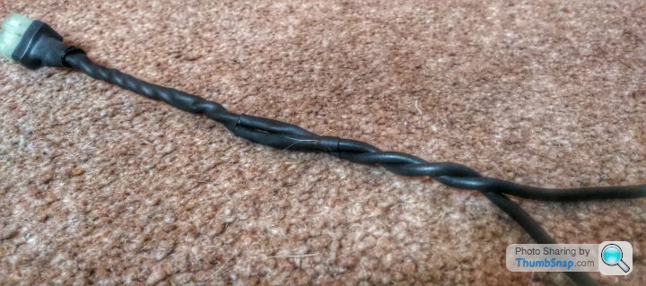
Fuse (15 or 20A) a nice beefy wired spur to the Driver module, make sure there is a good chassis earth close by, and twist the + and - wires together to the fuel pump to minimise stray inductance and hence limit any PWM noise etc
Brilliant yep can ensure all those things.
Meanwhile I have also been thinking about the PWM control strategies:
Fuel pressure control strategy
o Set mechanical pressure regulator to 4.0bar.
o Fit 0-5bar, 0-5V fuel pressure sensor, calibrate to mechanical gauge.
o Fuel pressure 0 – 3.6 bar -> increase pulse width duty
o Fuel pressure 3.6-3.8 bar -> maintain duty
o Fuel pressure >3.8bar -> decrease pulse width duty
This control strategy needs to work at a minimum of 500hz? I think the ECU can read sensor inputs at upto 2000hz. Should I put together a matrix/table of PWM duties. What resolution do you think would be appropriate, 5% steps? How would you approach this?
For interest on the Pierburg EWP I was going to do the following
Electric waterpump + fan control strategies
o water temp 0°C - 70°C -> slow cycle – 25%* duty?
o water temp 70°C - 90°C -> medium cycle 50%* duty?
o water temp 90°C - 98°C -> medium cycle 75%* duty? – this is the band to try and maintain.
o water temp – 98°C – 105°C -> max cycle 99%* duty
o Water above 105°C – 1x fan on.
o Water above 110°C – 2x fan on.
o Oil above 125°C – 2x fan on. Automatic switch to max duty if not already there.
(*exact figures to be determined during rolling road testing.)
I have a Cosworth Omega digital dash which I plan to set Alarms on for the following:
o Oil temp - 134°C
o Water temp - 111°C
o Fuel pressure – under 3.2bar
all sound sensible? would be interested to hear your thoughts.
cheers,
Patrick
Edited by Pat_T on Tuesday 23 June 10:39
Assuming you don't have a closed loop control "channel" available in your ecu, that can drive the PWM output with a PID or similar control strategy, then using a lookup table with fuel pressure as the x axis and pwm as the Y will give you some measure of control. (in effect, it will be the "P" (proportional) bit of a PID controller, and hence be unable to get the fuel pressure exactly on target)
If you also assign an injector pulse width trim table to fuel pressure, then having an exact rail pressure doesn't matter, because the pulse width will be modified to suit the actual injector differential pressure.
If you do use a look up table as a crude Proportional Control channel, then you are going to have to find a compromise in the effective gain of the system as it diverges from the target rail pressure. The steeper you make that gain, the lower the average pressure error but the more likely you will be to run into fundamental frequency pressure oscillations etc.
You will also have to find out how often the ECU is updating the PWM output (ie, how often it reads the sensor value, looks up the new PWM value and sets the output driver). Fast ECUs should be doing that at least once an engine firing cycle, (or even every firing event)
Another option i've seen used before, if your engine is Normally aspirated, is to use the Boost control output as the pump driver, and set read fuel pressure in as "boost" pressure! That way you can use the boost control PI controller to control rail pressure ;-)
RE: EWPs:
Whilst controlling the water pump speed based on coolant temp works, it's not idea, because you really want the pump speed, and hence water velocity in the coolant passages to be dependent on engine load, rather than temperature!
The best strategy is to use a lookup table with the x axis being an unsymmetrical filter on engine load (faster to ramp in, slower to ramp out, by about 5 to 10 time constants) and just trim that output with a small trim based on bulk system water temp.
Max_Torque said:
Assuming you don't have a closed loop control "channel" available in your ecu, that can drive the PWM output with a PID or similar control strategy, then using a lookup table with fuel pressure as the x axis and pwm as the Y will give you some measure of control. (in effect, it will be the "P" (proportional) bit of a PID controller, and hence be unable to get the fuel pressure exactly on target)
If you also assign an injector pulse width trim table to fuel pressure, then having an exact rail pressure doesn't matter, because the pulse width will be modified to suit the actual injector differential pressure.
Remember I don't have manifold pressure, so not sure how I will know injector differential pressure..If you also assign an injector pulse width trim table to fuel pressure, then having an exact rail pressure doesn't matter, because the pulse width will be modified to suit the actual injector differential pressure.
I was hoping to be able to maintain as close to a fixed (absolute) rail pressure as possible under all conditions. Then do a final base fuel map statically at all load/speed sites while I'm setting up the Alpha-N map. Then work out some rough accel enrichments by trimming injector pulse width either on the rollers on mapping on the road (if I can find someone with both a portable wideband lambda sensor and Pectel software which might be a challange). My thoughts were that after all this, the only errors relating from injector differential pressure will be as a result of atmospheric differences when compared to those on the day the base fuel map was set up (which should be small unless I try and take on Pikes Peak!
) Max_Torque said:
If you do use a look up table as a crude Proportional Control channel, then you are going to have to find a compromise in the effective gain of the system as it diverges from the target rail pressure. The steeper you make that gain, the lower the average pressure error but the more likely you will be to run into fundamental frequency pressure oscillations etc.
I think I understand what you're saying here, but not sure how I would determine what gain (and therefore level of accuracy of achieved target) is going to be acceptable though?Max_Torque said:
You will also have to find out how often the ECU is updating the PWM output (ie, how often it reads the sensor value, looks up the new PWM value and sets the output driver). Fast ECUs should be doing that at least once an engine firing cycle, (or even every firing event)
Hopefully the SQ6 is pretty good in this regard, but how would I find out (it doesn't seem to be listed in the spec as far as I can see). Is it related to processor speed?Max_Torque said:
Another option i've seen used before, if your engine is Normally aspirated, is to use the Boost control output as the pump driver, and set read fuel pressure in as "boost" pressure! That way you can use the boost control PI controller to control rail pressure ;-)
It is Normally Aspirated (3.5L, V8) but this sounds even more complicated!Max_Torque said:
ETA: Are you going returnless (no mech regulator) or keeping the mech regulator?
Initially keeping the mechanical regulator plumbed in, but setting it above target rail pressure (something like 4.0bar rather than 3.7) to allow for overshoots and act as a failsafe while I'm setting up the control system. Even with the regulator it's a dead-headed system.If it works as intended then the plumbing will be redundant and doing nothing.
If I can satisfy myself that that is the case after a few months/track outings, then yes I will remove the regulator and plumbing and it will be fully returnless.
Max_Torque said:
RE: EWPs:
Whilst controlling the water pump speed based on coolant temp works, it's not idea, because you really want the pump speed, and hence water velocity in the coolant passages to be dependent on engine load, rather than temperature!
The best strategy is to use a lookup table with the x axis being an unsymmetrical filter on engine load (faster to ramp in, slower to ramp out, by about 5 to 10 time constants) and just trim that output with a small trim based on bulk system water temp.
Not sure I agree with all of this one. Whilst controlling the water pump speed based on coolant temp works, it's not idea, because you really want the pump speed, and hence water velocity in the coolant passages to be dependent on engine load, rather than temperature!
The best strategy is to use a lookup table with the x axis being an unsymmetrical filter on engine load (faster to ramp in, slower to ramp out, by about 5 to 10 time constants) and just trim that output with a small trim based on bulk system water temp.
Why would you want water velocity to be dependent on load and not temperature?
I have looked at this on a clean sheet OEM design and we concluded for fastest warm up and lowest current draw with an EWP system from a cold start you would generally want the slowest coolant velocity you could reliably get away with without local nucleate boiling around the cylinder liners.
Then you would want whatever control methodology could best maintain your coolant at an optimum 90degC during all running conditions.
And also from my point of view and use on a track car, if your session is cut short suddenly by a red flag or stoppage and you go suddenly to low engine load, you definitely don't want to go to low coolant velocity straight from 110degC!
I am considering an additional strategy to run the pump for an additional 30 secs after engine shut down for similar reasons. Shoudl give a nice progressive cooling of the engine.
If you are keeping the mech reg, the things are much simpler, as all you need to do is ensure that the delivered fuel quantity to the rail is slightly more than that consumed. The small amount of extra then returns to the tank after the reg has acted as a variable orifice.
In this case a simple map of pump pwm vs engine speed and load would do (3d table) or if you can multiply injector duty cycle by engine speed you could use calculated value (in effect, engine fuel consumption) that as the x axis for a 2d table (some ecus calculate instantaneous fuel consumption by doing just that)
However, if you want to go returnless, things get much harder, because your delivered fuel quantity must exactly match the fuel consumed, otherwise the rail pressure will change. And because fuel is effectively incompressable, and your fuel system is pretty stiff, minor differences in fuel flow lead to massive pressure changes.
If you consider the following facts:
1) Assuming you have a positive displacement fuel pump (rollers, vanes etc rather than a turbine style "dynamic pressure" type, then Fuel pressure is proportional to pump motor torque and hence proportional to pump motor current, and fuel delivery volume is proportional to pump speed, and hence pump motor Back Emf (Bemf)voltage.
2) Pulse Width Modulation of the system voltage controls the pumps supply voltage (Vfwd), and not its current. Its current (and hence the fuel pressure) is the result of the difference between the pump motors Bemf and the supply voltage (Vfwd). At low pressures, Vfwd will be virtually the same as the Bemf, but as pump pressure increases, the motors winding resistance means you need to provide a higher Vfwd to maintain the same Bemf (speed)
3) Consider the mechanical losses and inefficiencies of the pumping components, and you can see that for any given fuel delivery quantity, changes in delivery pressure massively effect the delivery volume
A typical basic PID controller attempts to encompass all those different effects in a simple control law, and by calibrating the gains of the Proportional Controller (P), the Integral Controller (I) and the Differential Controller (D) you can broadly get a system that delivers the correct fuel volume to the fuel rail at most times by changing the fuel pumps Vfwd.
However, to get the best trade off between control accuracy and response, most systems will use a "dumb" feedforward controller (looking at current instantaneous fuel consumption and outputting an average Vfwd) in conjunction with a closed loop controller (like a PID). This means the closed loop controller is just mopping up the small errors and not trying to act as the bulk controller, meaning it can be more agressive and faster acting, because the Integral Controller won't be saturated all the time, and hence is less likely to suffer from Lag or Windup etc)
In my pump controller, i model the pumps effective series resistance and use a dual nested control architecture with an "inner" controller for pump current (and hence fuel pressure) and an "outer" controller for pump speed (and hence fuel delivery quantity, where pump speed is proportional to Bemf, which equals Vfwd - (Pump current x Pump resisitance)
tbh, to start with, as you say,i'd run with a regulator and a return, an calibrate a basic lookup table to just maintain the smallest return spill flow you are confident in to ensure rail pressure stablity etc
Pat_T said:
Why would you want water velocity to be dependent on load and not temperature?
Because the average or "Bulk" temperature of the coolant system is entirely dependent on the heat flux balance between the heat being accepted (engine) and the heat being rejected (radiator)!In effect the temperature is a RESULT of the heat flux, and not the other way round.
The heat flux into the coolant from the engine is dependant on fuel heat release, broadly, the amount of fuel burnt in any given time period, which simplifies to to Engine Load x Engine Speed.
As you speed up the system flow rate, you improve the heat transfer co-efficient, but the residency time falls (because each molecule of water spends less time in the engine or the radiator!) and really the main effect is to simple reduce the systems delta temperature (top hose minus bottom hose temp) whilst the mean temp stays pretty constant (because the radiators heat rejection is a function of the temperature difference between the bulk coolant temp and the ambient air, so to reject more heat into the same atmospheric conditions the bulk temp must actually climb.....)
As such, maintaining a mean system flow rate to produce the necessary effective thermal impedance at the water/metal interface in the engine/radiator is more important. So, a flow rate that is proportional to total engine heat flux is more critical than trying to hold any set bulk temperature.
Of course, other parameters take effects under different conditions, for example:
1) getting an even warm up, and even heating engine oil (via a water-oil heat exchanger) may require a higher flow when the engine is cold
2) Preventing excessive boiling under high load operation or under post run conditions again might need more flow
3) Minimising thermal stresses from heat cycling as a result of too high a system delta temperature
In order to account for all these factors, i found that taking a basic feedforward pump speed value from a 2d lookup table vs bulk coolant temp, and then modifying that value with an adder proportional to non linear slow filtered total engine load (~1Hz ramp up, 0.05Hz ramp down) worked extremely well ;-)
I'll start with the 3D map and keeping the regulator/return active but hopefully not doing much then.
Then on top of this the ECU would also be looking at feedback from the rail pressure sensor and..?, what, applying a multiplier to Vfwd based on a pressure delta from the target ideal? I guess this multiplier can be non-linear in order to bring larger pressure deltas back in line more quickly..?
This is all good stuff how much time would it take to calibrate in your experience?
Are you local to the Midlands?
Max_Torque said:
However, to get the best trade off between control accuracy and response, most systems will use a "dumb" feedforward controller (looking at current instantaneous fuel consumption and outputting an average Vfwd) in conjunction with a closed loop controller (like a PID). This means the closed loop controller is just mopping up the small errors and not trying to act as the bulk controller, meaning it can be more agressive and faster acting, because the Integral Controller won't be saturated all the time, and hence is less likely to suffer from Lag or Windup etc)
In my pump controller, i model the pumps effective series resistance and use a dual nested control architecture with an "inner" controller for pump current (and hence fuel pressure) and an "outer" controller for pump speed (and hence fuel delivery quantity, where pump speed is proportional to Bemf, which equals Vfwd - (Pump current x Pump resisitance)
Ok so in the future if I attempt this, I could have instantaneous fuel consumption from injector duty x speed(calculated last 250milliseconds or last 20 engine cycles.. or? what would be a typical definition of 'instantaneous'..?) driving a PWM lookuptable for output (?what you are calling Vfwd?).In my pump controller, i model the pumps effective series resistance and use a dual nested control architecture with an "inner" controller for pump current (and hence fuel pressure) and an "outer" controller for pump speed (and hence fuel delivery quantity, where pump speed is proportional to Bemf, which equals Vfwd - (Pump current x Pump resisitance)
Then on top of this the ECU would also be looking at feedback from the rail pressure sensor and..?, what, applying a multiplier to Vfwd based on a pressure delta from the target ideal? I guess this multiplier can be non-linear in order to bring larger pressure deltas back in line more quickly..?
This is all good stuff
how much time would it take to calibrate in your experience? Are you local to the Midlands?
Pat_T said:
I'll start with the 3D map and keeping the regulator/return active but hopefully not doing much then.
Then on top of this the ECU would also be looking at feedback from the rail pressure sensor and..?, what, applying a multiplier to Vfwd based on a pressure delta from the target ideal? I guess this multiplier can be non-linear in order to bring larger pressure deltas back in line more quickly..?
This is all good stuff how much time would it take to calibrate in your experience?
Are you local to the Midlands?
if you calculate a value proportional to the total engine fuel consumption over 1 or two cycles (720degCA or 1440degCA) and then use a 2d look up table to output a feedforward PWM duty cycle that would get you pretty close to the open loop side of things, assuming you're not worrying about things like changing battery voltage or changing pump efficiency with fuel temp etc).Max_Torque said:
However, to get the best trade off between control accuracy and response, most systems will use a "dumb" feedforward controller (looking at current instantaneous fuel consumption and outputting an average Vfwd) in conjunction with a closed loop controller (like a PID). This means the closed loop controller is just mopping up the small errors and not trying to act as the bulk controller, meaning it can be more agressive and faster acting, because the Integral Controller won't be saturated all the time, and hence is less likely to suffer from Lag or Windup etc)
In my pump controller, i model the pumps effective series resistance and use a dual nested control architecture with an "inner" controller for pump current (and hence fuel pressure) and an "outer" controller for pump speed (and hence fuel delivery quantity, where pump speed is proportional to Bemf, which equals Vfwd - (Pump current x Pump resisitance)
Ok so in the future if I attempt this, I could have instantaneous fuel consumption from injector duty x speed(calculated last 250milliseconds or last 20 engine cycles.. or? what would be a typical definition of 'instantaneous'..?) driving a PWM lookuptable for output (?what you are calling Vfwd?).In my pump controller, i model the pumps effective series resistance and use a dual nested control architecture with an "inner" controller for pump current (and hence fuel pressure) and an "outer" controller for pump speed (and hence fuel delivery quantity, where pump speed is proportional to Bemf, which equals Vfwd - (Pump current x Pump resisitance)
Then on top of this the ECU would also be looking at feedback from the rail pressure sensor and..?, what, applying a multiplier to Vfwd based on a pressure delta from the target ideal? I guess this multiplier can be non-linear in order to bring larger pressure deltas back in line more quickly..?
This is all good stuff
how much time would it take to calibrate in your experience? Are you local to the Midlands?
Then measure the rail pressure, which will have to be filtered over several engine cycles to remove the rail pressure oscillations caused by injection events, then compare that to the target pressure to calculate a pressure error.
For a PI controller (you can probably get away without the D term, if you have a decent open loop feed forward table because the system has relatively low pressure inertia and high damping due to wall friction) then you multiply that error by the P gain to get the proportional control value.
You continuously integrate the error value, and multiply that by the I gain to get the Intergral control value.
Add up the Feedforward (open loop) control value and the P & I values to get the final control value to apply to the pump. If you do that at about 20 to 50Hz, you should get pretty good control of rail pressure, even during dynamic situations (worst case is full fuel flow straight into deccel fuel shut off!)
Finally, you get much better fuel deliver mass control if you trim the injection duration against measured rail pressure, in effect making holding a precise rail pressure less critical eg:

Max_Torque said:
1) 12v output to fuel pump
2) 0v return (low side PWM) from pump
3) pump drive signal from eng ecu, 60 to 330Hz, drive with open collector low side drive, 0 to 50% duty is 0 to 100% pump duty
4) not used
5) 12V power feed, ignition switched
6) 0v chassis ground
Pins 1,2 and 6 are done:2) 0v return (low side PWM) from pump
3) pump drive signal from eng ecu, 60 to 330Hz, drive with open collector low side drive, 0 to 50% duty is 0 to 100% pump duty
4) not used
5) 12V power feed, ignition switched
6) 0v chassis ground
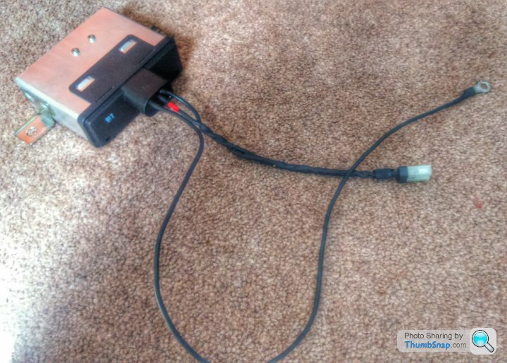
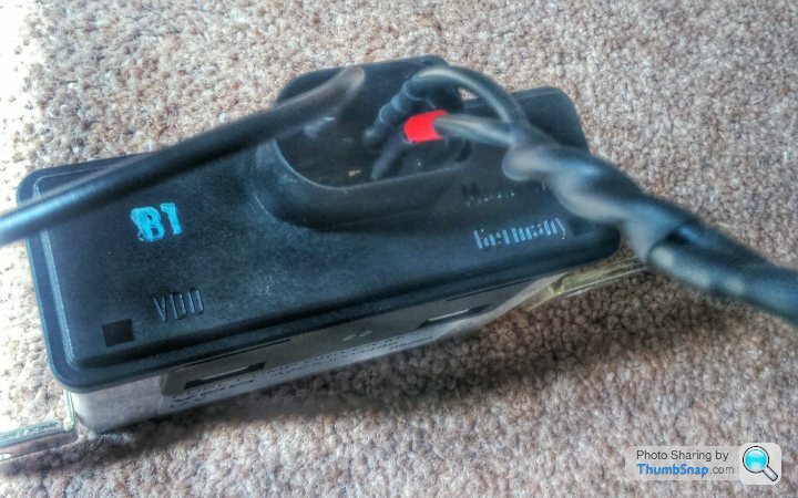
Pin 3 will be part of the engine loom, which I am still measuring up for.
Pin 5 I will take from an unused ign switched live from the standard Lotus loom, once I've finished paring out all the unnecessary wiring.
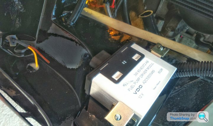
Unit mounted to the car
"Does anyone have info on available makes of Fuel Pump speed controllers?"
After 5 years and 14 pages, Steve D's original question is still unanswered. Those of us who are not engineers just want to buy something reasonably priced and good enough quality that will help our cars work better. Things have moved on since 2010, so what are users current opinions and experiences?
After 5 years and 14 pages, Steve D's original question is still unanswered. Those of us who are not engineers just want to buy something reasonably priced and good enough quality that will help our cars work better. Things have moved on since 2010, so what are users current opinions and experiences?
JohnMcL said:
"Does anyone have info on available makes of Fuel Pump speed controllers?"
After 5 years and 14 pages, Steve D's original question is still unanswered. Those of us who are not engineers just want to buy something reasonably priced and good enough quality that will help our cars work better. Things have moved on since 2010, so what are users current opinions and experiences?
There are two issues still imo.After 5 years and 14 pages, Steve D's original question is still unanswered. Those of us who are not engineers just want to buy something reasonably priced and good enough quality that will help our cars work better. Things have moved on since 2010, so what are users current opinions and experiences?
1) Controlling fuel pressure, like controlling anything, requires some knowledge of the system to be controlled. A truely "plug and play" returnless fuel system controller simply doesn't exist, because every fuel system is different (in terms of aftermarket, where people are basically installing a collection of parts into a vehicle). This is the same as why "generic" boost controllers aren't very good, because they have to compromise to try to work with everything! So whilst the basic control laws for a fuel pressure control system are, well, pretty basic, the devil really is in the details, and those details require the controller to be properly calibrated, which requires the calibrator to posses enough systems knowledge to be able to optimise the system to a reasonable level.
2) The cost of "proper" hardware. Even in 2015, the power electronics to control upto 20A required for a fuel pump isn't cheap to buy, or cheap to develop. And because the market volume is so low, it's difficult (possibly impossible) to make any money on it. Most of the existing aftermarket hardware is frankly rubbish, and has been costed down to such a degree in an attempt to make money that it effectively is not worth using.
My generation 1 pressure control unit is going strong, running in my car and 2 friends cars, not missing a beat, but it currently simply isn't worth my time to develop a more mass market version. For about £50 on ebay, you can get the components (press reg, etc) to make a conventional system work, whereas a pump controller is going to be around £400 in low volume, and then you need to calibrate it, and if you need help to do that, that'll be another £400 (at least). If i knew i could sell say 100 units, then it could be worth it, but i suspect each of those users wants different spec, or to utilise a different control method etc so the work to develop that mythical "universal" controller rapidly expands!
The best bet, is use your GoogleFoo to try to understand the basics, then buy an OEM module (like up there^^^^) and drive it with a suitable output of an aftermarket ECU. That way, you are leveraging the cheap and robust OEM hardware.
stevieturbo said:
What do you need in order to make yours work better ?
ie where are the problems that a speed controller will rectify ?
In my case I have a pump large enough to support the 500hp engine which then is noisy when driving around town and puts so much fuel round the system that it very quickly gets too hot.ie where are the problems that a speed controller will rectify ?
Steve
^^^ Ditto.
Anyone have experience of the Fuelab electronic regulator and pump?
http://fuelab.com/products/performance/fuel-pressu...
http://fuelab.com/products/performance/prodigy-fue...
or
Weldon Racing controller?
http://www.weldonracing.com/product/23/14000_Fuel_...
Anyone have experience of the Fuelab electronic regulator and pump?
http://fuelab.com/products/performance/fuel-pressu...
http://fuelab.com/products/performance/prodigy-fue...
or
Weldon Racing controller?
http://www.weldonracing.com/product/23/14000_Fuel_...
Edited by JohnMcL on Saturday 8th August 11:24
Edited by JohnMcL on Saturday 8th August 11:26
Unfortunately all those links show is just how much "bull" surrounds this kind of thing!
"able to detect changes in demand before change in rail pressure is realized"
Which sounds good, but breaks the laws of physics. If it can actually do that, then it can also tell me what next weeks winning Lottery numbers are ;-)
What that regulator does is simply to measure the position (height off the seat) of the regulators fluid valve orifice. The PWM pump controller then reads that position and drives the fuel pump in such a fashion as to attempt to keep that height constant. This is fundamentally a good halfway house to minimising return flow, without getting into the much more complex controls work required for a full returnless system. But what it can't do is realise a change in flow BEFORE the pressure changes!!
For example, they say:
"Controls pump speed with PWM, pulse width modulation, @ over 12,000 Hz. This means the electrical current to the electric motor is interrupted over 12,000 times per second to reduce the RPM
Over 64 times the switching frequency compared to our competition"
Which immediately shows me that who ever wrote that has no idea how a PWM controller works, or that fundamental switching frequency is not proportional to pump or controller efficiency / capability!
(the unit does not interrupt current to the motor, it interrupts voltage! The current flow is maintained by the pump motors inductance (V = L x dI/dT).
As such, 12Khz (64x faster that competitors!) is irrelevant, when a typical electric fuel pump has enough inductance to turn a 150Hz square wave into very nearly pure DC current flow (and hence motor torque). In fact, in this case, running (unnecessarily fast) at 12Khz results in lower efficiency, as the power silicon (MOSFET) switching & deadtime becomes a bigger proportion on the cycle.
"High efficiency sling vane positive displacement pump"
&
"Special housing shape for extremely quite operation and steady pressure"
Again, minor points, but sling vane pumps aren't that efficient, as the friction between the vane and housing is dependent on speed and pressure drop. So yeah, it might be a high efficiency sling vane pump but that doesn't make it a high efficiency pump. And, basic spelling errors are not really a good sign of professionalism eh!
Also, if this pump is as good as is claimed, how come they don't publish performance curves for it? If you go to BOSCH to buy a pump, they give you a datasheet that specifies it's performance.....
So, in summary, whilst i have no reason to suggest that those products listed don't work, i'm certainly suspicious by the veneer of "bull" that seems to have been glossed over the top of them.
JohnMcL said:
Anyone have experience of the Fuelab electronic regulator and pump?
http://fuelab.com/products/performance/fuel-pressu...
For example, they say:http://fuelab.com/products/performance/fuel-pressu...
"able to detect changes in demand before change in rail pressure is realized"
Which sounds good, but breaks the laws of physics. If it can actually do that, then it can also tell me what next weeks winning Lottery numbers are ;-)
What that regulator does is simply to measure the position (height off the seat) of the regulators fluid valve orifice. The PWM pump controller then reads that position and drives the fuel pump in such a fashion as to attempt to keep that height constant. This is fundamentally a good halfway house to minimising return flow, without getting into the much more complex controls work required for a full returnless system. But what it can't do is realise a change in flow BEFORE the pressure changes!!
JohnMcL said:
Weldon Racing controller?
http://www.weldonracing.com/product/23/14000_Fuel_...
If we ignore the fact that this controller looks like a right bodge from about 1987(unsealed screw terminals, through-hole components, strange enclosure etc etc), then we have no reason to think it doesn't work, at least in principal. But again, they let marketing get in the way of truth.http://www.weldonracing.com/product/23/14000_Fuel_...
For example, they say:
"Controls pump speed with PWM, pulse width modulation, @ over 12,000 Hz. This means the electrical current to the electric motor is interrupted over 12,000 times per second to reduce the RPM
Over 64 times the switching frequency compared to our competition"
Which immediately shows me that who ever wrote that has no idea how a PWM controller works, or that fundamental switching frequency is not proportional to pump or controller efficiency / capability!
(the unit does not interrupt current to the motor, it interrupts voltage! The current flow is maintained by the pump motors inductance (V = L x dI/dT).
As such, 12Khz (64x faster that competitors!) is irrelevant, when a typical electric fuel pump has enough inductance to turn a 150Hz square wave into very nearly pure DC current flow (and hence motor torque). In fact, in this case, running (unnecessarily fast) at 12Khz results in lower efficiency, as the power silicon (MOSFET) switching & deadtime becomes a bigger proportion on the cycle.
JohnMcL said:
They say:"High efficiency sling vane positive displacement pump"
&
"Special housing shape for extremely quite operation and steady pressure"
Again, minor points, but sling vane pumps aren't that efficient, as the friction between the vane and housing is dependent on speed and pressure drop. So yeah, it might be a high efficiency sling vane pump but that doesn't make it a high efficiency pump. And, basic spelling errors are not really a good sign of professionalism eh!
Also, if this pump is as good as is claimed, how come they don't publish performance curves for it? If you go to BOSCH to buy a pump, they give you a datasheet that specifies it's performance.....
So, in summary, whilst i have no reason to suggest that those products listed don't work, i'm certainly suspicious by the veneer of "bull" that seems to have been glossed over the top of them.
Gassing Station | Engines & Drivetrain | Top of Page | What's New | My Stuff