Testing sensor on R1
Discussion


So this morning I get a code '11' error flashing on the dashboard... the engine management light on and the bike turns over but will not start.
Consulted manual and get:
No normal signals are received from the cylinder identification sensor.
Probable causes:
Open/short circuit in wiring subharness
Open/short circuit in wiring harness
Defective cylinder identification sensor
Malfunction in ECU
Improperly installed sensor
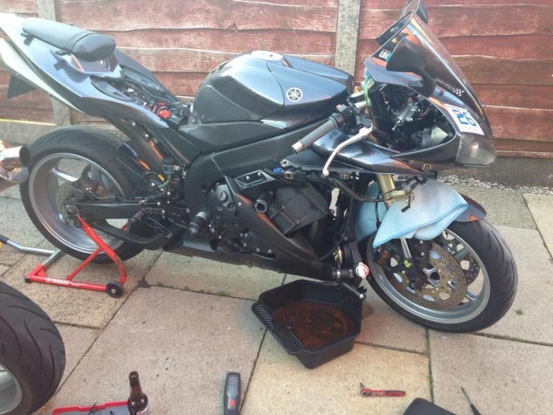
So I've checked all the fuses and they seem fine... I have checked the wiring to / from the CIS ... all looks fine to me (I removed the rad to get a proper look) ....
So next step is to test the voltage at the plug... factory manual states:
On: 4.8 v >
Off: 0.8v <
Checking will my old multimeter I get:
On: 4.5v
Off: 0.25v
Close enough? Bit worried the 'On' figure is slightly lower than factory manual states ... 0.3v ?
What do people think? - I'm wondering if I somehow tested the voltage wrong or perhaps my multimeter is a little out?
Proper PITA to get to the CIS...
Consulted manual and get:
No normal signals are received from the cylinder identification sensor.
Probable causes:
Open/short circuit in wiring subharness
Open/short circuit in wiring harness
Defective cylinder identification sensor
Malfunction in ECU
Improperly installed sensor
So I've checked all the fuses and they seem fine... I have checked the wiring to / from the CIS ... all looks fine to me (I removed the rad to get a proper look) ....
So next step is to test the voltage at the plug... factory manual states:
On: 4.8 v >
Off: 0.8v <
Checking will my old multimeter I get:
On: 4.5v
Off: 0.25v
Close enough? Bit worried the 'On' figure is slightly lower than factory manual states ... 0.3v ?
What do people think? - I'm wondering if I somehow tested the voltage wrong or perhaps my multimeter is a little out?
Proper PITA to get to the CIS...

Easiest and cheapest option is to change the sensor.
What kind of multi meter do you have? Digital or analogue? Cheapie or decent like Fluke?
However, where you measure the voltage, is this from the ECU? Is it with the CIS connected and what do you mean on/off? Is that the change when cranking?
Ifit's the trigger signal returned from the sensor when cranking then again i would suspect the CIS.
bass gt3 said:
Easiest and cheapest option is to change the sensor.
What kind of multi meter do you have? Digital or analogue? Cheapie or decent like Fluke?
However, where you measure the voltage, is this from the ECU? Is it with the CIS connected and what do you mean on/off? Is that the change when cranking?
Ifit's the trigger signal returned from the sensor when cranking then again i would suspect the CIS.
My thoughts also... so got a new sensor arriving tomorrow.What kind of multi meter do you have? Digital or analogue? Cheapie or decent like Fluke?
However, where you measure the voltage, is this from the ECU? Is it with the CIS connected and what do you mean on/off? Is that the change when cranking?
Ifit's the trigger signal returned from the sensor when cranking then again i would suspect the CIS.
It's a digital multimeter... cheapo Gunsons thing...
I measured at the plug that connects to the sensor without the CIS connected.
On - ignition on
Off - ignition off
Yes, it is the trigger signal - apparently only used for start-up IIRC?

Mr OCD said:
My thoughts also... so got a new sensor arriving tomorrow.
It's a digital multimeter... cheapo Gunsons thing...
I measured at the plug that connects to the sensor without the CIS connected.
On - ignition on
Off - ignition off
Yes, it is the trigger signal - apparently only used for start-up IIRC?
Thanks for posting the manual.It's a digital multimeter... cheapo Gunsons thing...
I measured at the plug that connects to the sensor without the CIS connected.
On - ignition on
Off - ignition off
Yes, it is the trigger signal - apparently only used for start-up IIRC?
Ok, the CIS is a Hall Effect sensor that triggers off a toothed wheel to signal where in the engine rotation the crank is. The ecu then times all ignition and fuelling from this signal.
The sensor has 3 wires to it. +5v feed, signal back to ecu and ground. The reference in the book states that the signal should be greater than 4.8 vdc when the sensor is high and less than 0.8vdc low. These are the trigger states. The ECU looks for this wave signal and then runs from that. The fact you're at 4.5vdc says the sensor is poked. This means rather than measuring with the ignition off or on, it's refering to when the sensor is on or off, ie, is it adjacent a tooth or not? So the signal to the ecu goes 4.8vdc (min) to <0.8vdc for the ecu to accept the signal and begin timing the engine.If the signal doesn't meet these criteria, the engine spins and no synchronisation happens,hence no broom broom!!
 Then it throws an error code and here you a are.
Very simple fix and fair play to Yam for what seems a decent check warning system.
And FYI, the ecu uses the CIS ALL the time, not just for starting. It's the basic sync signal for the ecu, and depending on the type off system you may have one on the cam as well. The crank goes 720 degees while the cam goes 360 in one cycle so some systems time when the valves open to fire the injectors and spark whereas many fire on both the power and exhaust strokes.
Edited by bass gt3 on Friday 25th July 12:38
bass gt3 said:
Thanks for posting the manual.
Ok, the CIS is a Hall Effect sensor that triggers off a toothed wheel to signal where in the engine rotation the crank is. The ecu then times all ignition and fuelling from this signal.
The sensor has 3 wires to it. +5v feed, signal back to ecu and ground. The reference in the book states that the signal should be greater than 4.8 nvdc when the sensor is high and less than 0.8vdc low. These are the trigger states. The ECU looks for this wave signal and then runs from that. The fact you're at 4.5vdc says the sensor is poked. This means rather than measuring with the ignition off or on, it's when the sensor is on or off, ie, is it adjacent a tooth or not? So the signal to the ecu goes 4.8vdc (min) to <0.8vdc for the ecu to accept the signal and begin timing the engine.
And FYI, the ecu uses the CIS ALL the time, not just for starting. It's the basic sync signal for the ecu, and depending on the type off system you may have one on the cam as well. The crank goes 720 degees while the cam goes 360 in one cycle.
Well I've learned something today. Thank you Sir - Much appreciated. Now I understand why the values defer from the book Ok, the CIS is a Hall Effect sensor that triggers off a toothed wheel to signal where in the engine rotation the crank is. The ecu then times all ignition and fuelling from this signal.
The sensor has 3 wires to it. +5v feed, signal back to ecu and ground. The reference in the book states that the signal should be greater than 4.8 nvdc when the sensor is high and less than 0.8vdc low. These are the trigger states. The ECU looks for this wave signal and then runs from that. The fact you're at 4.5vdc says the sensor is poked. This means rather than measuring with the ignition off or on, it's when the sensor is on or off, ie, is it adjacent a tooth or not? So the signal to the ecu goes 4.8vdc (min) to <0.8vdc for the ecu to accept the signal and begin timing the engine.
And FYI, the ecu uses the CIS ALL the time, not just for starting. It's the basic sync signal for the ecu, and depending on the type off system you may have one on the cam as well. The crank goes 720 degees while the cam goes 360 in one cycle.
Edited by bass gt3 on Friday 25th July 12:27
Sensor here tomorrow ...


bass gt3 said:
Thanks for posting the manual.
Ok, the CIS is a Hall Effect sensor that triggers off a toothed wheel to signal where in the engine rotation the crank is. The ecu then times all ignition and fuelling from this signal.
You seem to be describing a crank position sensor, which only tells you the position of the crankshaft. A cylinder identification sensor would have to work off a camshaft so it can determine the difference between TDC compression and TDC exhaust (which a crank sensor alone doesn't tell you). This would theoretically only been needed at start up, because once the crank/cam phase has been determined the ECU can then track it without the cam sensor.Ok, the CIS is a Hall Effect sensor that triggers off a toothed wheel to signal where in the engine rotation the crank is. The ecu then times all ignition and fuelling from this signal.
Mr OCD: The manual is not suggesting you measure the sensor voltage with the ignition on and off. You are checking it's working by measuring the sensor output voltage (with ignition on) whilst the sensor is activated by the cam shaft, and then again with the sensor de-activated (i.e. turn the engine over to ensure the output of the sensor is changing states and measure the voltage in both states).
Edited by Mr2Mike on Saturday 26th July 20:37
Mr2Mike said:
You seem to be describing a crank position sensor, which only tells you the position of the crankshaft. A cylinder identification sensor would have to work off a camshaft so it can determine the difference between TDC compression and TDC exhaust (which a crank sensor alone doesn't tell you). This would theoretically only been needed at start up, because once the crank/cam phase has been determined the ECU can then track it without the cam sensor.
Mr OCD: The manual is not suggesting you measure the sensor voltage with the ignition on and off. You are checking it's working by measuring the sensor output voltage (with ignition on) whilst the sensor is activated by the cam shaft, and then again with the sensor de-activated (i.e. turn the engine over to ensure the output of the sensor is changing states and measure the voltage in both states).
Thanks for that... good to know Mr OCD: The manual is not suggesting you measure the sensor voltage with the ignition on and off. You are checking it's working by measuring the sensor output voltage (with ignition on) whilst the sensor is activated by the cam shaft, and then again with the sensor de-activated (i.e. turn the engine over to ensure the output of the sensor is changing states and measure the voltage in both states).
Edited by Mr2Mike on Saturday 26th July 20:37
First time ridden this morning since the new sensor and it is MUCH smoother... very odd.
Hooli said:
I bet it's dodgy for a while. Took me ages to find a dodgy TPS the other year, changing that made my bike seem strangely smooth too.
Funny thing is I noticed after the recent track day it felt a bit vibey and put it down to the sprocket change and was considering changing back to stock (just for BN) gearing ... seems fine since the CI sensor been changed which is even weirder as according to above it should only be used at start up?Mr OCD said:
Hooli said:
I bet it's dodgy for a while. Took me ages to find a dodgy TPS the other year, changing that made my bike seem strangely smooth too.
Funny thing is I noticed after the recent track day it felt a bit vibey and put it down to the sprocket change and was considering changing back to stock (just for BN) gearing ... seems fine since the CI sensor been changed which is even weirder as according to above it should only be used at start up?Hooli said:
According to Bass up there ^^^ the ECU uses it all the time. My assumption would be that a high or low reading would trigger the ECU at the wrong time which would screw up your timing for both spark & injection.
Indeed.There's no condition at start up that would rquire a dedicated sensor for that initial 3-4 seconds and then switch timing toaseperate sensor. Everything the ECU needs can be derived from either a cam OR crank sensor.
If the sensor was starting to fail, it could be sending asignalback to the ECU thats the wrong amplitude, has excessiveinterference/noise or hasexcessive latency.Any of thesedegradations would cause the ECU to run out of kilter and affect the enginesrunning or performance.
Remember that manufacturers don't over complicate things,especially when it costs more. Seeing as the R1 hasn't got VTec,the need to a cam AND crank sensor doesn't exist. If it runs batch fire, a crank signal is fine. Sequential or batch and a camsignal will suffice.
Remember that on a FI system, ANY sensor starting to fail will have a detrimental effect. TPS obviously, but even a faulty temp sensor cam mimica coldengine and keep the ECU running with cold enrichment (Choke) on when it shouldn't be.
But just for your sanity,with the bikeat tickover, disconnect the CIS. Pound to a penny the motor stops dead.
bass gt3 said:
Indeed.
There's no condition at start up that would rquire a dedicated sensor for that initial 3-4 seconds and then switch timing toaseperate sensor. Everything the ECU needs can be derived from either a cam OR crank sensor.
If the sensor was starting to fail, it could be sending asignalback to the ECU thats the wrong amplitude, has excessiveinterference/noise or hasexcessive latency.Any of thesedegradations would cause the ECU to run out of kilter and affect the enginesrunning or performance.
Remember that manufacturers don't over complicate things,especially when it costs more. Seeing as the R1 hasn't got VTec,the need to a cam AND crank sensor doesn't exist. If it runs batch fire, a crank signal is fine. Sequential or batch and a camsignal will suffice.
Remember that on a FI system, ANY sensor starting to fail will have a detrimental effect. TPS obviously, but even a faulty temp sensor cam mimica coldengine and keep the ECU running with cold enrichment (Choke) on when it shouldn't be.
But just for your sanity,with the bikeat tickover, disconnect the CIS. Pound to a penny the motor stops dead.

If you had told me that over the weekend I would have tested it ...
 ... it was a proper t
 t to get at as well despite only being held in with one bolt
 Edited by Mr OCD on Monday 28th July 16:00
Gassing Station | Biker Banter | Top of Page | What's New | My Stuff