clutch master cylinder access panel
Discussion


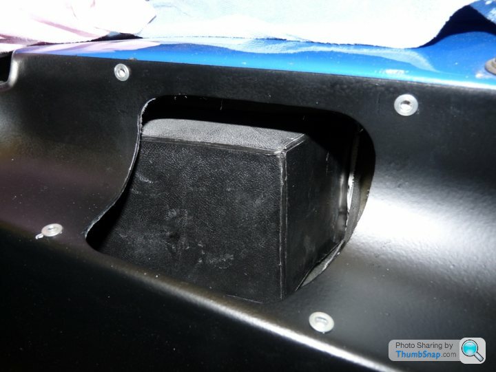
Held on by copious amounts of silicon and a handful of self tappers, the clutch cover isnt one of TVR's finest designs. I modified my clutch cover when I had the engine out of my Griffith last year.
The original cover started off like this - its what was left of the original cover once the loose fibreglass was removed.
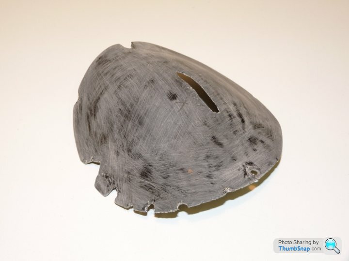
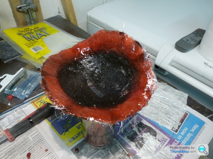
I then started to thicken the base of the cover to make it sit further off the inner wing and to create a bit of a gap between it and the master cylinder cap. The previous photo shows a slit in the middle of the cover which I think originated from a stress fracture caused by the clutch cover being forced over the master cylinder cap when it was screwed down in place. The photo below shows the first couple of layers of fibreglass being added to the base of the cover.
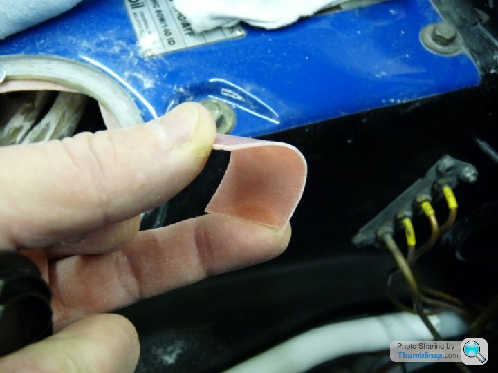
I found that the rough files used to file ceramic tiles are excellent for rough forming in fibreglass. After much glassfibring and filing/sanding, I ended up with this
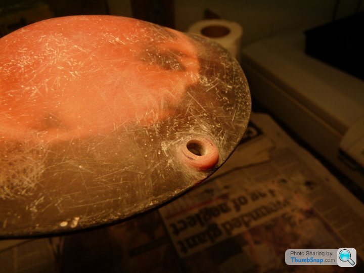
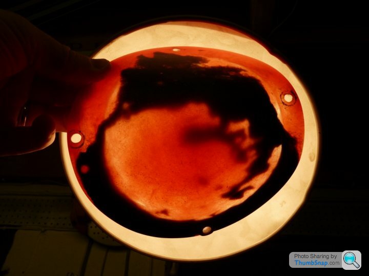
Which is the same as the cover in the photo below. This was taken with the cover held in front of a spotlight. The black patches are all thats left of the original cover.
I needed to add material to the hole in the inner wing so that I would have something to screw the clutch cover to. I started by making up some thin, flat, flexible pieces of fibreglass. I seem to recall using the inside of a large baking tray to form these.
These flexible strips were then self tappered to the inner wing. These were used to provide a stable platform on which to build up a number of layers of fibreglass. Without some form of base, the fibreglass would have just sagged and disappeared into the inner wing.


Once sufficient layers had been built up and filed smooth I ended up with this

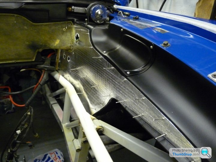
Then I drilled and inserted rivnut fasteners so that I could bolt the cover on and get it back off again. The whole lot was then painted black. The photo below also shows the new inner wing heat shielding that I was also in the process or making up.

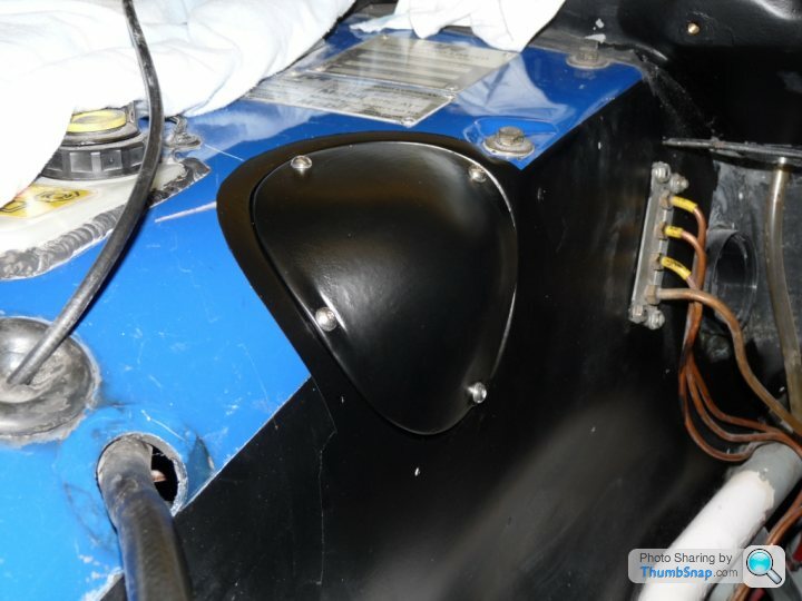
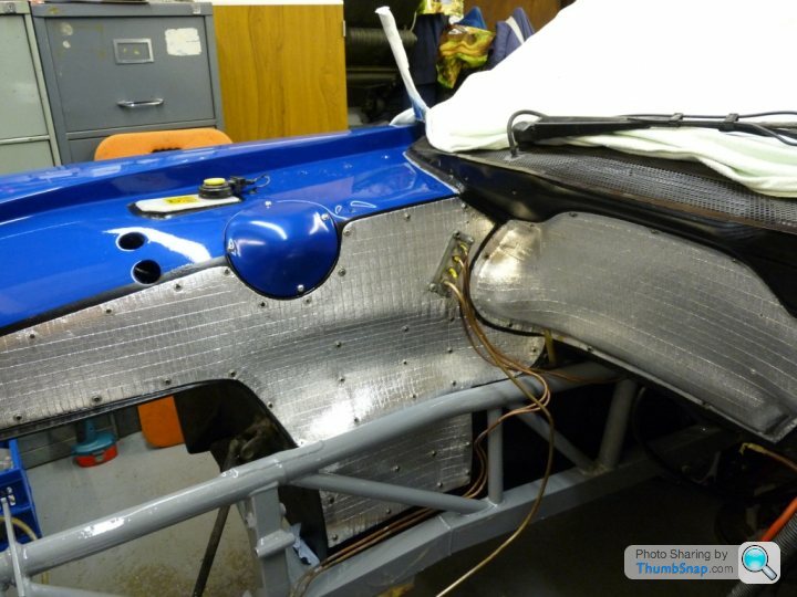
After looking at this for a while I decided I didnt like the black border round the clutch cover. I had painted this to hide some scratches in the paintwork which were there from , I guess, previous attempts to remove the clutch cover. I eventually ended up repainting both inner wings as well as the clutch cover as below
This photo shows the cover as well as the completed heat shield matting.
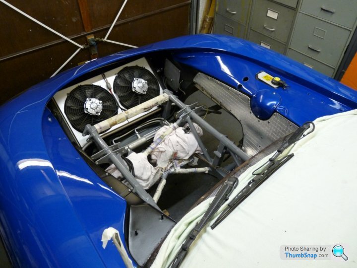
...and another during the engine reinstallation

After putting in quite a lot of work on this I didnt want it to end up looking like a six year old had got hold of the silicon gun and had pretended to ice a cake. In order to waterproof the cover and avoid unsightly amounts of silicon being visible, I put a bead of silicon round the clutch cover and allowed it to cure completely over a few days. I also applied a bead of silicon to the mating face on the inner wing and also let that cure completely. Then the cover was simply bolted to the inner wing. I've checked in the drivers footwell on a number of occassions since Ive had the car back on the road but there is no evidence of water ingress, so it looks like the waterproofing has been successful.
I've also modified the fuse box cover that is located beneath the intake pipe to take rivnut fasteners as well.
Hope this helps
Cheers
Marty
The original cover started off like this - its what was left of the original cover once the loose fibreglass was removed.
I then started to thicken the base of the cover to make it sit further off the inner wing and to create a bit of a gap between it and the master cylinder cap. The previous photo shows a slit in the middle of the cover which I think originated from a stress fracture caused by the clutch cover being forced over the master cylinder cap when it was screwed down in place. The photo below shows the first couple of layers of fibreglass being added to the base of the cover.
I found that the rough files used to file ceramic tiles are excellent for rough forming in fibreglass. After much glassfibring and filing/sanding, I ended up with this
Which is the same as the cover in the photo below. This was taken with the cover held in front of a spotlight. The black patches are all thats left of the original cover.
I needed to add material to the hole in the inner wing so that I would have something to screw the clutch cover to. I started by making up some thin, flat, flexible pieces of fibreglass. I seem to recall using the inside of a large baking tray to form these.
These flexible strips were then self tappered to the inner wing. These were used to provide a stable platform on which to build up a number of layers of fibreglass. Without some form of base, the fibreglass would have just sagged and disappeared into the inner wing.
Once sufficient layers had been built up and filed smooth I ended up with this
Then I drilled and inserted rivnut fasteners so that I could bolt the cover on and get it back off again. The whole lot was then painted black. The photo below also shows the new inner wing heat shielding that I was also in the process or making up.
After looking at this for a while I decided I didnt like the black border round the clutch cover. I had painted this to hide some scratches in the paintwork which were there from , I guess, previous attempts to remove the clutch cover. I eventually ended up repainting both inner wings as well as the clutch cover as below
This photo shows the cover as well as the completed heat shield matting.
...and another during the engine reinstallation
After putting in quite a lot of work on this I didnt want it to end up looking like a six year old had got hold of the silicon gun and had pretended to ice a cake. In order to waterproof the cover and avoid unsightly amounts of silicon being visible, I put a bead of silicon round the clutch cover and allowed it to cure completely over a few days. I also applied a bead of silicon to the mating face on the inner wing and also let that cure completely. Then the cover was simply bolted to the inner wing. I've checked in the drivers footwell on a number of occassions since Ive had the car back on the road but there is no evidence of water ingress, so it looks like the waterproofing has been successful.
I've also modified the fuse box cover that is located beneath the intake pipe to take rivnut fasteners as well.
Hope this helps
Cheers
Marty
Edited by Marty V8 on Wednesday 25th April 01:10

Thats a work of art but for a quick job is to use some edging ,i had some spare from the windscreen sill.
The secret is to use the right silicone ,i can rub mine off the inner wing and cover with my fingers in a few minutes ,you want a low mod black silicone .I used some very low mod gutter silicone .Its allso pulls off in one go ,worst thing you could do is use sikaflex

The secret is to use the right silicone ,i can rub mine off the inner wing and cover with my fingers in a few minutes ,you want a low mod black silicone .I used some very low mod gutter silicone .Its allso pulls off in one go ,worst thing you could do is use sikaflex

SILICONEKID340HP said:
Thats a work of art but for a quick job is to use some edging ,i had some spare from the windscreen sill.
The secret is to use the right silicone ,i can rub mine off the inner wing and cover with my fingers in a few minutes ,you want a low mod black silicone .I used some very low mod gutter silicone .Its allso pulls off in one go ,worst thing you could do is use sikaflex
Good point Daz, high modulus is a lot more permanent The secret is to use the right silicone ,i can rub mine off the inner wing and cover with my fingers in a few minutes ,you want a low mod black silicone .I used some very low mod gutter silicone .Its allso pulls off in one go ,worst thing you could do is use sikaflex
 never knew you was so knowledgeable about silicone sealants
  have you had much experience of the stuff before then? .
Simon says said:
SILICONEKID340HP said:
Thats a work of art but for a quick job is to use some edging ,i had some spare from the windscreen sill.
The secret is to use the right silicone ,i can rub mine off the inner wing and cover with my fingers in a few minutes ,you want a low mod black silicone .I used some very low mod gutter silicone .Its allso pulls off in one go ,worst thing you could do is use sikaflex
Good point Daz, high modulus is a lot more permanent The secret is to use the right silicone ,i can rub mine off the inner wing and cover with my fingers in a few minutes ,you want a low mod black silicone .I used some very low mod gutter silicone .Its allso pulls off in one go ,worst thing you could do is use sikaflex
never knew you was so knowledgeable about silicone sealants have you had much experience of the stuff before then? . 
This is the type of stuff you need
http://www.ebay.co.uk/itm/Low-Modulus-Neutral-Cure...
Edited by SILICONEKID340HP on Wednesday 25th April 21:01

 I was kidding, i have been knocking around a long time on these forums Daz
  thanks for the link
 Good tip from Daz re the low modulus silicon and the edging. I didnt have any other realistic option other than to re-make my cover as there wasnt much of it left, and what there was, was getting somewhat flaky. The self tappers weren't really holding much  it was the silicon that was doing most of the work.
The beauty of it was that if I had made a complete b@lls up of it, I could have thrown it away and probably got a half decent one from a TVR breakers somewhere. Give it a go. its quite thereputic
it was the silicon that was doing most of the work.The beauty of it was that if I had made a complete b@lls up of it, I could have thrown it away and probably got a half decent one from a TVR breakers somewhere. Give it a go. its quite thereputic
Simon says said:
Tidy job Marty V8  Rivnuts are wonderful things
They do look pretty handy! I'd never heard of them before, thanks! Which type is best for fibreglass though? Aluminium, steel, splined - so much choice! Rivnuts are wonderful things Maybe these:
http://www.spaldingfasteners.co.uk/index.php?optio...
OP - cracking job. My cover is off and painted body colour ready to go back on, but I'm inspired! I'm jost off to the garage, I may be a while ...
Edited by VictorMeldrew on Thursday 26th April 09:03
VictorMeldrew said:
Simon says said:
Tidy job Marty V8 Rivnuts are wonderful things
They do look pretty handy! I'd never heard of them before, thanks! Which type is best for fibreglass though? Aluminium, steel, splined - so much choice! Rivnuts are wonderful things Maybe these:
http://www.spaldingfasteners.co.uk/index.php?optio...
OP - cracking job. My cover is off and painted body colour ready to go back on, but I'm inspired! I'm jost off to the garage, I may be a while ...
Edited by VictorMeldrew on Thursday 26th April 09:03

VictorMeldrew said:
They do look pretty handy! I'd never heard of them before, thanks! Which type is best for fibreglass though? Aluminium, steel, splined - so much choice!
Nice job these little chaps are handy,and no special tools required

Simon says said:
ell I prefer the steel splined ones from Wurth but only because I have there tool and Rivnuts, I have used the alloy non-splined with success on the TVR though especially the smaller jobs i.e when I moved the rad expansion bottle
I also used steel rivnuts for the same reason - they were all I had. In order to prevent the rivnut possibly cracking the fibreglass as they were installed, I put a washer behind each one to spread the load.Marty V8 said:
Simon says said:
ell I prefer the steel splined ones from Wurth but only because I have there tool and Rivnuts, I have used the alloy non-splined with success on the TVR though especially the smaller jobs i.e when I moved the rad expansion bottle
I also used steel rivnuts for the same reason - they were all I had. In order to prevent the rivnut possibly cracking the fibreglass as they were installed, I put a washer behind each one to spread the load.Gassing Station | Chimaera | Top of Page | What's New | My Stuff