Converting to Megasquirt
Discussion


https://www.merlinmotorsport.co.uk/p/jetex-lambda-...
M12 x 1.25 caphead setscrews from your local nut and bolt place or ebay plus a copper washer to bung the narrowband bosses. I had to cut down the ones shown as shortest I could get at the time was 30mm.
[url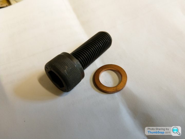 |https://thumbsnap.com/GXwQSR5z[/url]
Dougal.
M12 x 1.25 caphead setscrews from your local nut and bolt place or ebay plus a copper washer to bung the narrowband bosses. I had to cut down the ones shown as shortest I could get at the time was 30mm.
[url
|https://thumbsnap.com/GXwQSR5z[/url]Dougal.
Where you place your wideband sensor is critical, while it may seem intuitive to place it in the 'Y' where the gasses from each bank merge..... I'd strongly recommend you actually move it a good 10" further downstream in the exhaust system.
Exhaust gasses at the 'Y' piece where they merge can be very turbulent, so for a much more stable AFR reading its advisable to move your Lambda sensor further down the exhaust system where the gas flow and bank to bank mix has become more consistent. Also take great care to ensure there are no air leaks in the system before the sensor as this will also give you false and unstable readings, exhaust manifold leaks and ill fitting band clamps at the 'Y' must be addressed.
You will need a nice clean 360 degree bead of weld around your threaded sensor collar so it won't draw air there either, and finally it should be fitted so when you screw your sensor in its facing slightly down so condensation will not collect on its tip.
ChimpOnGas said:
Where you place your wideband sensor is critical, while it may seem intuitive to place it in the 'Y' where the gasses from each bank merge..... I'd strongly recommend you actually move it a good 10" further downstream in the exhaust system.
Exhaust gasses at the 'Y' piece where they merge can be very turbulent, so for a much more stable AFR reading its advisable to move your Lambda sensor further down the exhaust system where the gas flow and bank to bank mix has become more consistent. Also take great care to ensure there are no air leaks in the system before the sensor as this will also give you false and unstable readings, exhaust manifold leaks and ill fitting band clamps at the 'Y' must be addressed.
You will need a nice clean 360 degree bead of weld around your threaded sensor collar so it won't draw air there either, and finally it should be fitted so when you screw your sensor in its facing slightly down so condensation will not collect on its tip.
Good advice thanks. So place it closer to the y piece to exhaust clamp area section of pipe?Exhaust gasses at the 'Y' piece where they merge can be very turbulent, so for a much more stable AFR reading its advisable to move your Lambda sensor further down the exhaust system where the gas flow and bank to bank mix has become more consistent. Also take great care to ensure there are no air leaks in the system before the sensor as this will also give you false and unstable readings, exhaust manifold leaks and ill fitting band clamps at the 'Y' must be addressed.
You will need a nice clean 360 degree bead of weld around your threaded sensor collar so it won't draw air there either, and finally it should be fitted so when you screw your sensor in its facing slightly down so condensation will not collect on its tip.
Belle427 said:
ChimpOnGas said:
Where you place your wideband sensor is critical, while it may seem intuitive to place it in the 'Y' where the gasses from each bank merge..... I'd strongly recommend you actually move it a good 10" further downstream in the exhaust system.
Exhaust gasses at the 'Y' piece where they merge can be very turbulent, so for a much more stable AFR reading its advisable to move your Lambda sensor further down the exhaust system where the gas flow and bank to bank mix has become more consistent. Also take great care to ensure there are no air leaks in the system before the sensor as this will also give you false and unstable readings, exhaust manifold leaks and ill fitting band clamps at the 'Y' must be addressed.
You will need a nice clean 360 degree bead of weld around your threaded sensor collar so it won't draw air there either, and finally it should be fitted so when you screw your sensor in its facing slightly down so condensation will not collect on its tip.
Good advice thanks. So place it closer to the y piece to exhaust clamp area section of pipe?Exhaust gasses at the 'Y' piece where they merge can be very turbulent, so for a much more stable AFR reading its advisable to move your Lambda sensor further down the exhaust system where the gas flow and bank to bank mix has become more consistent. Also take great care to ensure there are no air leaks in the system before the sensor as this will also give you false and unstable readings, exhaust manifold leaks and ill fitting band clamps at the 'Y' must be addressed.
You will need a nice clean 360 degree bead of weld around your threaded sensor collar so it won't draw air there either, and finally it should be fitted so when you screw your sensor in its facing slightly down so condensation will not collect on its tip.


 |https://thumbsnap.com/alMtbK9T[/url]
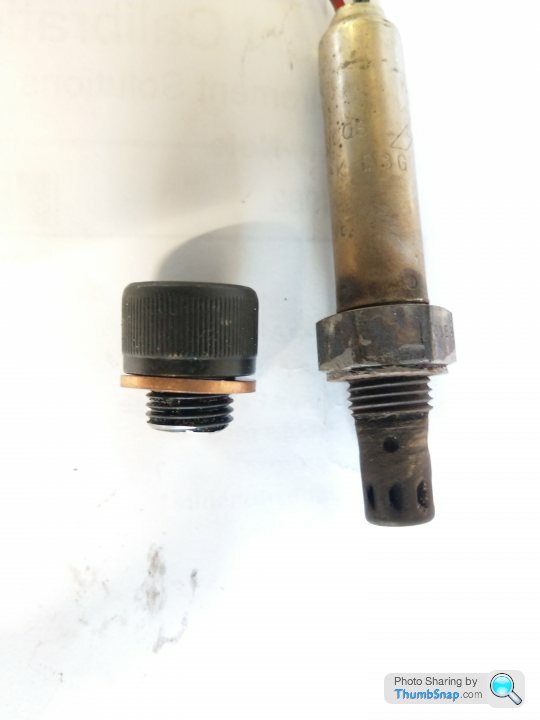

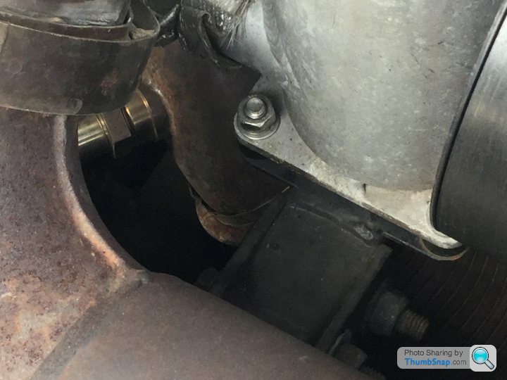
 Must remember to fit that missing bolt.
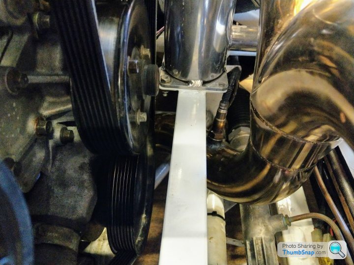

ChimpOnGas said:
Ironically, this is where my sensor was fitted.

It would clearly benefit from relocation further down the system
I don't see anything wrong with a sensor there, sensors are often fitted in areas of high turbulence, makes no odds from what I've seen.It would clearly benefit from relocation further down the system
However ... I do fit the sensors on the down pipe but more for aesthetic reasons than anything else .. a sensor positioned as in your pic looks unsightly, but I don't see why it should affect its operation. In fact, the shorter the distance to the engine the faster the sensor sees any mixture changes, so the more reliable any fuelling trimming might be, especially at light throttle/low exhaust gas flow times.


spitfire4v8 said:
I don't see anything wrong with a sensor there, sensors are often fitted in areas of high turbulence, makes no odds from what I've seen.
However ... I do fit the sensors on the down pipe but more for aesthetic reasons than anything else .. a sensor positioned as in your pic looks unsightly, but I don't see why it should affect its operation. In fact, the shorter the distance to the engine the faster the sensor sees any mixture changes, so the more reliable any fuelling trimming might be, especially at light throttle/low exhaust gas flow times.
I have both places fitted with bungs but settled for between the banks as shown , like mentioned turbulence makes no difference its an 02 sniffer , I settled for the top position for nothing more than neatness with the loom and accessibility to the sensor , like I say tried both However ... I do fit the sensors on the down pipe but more for aesthetic reasons than anything else .. a sensor positioned as in your pic looks unsightly, but I don't see why it should affect its operation. In fact, the shorter the distance to the engine the faster the sensor sees any mixture changes, so the more reliable any fuelling trimming might be, especially at light throttle/low exhaust gas flow times.
 two positions is useful to cross ref one WB controller to another just to make sure accuracy dont start to wander not essential however
Edited by Sardonicus on Tuesday 4th June 13:16
Sardonicus said:
spitfire4v8 said:
I don't see anything wrong with a sensor there, sensors are often fitted in areas of high turbulence, makes no odds from what I've seen.
However ... I do fit the sensors on the down pipe but more for aesthetic reasons than anything else .. a sensor positioned as in your pic looks unsightly, but I don't see why it should affect its operation. In fact, the shorter the distance to the engine the faster the sensor sees any mixture changes, so the more reliable any fuelling trimming might be, especially at light throttle/low exhaust gas flow times.
I have both places fitted with bungs but settled for between the banks as shown , like mentioned turbulence makes no difference its an 02 sniffer , I settled for the top position for nothing more than neatness with the loom and accessibility to the sensor , like I say tried both However ... I do fit the sensors on the down pipe but more for aesthetic reasons than anything else .. a sensor positioned as in your pic looks unsightly, but I don't see why it should affect its operation. In fact, the shorter the distance to the engine the faster the sensor sees any mixture changes, so the more reliable any fuelling trimming might be, especially at light throttle/low exhaust gas flow times.
two positions is useful to cross ref one WB controller to another just to make sure accuracy dont start to wander not essential however Edited by Sardonicus on Tuesday 4th June 13:16
I was planning to move the sensor on the advice of a respected engine management engineer but happy to leave it where it is, the bottom line is my AFRs are not as stable as I'd like or in comparisons to other Chimaeras I've seen with an AFR gauge, this may be more a function of my controller sensitivity (AEM X-Wifi) or it may be a voltage instability thing (see my voltage declines under acceleration post).
All I can say is I'd like to see the readings a bit more stable, it seems to me closed loop is going to have a really hard time keeping up with this instability, indeed the strategy may actually be counterproductive as the ECU will be constantly shooting for my target in response to big swings in AFR especially as I have slowed its check rate and correction percentage.
TBH I have my doubts the system can correct that fast anyway which is why I restricted its input.
Discuss

Gassing Station | Chimaera | Top of Page | What's New | My Stuff