J400 GED Chimaera Chassis refurb
Discussion


With the chassis out of the way, spent the last couple of days cleaning and painting. 
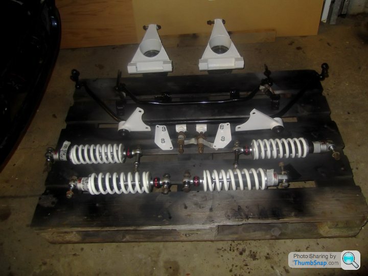
I also actually fitted some new bushes ready for the rebuild.
Next weekend's jobs are:
Replace the Diff nose seal.
Clean up and paint the driveshafts.
Re-pack the CV joints and fit new gaiters.
Then it's on to the engine and gearbox.
I also actually fitted some new bushes ready for the rebuild.
Next weekend's jobs are:
Replace the Diff nose seal.
Clean up and paint the driveshafts.
Re-pack the CV joints and fit new gaiters.
Then it's on to the engine and gearbox.
Today's jobs were replace the Diff nose (input) seal and paint the driveshafts ready for repacking and new gaiters.
First up the Diff nose seal.
Step 1: Mark the nut, shaft and propshaft flange - so you know where the nut should be tightened to on re-assembly.
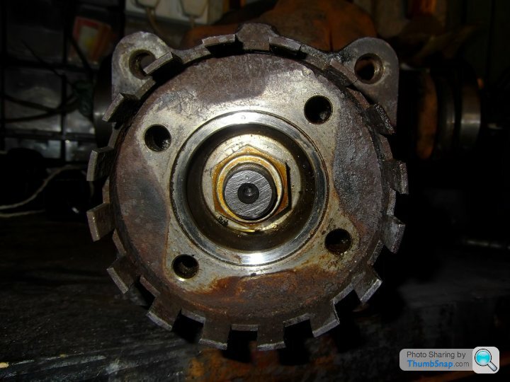
Step 2: As belt and braces, I also measured the distance from the front face of the input shaft to the front face of the nut as well as counting the number of threads visible.
Step 3: Mark up the socket with which you undo the nut - to make it easier to count the number of turns required to remove the nut.
Step 3: Remove the nut - IMPORTANT count the number of turns it requires to remove the nut and write it down.
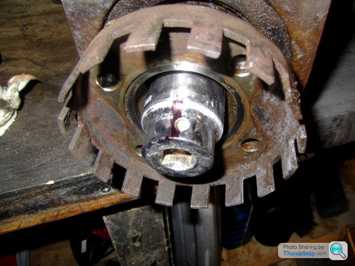
Step 4: Remove the driveshaft flange - mine came off easily, although I have heard tell of people requiring a puller to remove it.
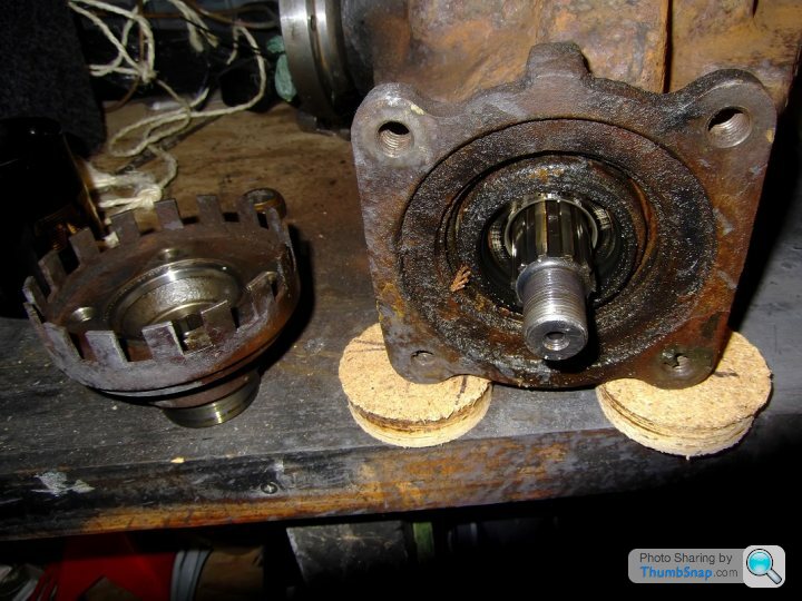
Step 5: Clean up the old seal as much as possible prior to removing it, to avoid any dirt getting into the diff.
Step 6: Remove the old seal, noting it's orientation ready for fitting the new seal.
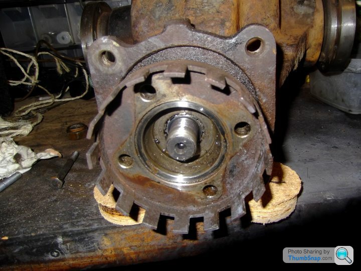
Step 7: Fit new seal. I gently tapped mine in using an old bearing outer race which sat nicely onto the new seal body (metal part, not the rubber part). I could tell when it was seated correctly as the sound of the hammer taps changed - you'll recognise it when you hear it.

Step 8: Refit the nut, counting the number of turns as you go. This is where the marks in step 1 come into play. Tighten the nut until the marks line up exactly as they were when you started, if you have done this with the correct number of turns then the load on the input shaft is the same as before.

Trust me, the marks do line up as before, it's an optical illusion because the pic was taken from a different angle.
Job done!
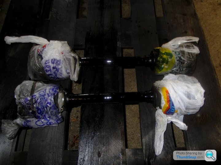
Then I painted the drive shafts ready for re-packing and new gaiters.
Now it's time to go to the Driving Range
First up the Diff nose seal.
Step 1: Mark the nut, shaft and propshaft flange - so you know where the nut should be tightened to on re-assembly.
Step 2: As belt and braces, I also measured the distance from the front face of the input shaft to the front face of the nut as well as counting the number of threads visible.
Step 3: Mark up the socket with which you undo the nut - to make it easier to count the number of turns required to remove the nut.
Step 3: Remove the nut - IMPORTANT count the number of turns it requires to remove the nut and write it down.
Step 4: Remove the driveshaft flange - mine came off easily, although I have heard tell of people requiring a puller to remove it.
Step 5: Clean up the old seal as much as possible prior to removing it, to avoid any dirt getting into the diff.
Step 6: Remove the old seal, noting it's orientation ready for fitting the new seal.
Step 7: Fit new seal. I gently tapped mine in using an old bearing outer race which sat nicely onto the new seal body (metal part, not the rubber part). I could tell when it was seated correctly as the sound of the hammer taps changed - you'll recognise it when you hear it.
Step 8: Refit the nut, counting the number of turns as you go. This is where the marks in step 1 come into play. Tighten the nut until the marks line up exactly as they were when you started, if you have done this with the correct number of turns then the load on the input shaft is the same as before.
Trust me, the marks do line up as before, it's an optical illusion because the pic was taken from a different angle.
Job done!
Then I painted the drive shafts ready for re-packing and new gaiters.
Now it's time to go to the Driving Range
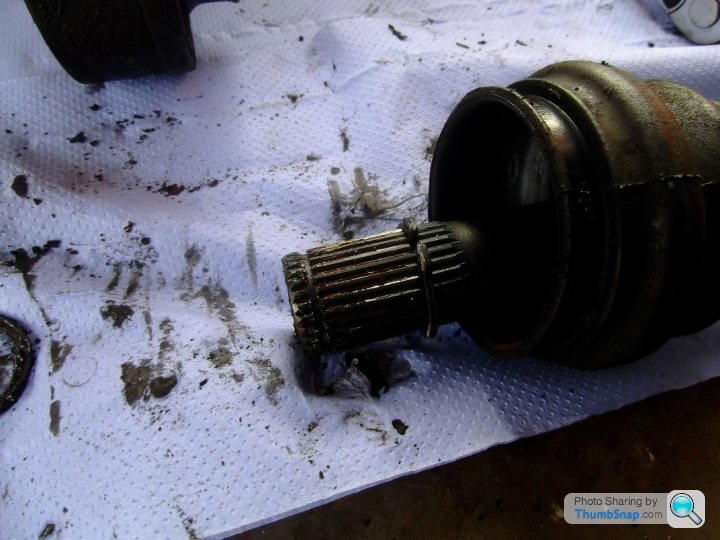
Following in on from Friday, I've now stripped inspected and re-packed the driveshaft CV joints with new grease and fitted new gaiters.
Here is the process I used:
Step 1. Remove the gaiter clips.
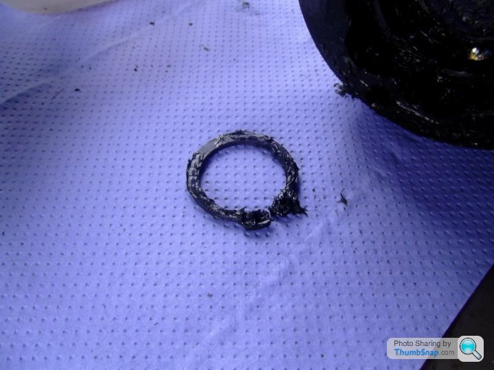
Step 2. Remove the outer circlip.

It's in there somewhere.
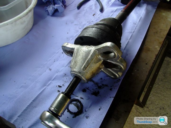
Step 3. Remove the cv joint from the driveshaft. As you can see, I used a hub puller.
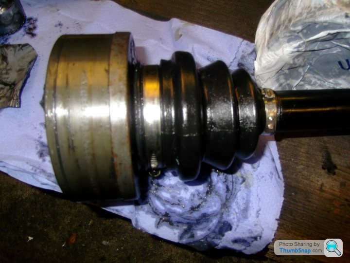
Step 4. Remove inner circlip, inspect and clean the shaft splines then fit new gaiter and refit the circlip.
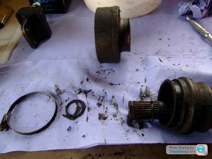
Step 5. Note the orientation of the inner race. Mine have a groove on the rear face (inboard to the driveshaft) and the thin point on the inner race points towards the wide portion of the outer race.
See pics.
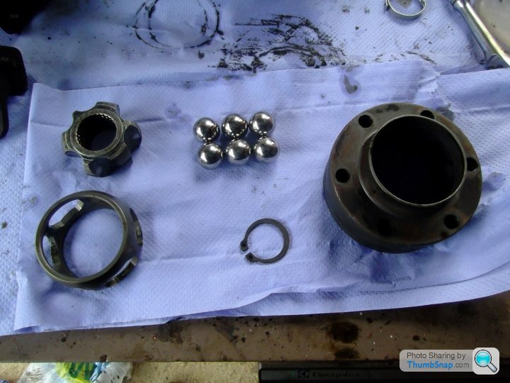
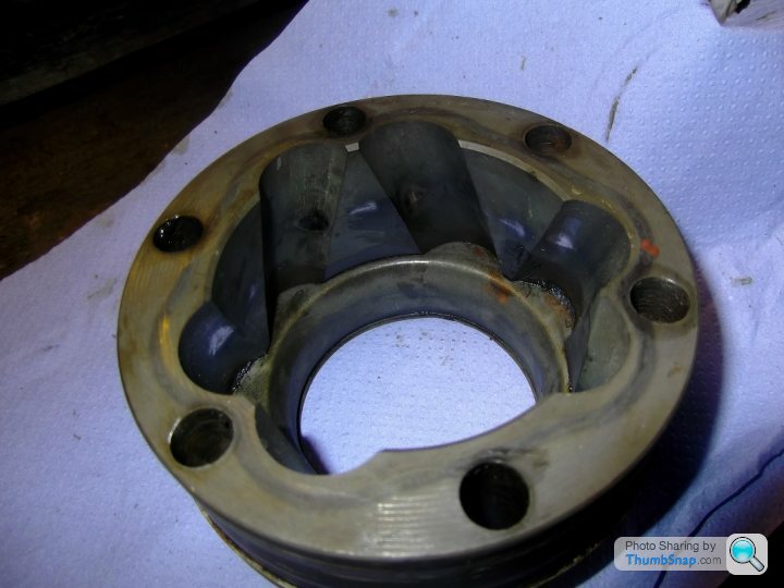
I also noted the orientation of the cage relative to the inner race.
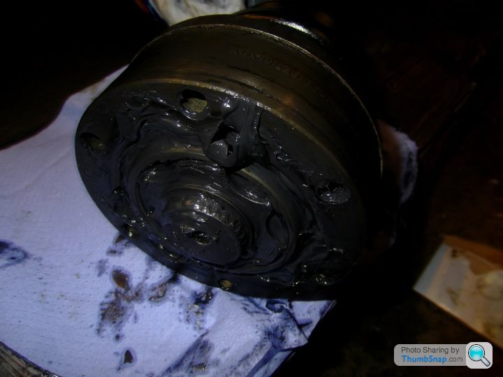
Step 6. Dismantle the race, cage and bearings. You have to rotate the cage until a bearing can be popped out.
Step 7. Clean all components. I used white spirit and a brush.
Step 8. Inspect all parts. I found witness marks (shiny bits in above pic) but no chunks missing or scores or pitting. Note: the flash on the camera has accentuated the shiny bits above.
Step 9. Apply new grease and rebuild the cage and races, working the grease in as best you can.
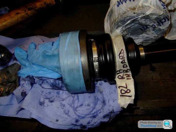
Step 10. Refit CV to Drive shaft. I used a suitable socket and hammer to drift it on, standing the driveshaft upright but standing on cardboard.
Step 11. Refit outer circlip.
Step 12. Push gaiter over CV joint collar and refit/replace gaiter clips.
Step 13. Add some rubber protection.
Step 14. Do the other three.
Here is the process I used:
Step 1. Remove the gaiter clips.
Step 2. Remove the outer circlip.
It's in there somewhere.
Step 3. Remove the cv joint from the driveshaft. As you can see, I used a hub puller.
Step 4. Remove inner circlip, inspect and clean the shaft splines then fit new gaiter and refit the circlip.
Step 5. Note the orientation of the inner race. Mine have a groove on the rear face (inboard to the driveshaft) and the thin point on the inner race points towards the wide portion of the outer race.
See pics.
I also noted the orientation of the cage relative to the inner race.
Step 6. Dismantle the race, cage and bearings. You have to rotate the cage until a bearing can be popped out.
Step 7. Clean all components. I used white spirit and a brush.
Step 8. Inspect all parts. I found witness marks (shiny bits in above pic) but no chunks missing or scores or pitting. Note: the flash on the camera has accentuated the shiny bits above.
Step 9. Apply new grease and rebuild the cage and races, working the grease in as best you can.
Step 10. Refit CV to Drive shaft. I used a suitable socket and hammer to drift it on, standing the driveshaft upright but standing on cardboard.
Step 11. Refit outer circlip.
Step 12. Push gaiter over CV joint collar and refit/replace gaiter clips.
Step 13. Add some rubber protection.
Step 14. Do the other three.


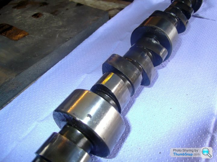
I've just had a chat with V8 Developments and the 11.5mm is valve lift not cam lift. Apologies to all for my error previously.
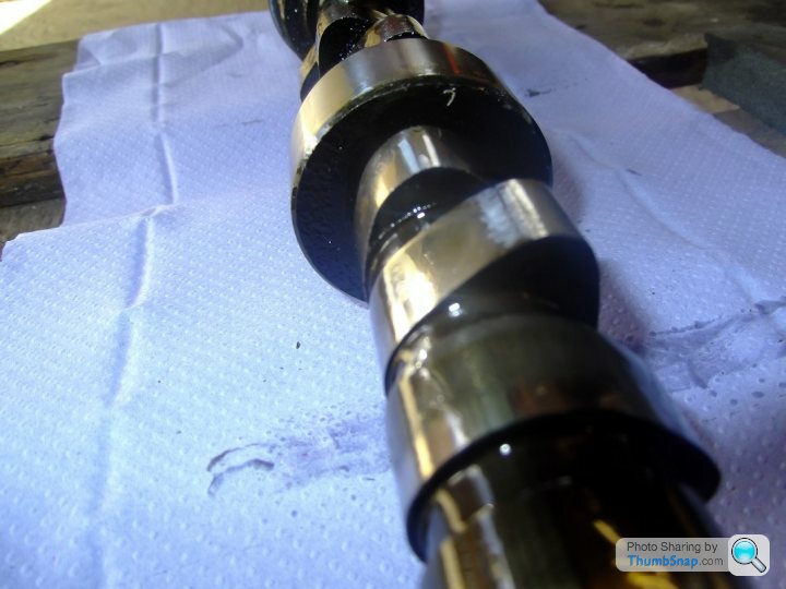
Having said that, with a ratio of 1.6 valve to cam, 11.5mm valve lift equates to 7.2mm at the lobe. So, on the one hand the cam isn't as worn across the lot as I first thought, but it is still worn by approximately 2.5mm on several of the lobes and therefore requires replacement.
Having spoken to V8 Developments, I will be going for a V8 Developments Stealth Cam as the replacement.
This weekend's update:
On Friday I had a look over the chassis now that it's back from blasting. It's not as bad as I had first thought. There was one bodged repair to the LH front outrigger diagonal, where it had obviously been repaired with the body still on.
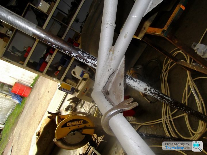
Then there were the inners of the front corners of the outriggers and the rear portions of the outriggers, as well as a section of the RH upper tube under the manifold.
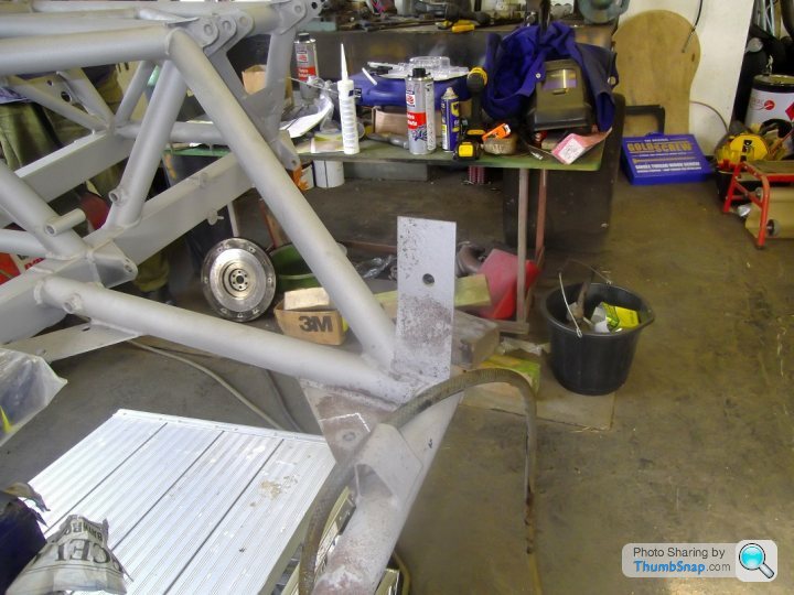
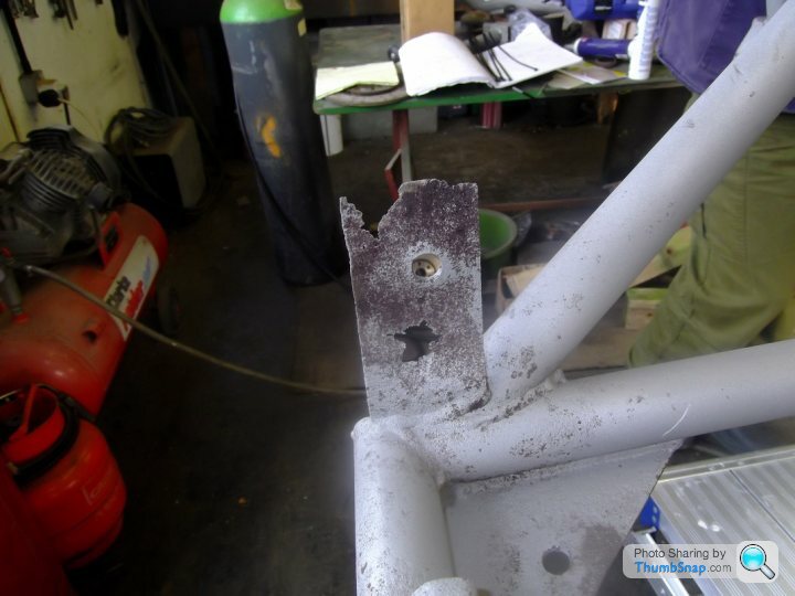
Finally, the lower left rear bolt had sheared and I broke an easy-out whilst trying to remove it, so that rear plate will be replaced.
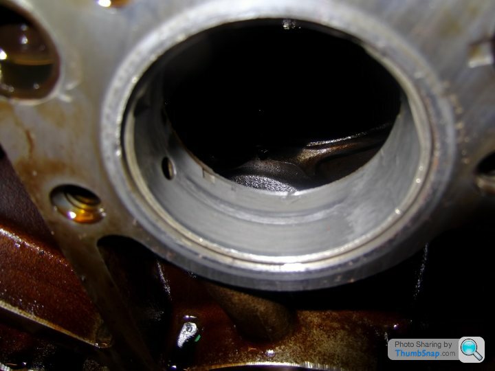
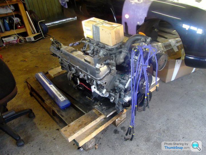
After that I started to strip the engine down ready for the replacement camshaft, only to be thwarted by the two pick up bolts that fix into the timing cover. This means the sump has to come off to access said bolts, so I need an engine stand and I will be borrowing that next weekend.
I have been pleasantly surprised by the cleanliness of the internals of the engine.
And all I did today was clean the engine block and the gearbox and replace the tail seal and the clutch release bearing.

On Friday I had a look over the chassis now that it's back from blasting. It's not as bad as I had first thought. There was one bodged repair to the LH front outrigger diagonal, where it had obviously been repaired with the body still on.
Then there were the inners of the front corners of the outriggers and the rear portions of the outriggers, as well as a section of the RH upper tube under the manifold.
Finally, the lower left rear bolt had sheared and I broke an easy-out whilst trying to remove it, so that rear plate will be replaced.
After that I started to strip the engine down ready for the replacement camshaft, only to be thwarted by the two pick up bolts that fix into the timing cover. This means the sump has to come off to access said bolts, so I need an engine stand and I will be borrowing that next weekend.
I have been pleasantly surprised by the cleanliness of the internals of the engine.
And all I did today was clean the engine block and the gearbox and replace the tail seal and the clutch release bearing.
Update from last weekend - 17-18 April:
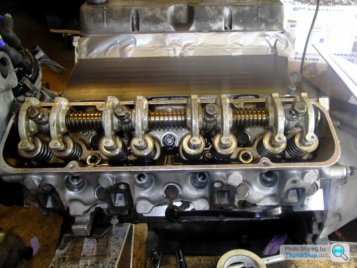
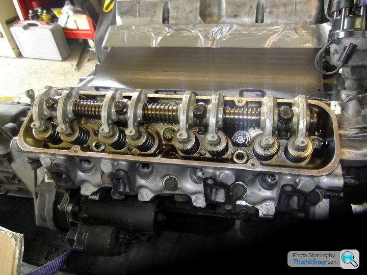
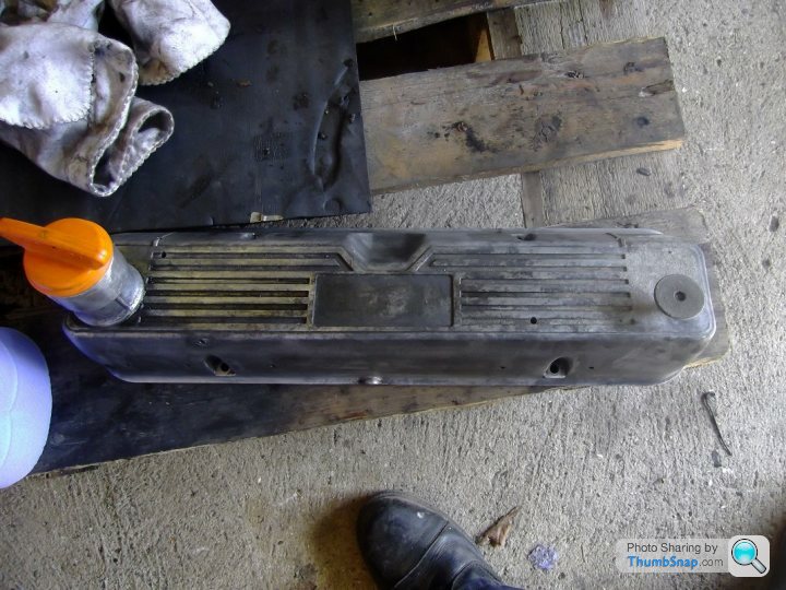
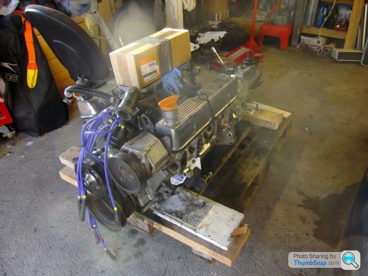
Activities last weekend consisted of cleaning down the engine - especially the rocker covers


and then replacing the camshaft and timing it up:
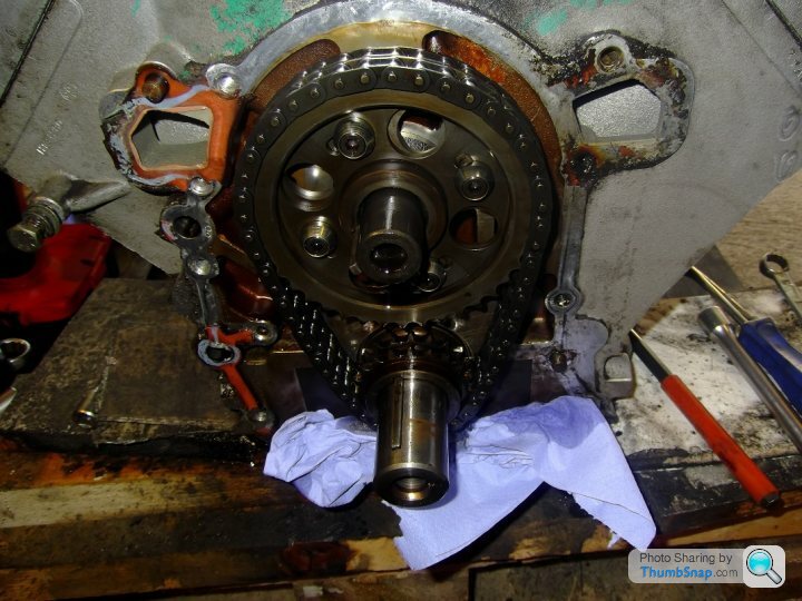
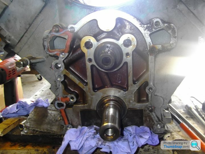
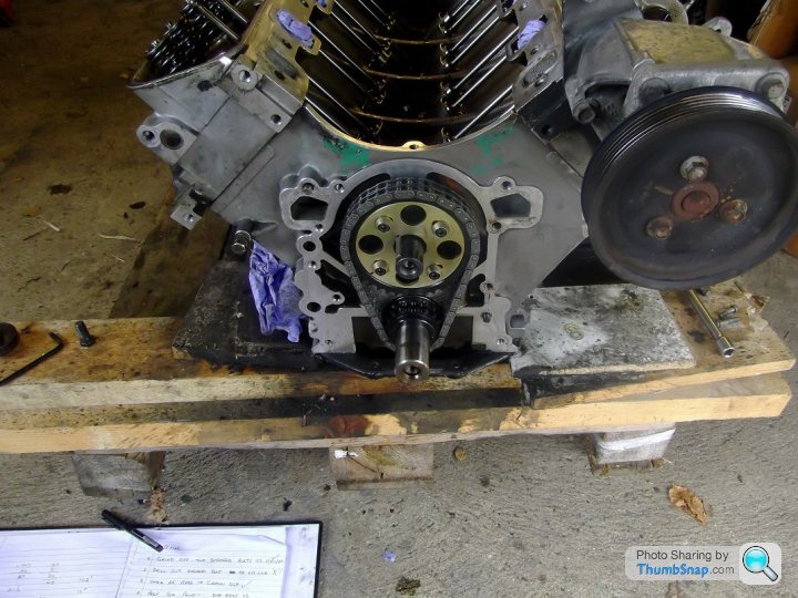
I also replaced the front cam bearing and the timing gear.
The old cam was an original TVR cam and the replacement cam is a Piper V8BP270.
The chassis repairs have been completed and tomorrow I am going to view the chassis prior to it going for paint.
Activities last weekend consisted of cleaning down the engine - especially the rocker covers
and then replacing the camshaft and timing it up:
I also replaced the front cam bearing and the timing gear.
The old cam was an original TVR cam and the replacement cam is a Piper V8BP270.
The chassis repairs have been completed and tomorrow I am going to view the chassis prior to it going for paint.
Chuffmeister said:
Great work! Can you do a complete guide for refitting and timing the cam?
Chuffy, stripping out the cam and installing the new one is a simple process: remove the intake manifold and gasket, rocker assemblies - if you are re-using pushrods, note their position and orientation when you remove them - and timing cover and then remove the timing gear, cam and followers - always fit new followers with a new cam. As for timing the cam, there are many websites that will give you a far better write up than I could. Top tip for timing the cam is: if you have the gearbox removed, remove the clutch as well and turn over the engine via the flywheel - that way you don't disturb any timing disc and the likes that you may have on the front of the crank. Because of the procedure for timing the cam, you only need to look at the timing disc once you have determined your reference points on the cam lift - I am deliberately not giving specific timing advice here as it may be mis-interpreted.
You could always try this link: http://www.v8developments.co.uk/technical/camshaft...
Chuffmeister said:
Cheers Ged. It is just the timing I don't get. I've watched a few vids on YouTube, but it isn't what they're doing, it is why they are doing it in that particular way. I guess it is one of those things, that once you've seen done in the flesh and asked a couple of questions all will become clear.
Basically, you want to find out where the Maximum Open Position (MOP) of No1 Cylinder inlet valve occurs in relation to Top Dead Centre (TDC) of the stroke for No.1 cylinder, it is relative to this reference point (TDC No.1 cylinder) where the ignition is also timed. To do that accurately for the cam timing you need to measure a given amount of reduction of valve lift either side of MOP and split the difference to pinpoint it.
The confusion that most people have is the fact that the cam rotates at half crank speed and get mixed up because the angle change on the crank is twice that on the cam, that's all.
HTH
Ged
Edited by J400GED on Friday 24th April 11:10
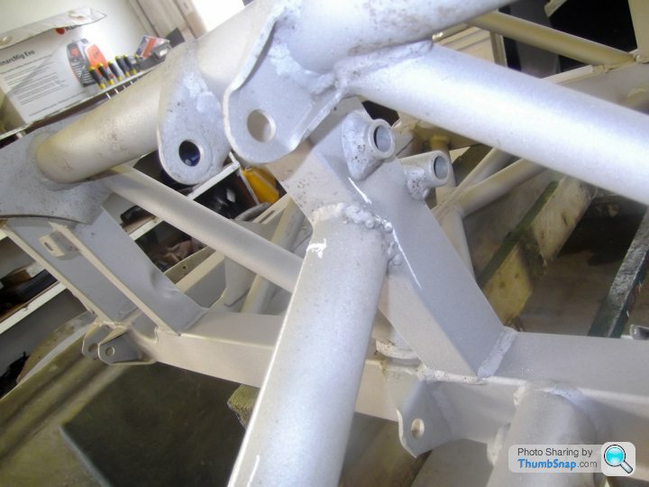
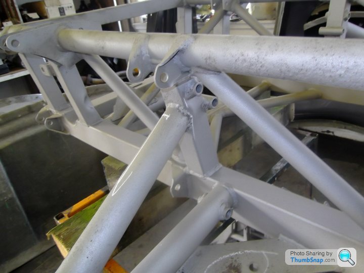
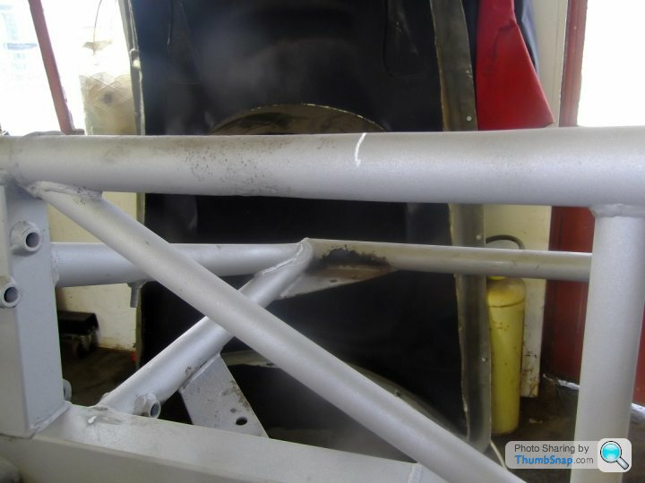
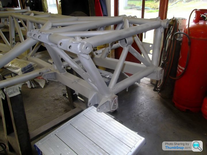
Pics of the naked repaired chassis below:
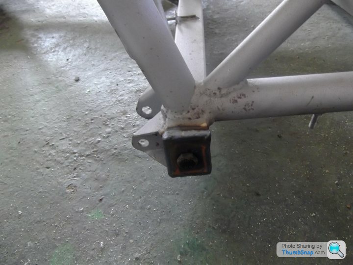
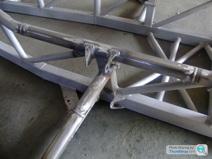
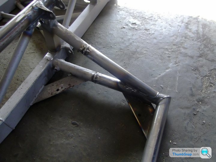
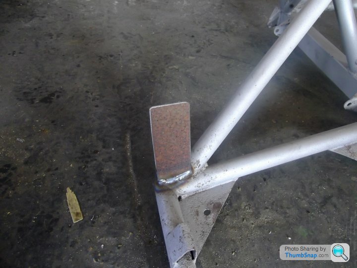
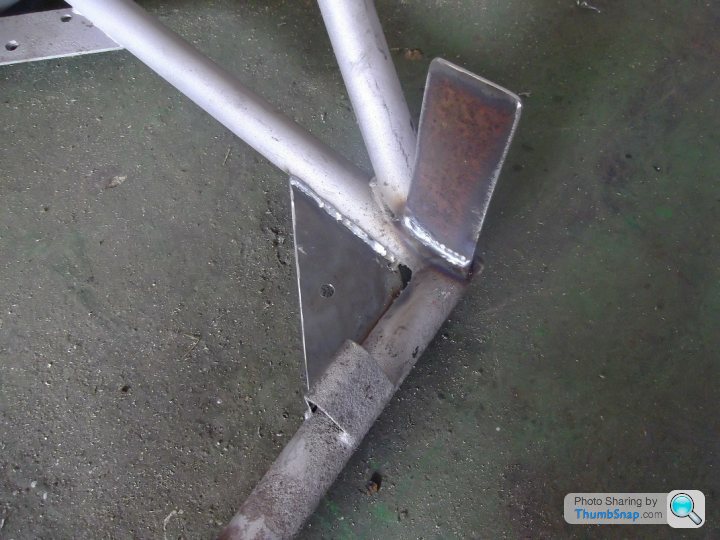
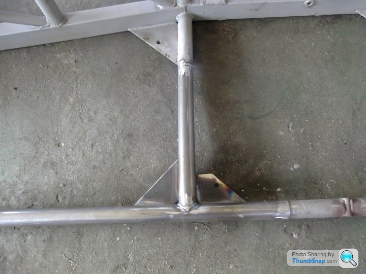
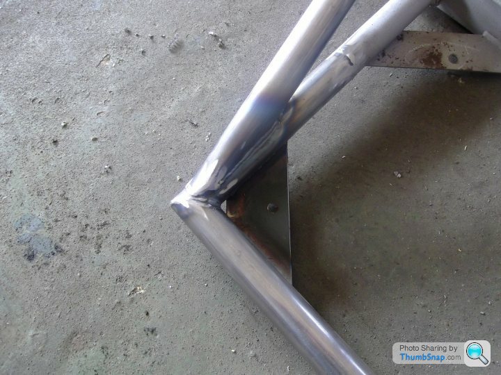
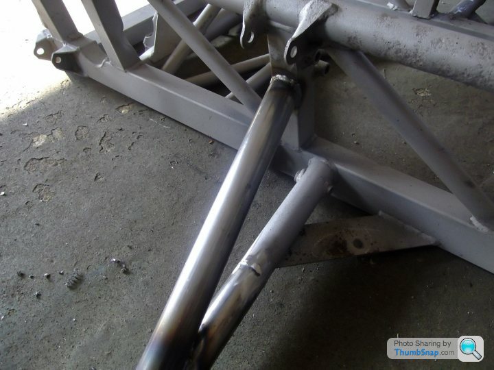
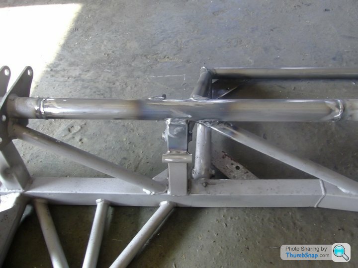
All the joints on the tubes are sleeved joints by the way.
So, next step is to be hot zinc sprayed and then 2 part painted - in white - ready for the rebuild (the chassis that is, not me!! ).
).
The chassis should be back with me in a fortnight.
That gives me 2 weeks to re-assemble the engine and gearbox ready for the chassis' return.
All the joints on the tubes are sleeved joints by the way.
So, next step is to be hot zinc sprayed and then 2 part painted - in white - ready for the rebuild (the chassis that is, not me!!
).The chassis should be back with me in a fortnight.
That gives me 2 weeks to re-assemble the engine and gearbox ready for the chassis' return.
Edited by J400GED on Friday 24th April 11:21

phazed said:
I'm thinking that the plenum might not be airtight?
The design needs a little "finessing" I must admit, but I think it could well catch on. The customizing opportunities are virtually infinite. Just working on the copyright now.Should be relatively cheap to manufacture so therefore an extremely high profit margin.

Gassing Station | Chimaera | Top of Page | What's New | My Stuff