Concentric Clutch Slave
Discussion


No, it's not a hydraulic seal; more an oil seal - suspect from the seal and machining on the reverse that on the Mondeo or whatever the body casting doubles as the input shaft seal on the gearbox nose. No harm in keeping it on ours as a barrier against dirt ingress etc (may give the primary retainer seal an easier life) but it's not going to do that much, just run against the shaft inboard of the splines.
As far as I can tell and allowing about 3mm for clutch wear, the slave and radius adaptor will need spacing 11mm off the retainer. That's a tad more than I was expecting and unfortunately means a stepped spacer will need to be turned up as it takes the slave outside the range of its locating spigot with the retainer face. The alternative is to remake the radius adaptor with an 11mm 'higher' form but I don't really want to add that much mass to the business end of the bearing. I have discounted flat spacing the thing that far too (ie without the spigot arrangement), as alignment is obviously important to be assured and maintained.
Anyone got a lathe able to handle a work piece about 110 in dia with a 30mm bore, and about 30mm high?
What about 3 of these if you're not already using some? 9mm will just mean the piston is 2mm further out and allow a bit more for a worn clutch. Just to be sure you could get a short ali tube to locate into the adapter and help allign the spacers.
http://www.retro-ford.co.uk/shop/content/clutch-re...
http://www.retro-ford.co.uk/shop/content/clutch-re...
I think it needs more positive location than that would result in; there's too high a risk of the thing going off-concentric if the clamping eases due to temperature cycles etc. The stepped spacer idea is simple and robust; RF have put me onto a local machinist who can hopefully spin it up easily when I get a drawing over to him (I so need a lathe). Also, I'm a bit wary of eating too far into the available capacity of the slave to avoid it or the clutch cover being over-stroked (3mm slack seems to be the recommendation).
Spent a happy hour under the car last night reaming the newly installed spigot bush back to 15mm (it had closed up considerably after being installed), and now have the fittings to make up a remote bleed (again thanks to Retro Ford who have a bespoke 8mm x 1.25 hose termination for the job).
Tantalisingly close to being back in business subject to getting some spanner time!
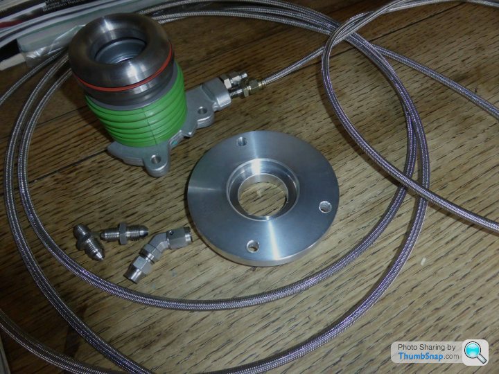
Whilst awaiting the spacer, which has been drawn and commissioned, have pulled the master cylinder and hard lines ready to replace with a new remote reservoir 0.500 bore unit (hoping this will be a more or less straight swap in the void but we shall see), and flexible lines. The bulkhead connector block took a bit of sussing and I have seen it suggested that others have had metric threads (M10x1) but mine is definitely 7/16 UNF 20 (or -4 SAE in modern money) - going to run the soft lines in -3 stainless braided Teflon - fingers crossed this will give enough extension on the slave to properly release the clutch.
The feed line into the Ford slave is M10x1; the bleed is M8 (banjo fitting would be possible with some flatting of the casting but I have a straight fitting and both lines will exit the top of the bellhousing right near the boss for the spherical bearing that locates the gearshift linkage (bleed port can then be in the engine bay near the reservoir, which I hope to have accessible rather than concealed.
This is all taking far more time than intended!
I would be nervous of these. At the moment if I am somewhere in deepest Europe and the slave cylinder fails, I can jack up the car and after removing two bolts and a banjo connection, would be able to replace the slave with the cheap one I carry in the boot (or visit the nearest LR garage); not something that can be done easily with one of these when the seals start leaking. Looks like a solution to a problem that doesn't exist.
Oldred_V8S said:
I would be nervous of these. At the moment if I am somewhere in deepest Europe and the slave cylinder fails, I can jack up the car and after removing two bolts and a banjo connection, would be able to replace the slave with the cheap one I carry in the boot (or visit the nearest LR garage); not something that can be done easily with one of these when the seals start leaking. Looks like a solution to a problem that doesn't exist.
And I'd prefer not to weigh the car down with literally kilos of unnecessary pig iron in the form of the gearbox retainer, bearing carrier, fork, pivot and slave cylinder (and spares) for the sake of trusting something a tad more elegant that functions pretty satisfactorily in squillions of vehicles all over the globe (including deepest Europe). But thanks for the encouragement Picked up the stepped spacer today and the postie delivered some hose ends etc to make up the feed lines; hopefully receive the master cylinder tomorrow.
Sorted a slight gotcha with the spacer in that the locating spigot on the rear of the slave unit has a radiused transition from the mounting face to the secondary seal carrier despite the face being machined. I hadn't initially spotted that the RF retainer has a chamfer on it to accept this. After 20 mins with a riffler file, so does the spacer - glad I clocked it as it could have resulted in the slave not sitting properly located and concentric when bolted up (or could have resulted in the body casting cracking on being tightened) - it is not at all obvious but does result in the faces not quite coming together as they should.
So, master cylinder now to hand and in - is indeed the familiar mounting hole pattern and the overall length is within a couple of mm (longer). Although the rod is much the same length, the clevis thread is imperial on the new one rather than 8mm on the TVR oem unit. Have accordingly swapped the rod after turning down the little retaining mushroom on the end to match the slightly smaller form of the one being replaced (needs to be smaller dia due to the reduced bore size).
The removable and remotely mountable fluid pot is taller and fatter than the integral unit on the TVR fitted unit so will not be able to be concealed under the standard cover if fitted directly to the master cyl. Installed like that, will protrude above cover level (would need a bespoke cover making to fit around it - my preference), but will be below bonnet height. Alternatively, could be mounted remotely (perhaps aside the plenum) with a piped run into the master cylinder (this would be dead easy with the standard cover just needing a small hole for the feed tube but otherwise being usable as is). To my eye, the former would be better but may do the latter for an easier life. Either way, fluid checking and changing will not involve removing and resealing the inspection cover, which has always been a bugbear.
Stainless line made up and installed for cylinder to bulkhead run (just fiddly head in footwell fun).
Looking good, the radius nose is taller than I thought it would be but I guess that helps reduce the height of the spacer and makes it easier to hold whilst in the lathe. I really like the spacer that looks perfect for the job, far better than stacked up spacers. Could you post a link to your master cylinder please. I couldn't find a 0.5 on Merlins site. I think I'd be tempted to make or modify my existing fibreglass cover too and keep the reservoir in the footwell, I just like a tidy engine bay.
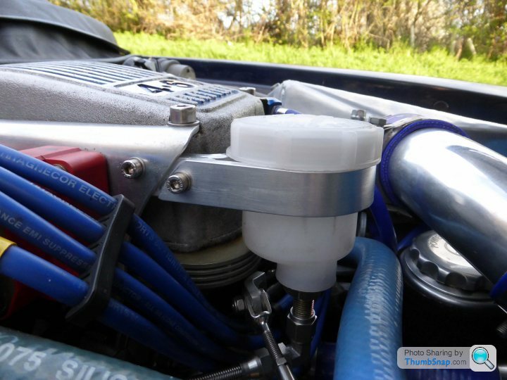
Thanks - just couldn't be arsed to mess around making a new cover so have gone for mounted on the plenum (pretty much the only spare space I had). Was quite pleased with the bracket after a bit of head-scratching (the bar behind the coil bracket picks up a couple of fasteners so is plenty stiff) - the braided feed pipe goes through the side of the oem cover and is neat enough given the rest of the chaos in the bay.
Hopefully get the box back in over the next day or two
The 0.500 master cylinder came from Rally Design - it's a copy of the familiar Girling fare but quality seems absolutely fine - just hope it pushes the slave far enough to release cleanly
Edited by Pupp on Sunday 17th April 20:52


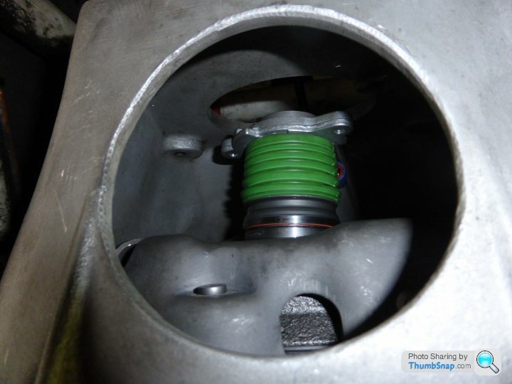
So, got the clutch installed on the flywheel and the bell-housing in this afternoon - good news is it does look quite do-able to clamp in the release bearing through the access hole. Probably not with the gearbox fully home but should be possible with the box on a trolley jack as it is being inserted. The slave is simply hanging uncompressed in the images on its lines that enter through a small hole above just to one side of the linkage eye. It is rather tighter than the perspective of the camera suggests and the top fastener will need some dexterity, but by no means out of reach. Result
 great result Gary
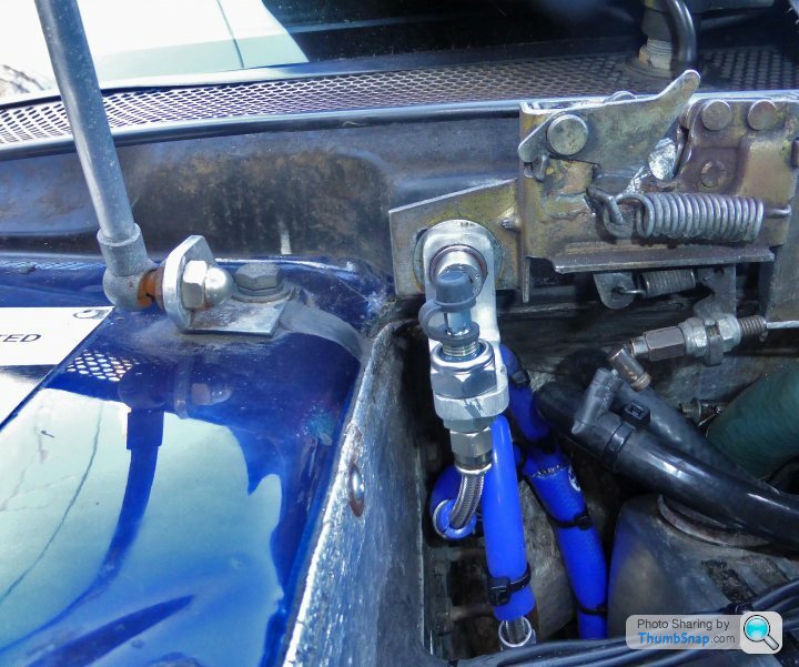
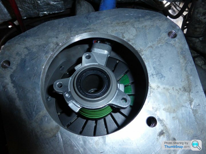
Milestone reached today in that the gearbox is back in; usual fight to get the input shaft home through the friction plate hub but good news is there was enough room to snick up the release slave onto the retainer face 
Bit fiddly tightening the three fasteners a few degrees at a time with a small hex key through the access hole but quite achievable with the box partially home (ie retainer just engaged in the bell housing). With it all home and tight, there's about 3mm headroom for wear on the compressed bearing assembly, which is pretty much exactly what was being aimed at so well happy. Next test is whether, after filling and bleeding, the small master cylinder drives the slave sufficiently to release (needs about 9mm, ie half its full range). Fingers crossed as I really am not sure and could think of no way of assessing without assembling).
Bit fiddly tightening the three fasteners a few degrees at a time with a small hex key through the access hole but quite achievable with the box partially home (ie retainer just engaged in the bell housing). With it all home and tight, there's about 3mm headroom for wear on the compressed bearing assembly, which is pretty much exactly what was being aimed at so well happy. Next test is whether, after filling and bleeding, the small master cylinder drives the slave sufficiently to release (needs about 9mm, ie half its full range). Fingers crossed as I really am not sure and could think of no way of assessing without assembling).
And now for the bad news - nope, not that the master doesn't drive the slave to sufficient extension; didn't get that far. On filling, had the dreaded trickle of fluid under the car and seems the bleed fitting has got broken when putting the gearbox back in (can feel it and could probably reinstall another in situ if the broken end could be extracted - unfortunately, no chance of that as loctited in). Ho-hum gearbox out again.
Bugger
Bugger
Gassing Station | Chimaera | Top of Page | What's New | My Stuff