Connector identity
Discussion


nickb134 said:
Hi Blitz Knowing your knowledge of 14CUX,does loss of the RPM signal to the ECU cause it to shut down or cut the fuel relay as suggested above? I am trying to figure out which sensor loss will cause a total cut and which will cause the ECU to go into limp mode? Mine currently cuts out at random. some times it will bump start other times I have to coast to a stop and restart using the starter. I can replicate the cut out symptom by turning off the fuel pump with ecumate. turn the pump on again and away she goes. Thanks in advance
The ECU needs the spark pulses to work out how often to fire the injectors, so the ECU will simply assume the engine is not turning if it does not see the pulse from the spark, so it will switch the fuel pump off and the injectors so no fuel goes in. If the fault is as far back as the amp loosing its signal, the tacho will drop to zero instantly even if the engine is still turning. The resistor in the loom between the coil and ECU is simply there to prevent spikes reaching the ECU electronics, but may be bound into the loom down near the coil. 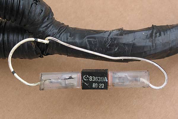
If you loose the RPM signal to the ECU due to the inline resistor itself you will also get no RPM data with RoverGauge or ECUmate, but the tacho will still work.
Paulprior said:
Hi dogbucket
Any chance of a oicture showing where you found these resistors, i found a 3.9k one near the ECU but couldnt find anything near the coil
I also tried to open up my blue connector to see whats inside, but i dont see any joint to prise open, using a meter the internals are not very uniform, some were grouped together x 4, some x5, and 1 on its own
Thanks
Paul
My loopback connector is Two gangs of 4 and two gangs of 6.Any chance of a oicture showing where you found these resistors, i found a 3.9k one near the ECU but couldnt find anything near the coil
I also tried to open up my blue connector to see whats inside, but i dont see any joint to prise open, using a meter the internals are not very uniform, some were grouped together x 4, some x5, and 1 on its own
Thanks
Paul
Gang 1 4x Brown/orange = Output from main efi r3elay
gang 2 5x Red/Black + (one position not used) = Supply out from ECU P25 which I believe is +5v for TPS, MAF, temp sensors
Gang 3 3x White/green + 1x Black = Fuse 12 connects to ECU, fuel relay P86. etc
Gang 4 3x Black/Slate + 2x Black + (one position not used) + earth at timing cover.
Hi Steve, what year is yours?, it sounds similar colours to mine, but obviously not the same😀, the ones I was most interested in was the 12v to the pump relay coil, I believe this this is the 3 x white / green group, although my fourth one was white, I get 12v on this group only after resetting the alarm and turning the ignition on, so I assume the feed is from the alarm, but it's difficult to track when you have 4 cables suddenly grouped together and all the same size and colour, I assume only one is the feed and the others supply other components.
Blitz, I was interested in your comment about the resistor and amp signals, my Rev counter still registers so I guess my amp and coil are getting the signal so I will try to find the resistor and check its connections, you mentioned that if I loose this signal the Rover Gauge Rev counter will stop, I have the RG but no experience, can I record the rpm display? Do I just press the "start log" button before I start?
Thanks
Paul

Paulprior said:
track when you have 4 cables suddenly grouped together and all the same size and colour, I assume only one is the feed and the others supply other components.
Blitz, I was interested in your comment about the resistor and amp signals, my Rev counter still registers so I guess my amp and coil are getting the signal so I will try to find the resistor and check its connections, you mentioned that if I loose this signal the Rover Gauge Rev counter will stop, I have the RG but no experience, can I record the rpm display? Do I just press the "start log" button before I start?
Thanks
Paul
Go to the options menu, and turn off all the sensors apart from RPM, so you dont get unwanted data before you turn on the logging function. It will then simply record a string of data with the RPM on it, so you can check for drop outs when you drive the car. It may take some sorting through though if the fault is not always present.Blitz, I was interested in your comment about the resistor and amp signals, my Rev counter still registers so I guess my amp and coil are getting the signal so I will try to find the resistor and check its connections, you mentioned that if I loose this signal the Rover Gauge Rev counter will stop, I have the RG but no experience, can I record the rpm display? Do I just press the "start log" button before I start?
Thanks
Paul
Hi Blitz
Thanks for confirming that loss of rpm signal will cause the engine to cut.
I am slowly building a picture of what to look at. I don't have the blue plug in my loom though.
Good pictures Dog, I know what to look for in the way of resistors now. I suspect the "lump" of insulating tape in the loom by the coil contains said resistor(s) Taking a day off tomo so I can really get into it and hopefully sort it out.
Paulprior said:
Hi Steve, what year is yours?, it sounds similar colours to mine, but obviously not the same??, the ones I was most interested in was the 12v to the pump relay coil, I believe this this is the 3 x white / green group, although my fourth one was white, I get 12v on this group only after resetting the alarm and turning the ignition on, so I assume the feed is from the alarm, but it's difficult to track when you have 4 cables suddenly grouped together and all the same size and colour, I assume only one is the feed and the others supply other components.
Paul
Was just about to post that the year is in the title of the diagram then realized my typo 1967. Doh...1997.Paul
On mine the the white/green loopback is fed from Fuse 12 which in turn is supplied directly from the ignition switch so not immobilised. SK2 in my diagram is a 6 way brown connector buried in the back of the dash. It and SK1 (clear 24 way) are the interface between the car loom and the engine loom.
Steve
I checked my blue connector again today, surprise surprise its different to yours, i seem to have 2 blocks of 4 x 12v and the rest appear to be earths, no 5v found anywhere.
I also managed to find the resistors, disconnecting one stops the engine, the other one stops the rev counter displaying but the engine still runs.
I haven't seen any problem with my light connected to the pump relay coil positive, so now i have moved to the negative side, so now the light should stay off unless the earth line is broken by the ECU, a light flashing on should be easier to detect anyway.
My second light is still on the coil, but that appears to be showing me very little as if the coil feeds the rev counter and i know the rev counter still works during a cutout or hiccup, any thoughts on where else to connect it while its still in the engine bay?
Paul
Steve_D said:
My loopback connector is Two gangs of 4 and two gangs of 6.
Gang 1 4x Brown/orange = Output from main efi r3elay
gang 2 5x Red/Black + (one position not used) = Supply out from ECU P25 which I believe is +5v for TPS, MAF, temp sensors
Gang 3 3x White/green + 1x Black = Fuse 12 connects to ECU, fuel relay P86. etc
Gang 4 3x Black/Slate + 2x Black + (one position not used) + earth at timing cover.
blitzracing said:
nickb134 said:
Hi Blitz Knowing your knowledge of 14CUX,does loss of the RPM signal to the ECU cause it to shut down or cut the fuel relay as suggested above? I am trying to figure out which sensor loss will cause a total cut and which will cause the ECU to go into limp mode? Mine currently cuts out at random. some times it will bump start other times I have to coast to a stop and restart using the starter. I can replicate the cut out symptom by turning off the fuel pump with ecumate. turn the pump on again and away she goes. Thanks in advance
The ECU needs the spark pulses to work out how often to fire the injectors, so the ECU will simply assume the engine is not turning if it does not see the pulse from the spark, so it will switch the fuel pump off and the injectors so no fuel goes in. If the fault is as far back as the amp loosing its signal, the tacho will drop to zero instantly even if the engine is still turning. The resistor in the loom between the coil and ECU is simply there to prevent spikes reaching the ECU electronics, but may be bound into the loom down near the coil. If you loose the RPM signal to the ECU due to the inline resistor itself you will also get no RPM data with RoverGauge or ECUmate, but the tacho will still work.
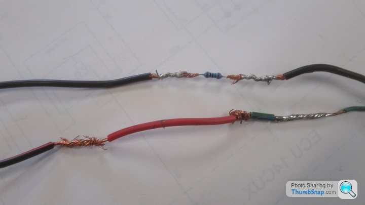
Neither of these wires have a resistor in them.
From another picture in this thread it looked like perhaps both wires should have their own resistor.
Any thoughts?
Steve
Hi Steve
I found my resistors, they looked exactly the same as the picture from Dogbucket higher up in the thread, fixed to other cables and hoses next to the alternator, from memory there are 2 sets of cables to the coil, i guess one set is the supply, but one of the other cables. white / black i think then fed straight into both resistors, around 6.4k, as mentioned above one stopped my rev counter working, the other cut the engine immediately, from info above that's probably from cutting the pump.
How did you manage to trace the cable back to pin 39?, that's where i am struggling, no drawing and too many cables the same colour
Paul
The resistors are only there to stop any spikes or nastys damaging the ECU. The lack of them could not stop it working.
So is there no provision for them at all? If the white/blue wires go direct to the coil then the original white/black wires from the coil to the spade terms for the resistors have been removed or never fitted.
So is there no provision for them at all? If the white/blue wires go direct to the coil then the original white/black wires from the coil to the spade terms for the resistors have been removed or never fitted.
dogbucket said:
The resistors are only there to stop any spikes or nastys damaging the ECU. The lack of them could not stop it working.
So is there no provision for them at all? If the white/blue wires go direct to the coil then the original white/black wires from the coil to the spade terms for the resistors have been removed or never fitted.
I'm working my way through the whole loom fixing mods and bodges along the way.So is there no provision for them at all? If the white/blue wires go direct to the coil then the original white/black wires from the coil to the spade terms for the resistors have been removed or never fitted.
The 2 wires join together a couple of inches from the coil and no evidence of resistors.
The coolant sensor does have a resistor...see if you can spot it in this mess.
Steve
Does this help at all, i just found it on the net.
"Bottom Row" - pins 1 to 13 (they're numbered from left to right as shown in the photo)
1 Red/Green Idle bypass valve - circuit 1
2 Brown/Orange Power feed to the fuel injection main relay
3 Yellow Throttle position sensor output/reference - see also 20 and 25
4 Black Oxygen sensors (ground) and to the relay that powers their heater coils
5 Grey/Black Tune resistor (through VIN LA451517 only)
6 Yellow Road speed input
7 Green/Blue Coolant temperature sensor (input) - see also 25
8 Purple/Yellow Windshield defroster input, if fitted
9 White/Light Green Diagnostic connector output
10 Black/Yellow "Check Engine" lamp
11 Yellow/White Right bank of injectors - cylinders 2, 4, 6 and 8
12 Blue/Red Main relay "request"
13 Yellow/Blue Left bank of injectors - cylinders 1, 3, 5 and 7
"Middle Row" - pins 14 to 27 (they're numbered from right to left as shown in the photo)
14 Black Ground
15 Brown "Battery" supply
16 Blue/Purple Fuel pump relay "request"
17 Grey/Yellow Purge control valve output
18 White/Pink Diagnostic connector output
19 White/Grey "Ignition" supply
20 Red Throttle position sensor (input) - see also 3 and 25
21 Yellow/Black Air conditioning thermostat input, if fitted
22 Blue/Red Air flow sensor (input) - see also 25
23 Blue Signal from the LH oxygen sensor
24 Blue Signal from the RH oxygen sensor
25 Red/Black Ground side of coolant, fuel, airflow & throttle-position sensors
26 Green/White Idle bypass valve - circuit 1
27 Black/Grey Ground
"Top Row" - pins 28 to 40 (they're numbered from left to right as shown in the photo)
28 Blue/Grey Idle bypass valve - circuit 2
29 Orange Idle bypass valve - circuit 2
30 Black Fault display data
31 Black/Green Diagnostic connector "request" input
32 Grey/White Fuel temperature sensor (input) - see also 25
33 Black/Grey Air conditioning compressor clutch relay, if fitted
34 Orange/Black Transmission gear switch signal
35 Blue/Green Air flow sensor (input) - see also 25
36 Black/Green Air conditioning condenser fan output, if fitted
37 (Not Used)
38 Brown/Black Fault display data
39 White/Black Engine speed signal cable (harness includes 6.8k ohm resistor)
40 Black Ground
Note:
1. Where two colors are given, the first is the basic color and the second is a "stripe" or "tracer" color.
2. Pins 4, 23, 24, 30, and 31 were NOT USED on vehicles that weren't equipped with catalytic converters.


 That looks fun
 , i guess youre not quite ready for a test run then
Paulprior said:
Hi
I tried this morning to shake / flex the cables near the ECU while the engine was running to see if I could try and force the intermittent cutout / misfire that I get, but found nothing, took the car for a drive and after about 5 miles it started running very poorly, stopped for petrol and that was it, no restart until I left it for 30 minutes, I tried again later and it did exactly the same, so moving the cables around has had an effect even if it's negative, does anyone know how to open up the big ECU connector to check the pins?, also I see an odd looking blue connector which I don't understand, any ideas?
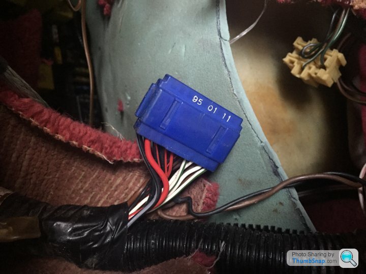
Sorry to drag this up again..however I am redoing my spagetti in the passengers footwell.The blue plug pictured, just checking it's as described..a block to terminate unused wiring.I tried this morning to shake / flex the cables near the ECU while the engine was running to see if I could try and force the intermittent cutout / misfire that I get, but found nothing, took the car for a drive and after about 5 miles it started running very poorly, stopped for petrol and that was it, no restart until I left it for 30 minutes, I tried again later and it did exactly the same, so moving the cables around has had an effect even if it's negative, does anyone know how to open up the big ECU connector to check the pins?, also I see an odd looking blue connector which I don't understand, any ideas?
Can I remove it and tiding up the wiring?
It's called a 'loop back' connector.
There are 4 groups of 'like minded' wires that join in there so it cannot just be cut out.
However, due to its location it can be subject to corrosion and can be a nightmare when trying to solve electrical issues because it is no obvious that this forms part of any circuit you are trying to trace.
There is also a Black loopback.
If corrosion is found then the safest route is to identify which wires are in which group then strip the wires and solder them.
If you need to identify the wires I can help.
Steve
Gassing Station | Chimaera | Top of Page | What's New | My Stuff