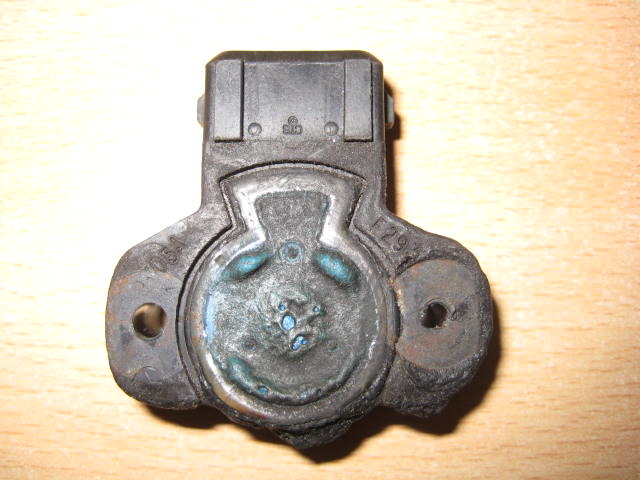
Replacement throttle pots
Discussion


Hello,
I've read a little about those and came to the opinion that they are weak by design. An hall effect tps would be far superior, but for this the output have to match.
So, do someone know what kind of signal does the Mbe ecu use? Voltage or resistance? If voltage, is it 5 or 12v?
Thanks!
Julien
I've read a little about those and came to the opinion that they are weak by design. An hall effect tps would be far superior, but for this the output have to match.
So, do someone know what kind of signal does the Mbe ecu use? Voltage or resistance? If voltage, is it 5 or 12v?
Thanks!
Julien
+
|
R
|
--> V
|
R
|
-
5v
5kohms
If memory is correct.
The voltage is digitised via an 8bit a2d converter and used by the ecu for physical butterfly position.
One vital thing that needs to be identical to the original TP is the ratio of turn vs change in resistance. This is especially true at very small butterfly openings, where the throttle position is super sensitive.
Best of luck with it!
Aide
|
R
|
--> V
|
R
|
-
5v
5kohms
If memory is correct.
The voltage is digitised via an 8bit a2d converter and used by the ecu for physical butterfly position.
One vital thing that needs to be identical to the original TP is the ratio of turn vs change in resistance. This is especially true at very small butterfly openings, where the throttle position is super sensitive.
Best of luck with it!
Aide
Edited by aide on Saturday 6th May 18:38
Strangely I was expecting you to answer 
I think those guys could help : https://acuityinstruments.com/collections/sensors-...
They do some apparently nice stuff for Hondas, should be able to do something for our beasts...
I'll get in touch with them and will let you know.
Julien
I think those guys could help : https://acuityinstruments.com/collections/sensors-...
They do some apparently nice stuff for Hondas, should be able to do something for our beasts...
I'll get in touch with them and will let you know.
Julien
They look awesome.
Being a bit OCD I noticed, when I reverse engineered the throttle position sensor codes, that they are quite sensitive to heat wrt their resistance rating.
It's one of the reasons why you need the engine hot to set the idle properly.
My romantic side attributed that quirk the AJP's personality
I'll have a look at my engine simulator and measure the resistance that corresponds to 100% open throttle. I think that's one of the more important values you need. That and the angle that it corresponds to on the original TP.
Problem is that if the ecu measures resistance, those tps will be of no use. Moreover, I've found the spec sheet and they give an output voltage of 0.5 to 4.5 V, which may be a problem. Maybe the Mbe ecu can be reprogrammed to accept those inputs?
I've written to the company, we'll see what they answer.
Julien
I've written to the company, we'll see what they answer.
Julien
All the input sensor feeds to the ecu are 12v.
i.e. Air temp, water temp, throttle position etc..
The ecu receives all transducer or resistor based input as a varying analogue voltage.
It converts this voltage to a binary number and uses the binary representation of the voltage level to decide what to do..
i.e. turn on the fans, or select the the appropriate injector duration from the fuel map based on the throttle site the TP is indicating.
It doesn't read the resistance.
Plus, the internal ecu pcb logic runs at 5v.
I think (but can't 100% remember. i.e. don't quote me!) there is a 5v O/P pin on the ecu, which could be used for the hall effect TP's.
HTH
Aide
aide said:
All the input sensor feeds to the ecu are 12v.
i.e. Air temp, water temp, throttle position etc..
The ecu receives all transducer or resistor based input as a varying analogue voltage.
It converts this voltage to a binary number and uses the binary representation of the voltage level to decide what to do..
i.e. turn on the fans, or select the the appropriate injector duration from the fuel map based on the throttle site the TP is indicating.
It doesn't read the resistance.
Plus, the internal ecu pcb logic runs at 5v.
I think (but can't 100% remember. i.e. don't quote me!) there is a 5v O/P pin on the ecu, which could be used for the hall effect TP's.
HTH
Aide
Pretty sure the TPS is 5V not 12V. I've come across very few ECU's (none)where it's not 5V.i.e. Air temp, water temp, throttle position etc..
The ecu receives all transducer or resistor based input as a varying analogue voltage.
It converts this voltage to a binary number and uses the binary representation of the voltage level to decide what to do..
i.e. turn on the fans, or select the the appropriate injector duration from the fuel map based on the throttle site the TP is indicating.
It doesn't read the resistance.
Plus, the internal ecu pcb logic runs at 5v.
I think (but can't 100% remember. i.e. don't quote me!) there is a 5v O/P pin on the ecu, which could be used for the hall effect TP's.
HTH
Aide

Have this in my toolbox in the boot for ages(years!), got it connected up and the range looks good on aides app. Just needs to run with it and some long term testing etc. A good honda friend pointed me in the right direction so I cannot take the credit. Specs are on a PDF on their website.
Hth
Craig
Hello,
this looks very good indeed! Oddly enough, it looks like it's the same as the one I've found on Borla induction website : http://www.borlainduction.com/throttle-position-se...
Their throttle potentiometer looks very similar to the one of the Cerbera. Could be a good solution? Even better as those Penny+Giles are made in UK!!! Another interesting fact is Iread that topcats use them on their race car. I would be surprised if they hadn't put some on some Cerbs if it's possible!!!!
I thinks it's really easy to test if they match with the original throttle pots :
- set your pots properly
- check that both pots give the same signal at any point of the operation range (so there are no discrepencies in the linkage function)
- change only 1 pot with the new hall effect sensor
- chack that both pot and hall effect TPS give the same value
If both still match, you're good to go! Then it's only a question of reliability.
If this does not work, I have an answer from acuity. They are ready to make some TPS for our cars, but need a group buy paid in advance to be sure to pay for the engineering costs, and say the sensors will need a machined casing because of the small amount of Cerbs / TVR on the road. They guess the price will be at leat 300USD for a set (i.e. pair). I think for now the Penny+Giles solution is more worth investigating, but acuity may be a good other solution if P+G is no good.
Julien
Jooles81 said:
I thinks it's really easy to test if they match with the original throttle pots :
- set your pots properly
- check that both pots give the same signal at any point of the operation range (so there are no discrepencies in the linkage function)
- change only 1 pot with the new hall effect sensor
- chack that both pot and hall effect TPS give the same value
If both still match, you're good to go! Then it's only a question of reliability
Julien
Hi, managed to get to step two, then I got sidetracked by life - set your pots properly
- check that both pots give the same signal at any point of the operation range (so there are no discrepencies in the linkage function)
- change only 1 pot with the new hall effect sensor
- chack that both pot and hall effect TPS give the same value
If both still match, you're good to go! Then it's only a question of reliability
Julien
Your rundown was my sentiments exactly.Now the grey matter is active i might just dive in and report back.
Thanks Craig
Hello,
So, I have an answer from acuity and penny+Giles
Acuity sound like they will give some good support to the project, though they will need some help to source an original pot and for testing.
P+G sent me directly to Jenvey, who sell a version of their sensor, saying that this may do the trick, no more. Sensor is the same as yours, Supateg, by the look of it. Still the best solution, I think, but no support to be expected, I'm afraid. I asked if th car would need a remap, but got the answer that they could not help, and there must be some forum somewhere ☺️ not very helpful.
Supateg, if you would be kind enough to test your pot? If you don't have the time, I'd be willing to buy it from you to make the test, as it looks like it's a direct fit with all the right plugs?
Julien
So I've been quietly watching this in the background, but think it's a great idea to investigate and happy to help out testing the electronics side of things
The Curtiss-Wright Contactless Throttle Position Sensor outputs (TPS280DP from it's spec sheet) at Analog (0.5 - 4.5 or 0.1 - 4.9Vdc) or PWM outputs
http://www.cw-industrialgroup.com/Products/Sensors...
Page 6 of their specification details has all the exact dimensions to measure against the original
http://www.cw-industrialgroup.com/getattachment/42...
So we should be able to take an Arduino and measure / record the ranges from 0V to +5V from both the original and the new part, and compare the ranges at say 0o, 45o, 90o 120o etc.
Or even connect a servo and turn the TPS over a controlled timeframe and record the voltages for comparison of range and spread
Anyone got a spare original throttle position sensor we can rig up and test?
Thanks Paul - looks like it might have been Nürburgring tried and tested 
So what technology do the existing OEM throttle pots use?
There's a good comparison of Magnetic Hall Effect vs. other technologies in this paper from Infineon (who make Magnetic Hall Effect Throttle Position Sensors)
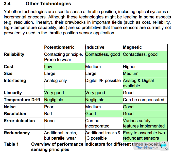
and a couple of other good papers comparing the effects of temperature and humidity on readings that I'm sure Aide will enjoy reading (contact rather than contact less, but still interesting)
Sensitivity of Contact Electronic Throttle Sensors to Control System Variation
So what technology do the existing OEM throttle pots use?
There's a good comparison of Magnetic Hall Effect vs. other technologies in this paper from Infineon (who make Magnetic Hall Effect Throttle Position Sensors)
and a couple of other good papers comparing the effects of temperature and humidity on readings that I'm sure Aide will enjoy reading (contact rather than contact less, but still interesting)
Sensitivity of Contact Electronic Throttle Sensors to Control System Variation
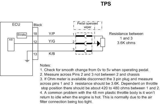
Just to hopefully answer my own question, the existing Throttle Position Sensor is apparently a variable resistor (Potentiometric) going from 0.56V at idle to 4.40V at full throttle - so that's the range we need to match
This guy in Switzerland did a graph of outputs for his Cateram running the MG throttle pot (the same as the standard Cerbera one) and you can see some pictures of it in place here (half way down)

and I'd guessing we will need to add some magnet to the end bolt of the Throttle Body nut to trigger the magentic change required for the Hall Effect sensor as per this diagram

This guy in Switzerland did a graph of outputs for his Cateram running the MG throttle pot (the same as the standard Cerbera one) and you can see some pictures of it in place here (half way down)
and I'd guessing we will need to add some magnet to the end bolt of the Throttle Body nut to trigger the magentic change required for the Hall Effect sensor as per this diagram
Gassing Station | Cerbera | Top of Page | What's New | My Stuff