Chimaera heater fan controller
Discussion


No drawing at this time but from memory last time I looked inside there was not much circuit involved. Was more for the ice warning cct than fan control.
For basic info the motor is designed and wired for three speeds which were directly wired on early cars but the later ones with the module just use the high speed wiring and control fan speed on the negative side of the motor.
Steve
For basic info the motor is designed and wired for three speeds which were directly wired on early cars but the later ones with the module just use the high speed wiring and control fan speed on the negative side of the motor.
Steve
Steve_D said:
No drawing at this time but from memory last time I looked inside there was not much circuit involved. Was more for the ice warning cct than fan control.
For basic info the motor is designed and wired for three speeds which were directly wired on early cars but the later ones with the module just use the high speed wiring and control fan speed on the negative side of the motor.
Steve
Sorry, senior moment there.For basic info the motor is designed and wired for three speeds which were directly wired on early cars but the later ones with the module just use the high speed wiring and control fan speed on the negative side of the motor.
Steve
The fan control box only does the fan. Had a quick look in mine and it is jam packed with components.
I had hoped it would be simple to 'read' the tracks and draw a circuit but that will be a tall order.
Steve
Paul Smith designed the thing for TVR, and he repairs them. You cannot get them any other way except from the breakers.
PS Electronics. Nice guy, but you will have more success if you take the box to your TVR guy and let him deal with it.
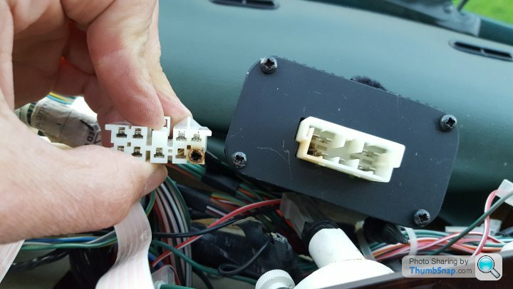
However, the most common fault is one (power?) terminal burning out on the White multiplug - you might just have a look at that first if you haven't already done so.
PS Electronics. Nice guy, but you will have more success if you take the box to your TVR guy and let him deal with it.
However, the most common fault is one (power?) terminal burning out on the White multiplug - you might just have a look at that first if you haven't already done so.
It's actually the other way round.
The supply is from fuse 14 to the fan motor then the negative from the motor is the yellow wire to the control module.
The module then earths that wire through resistances in the control module to produce the speed differences. Pins A1 & A2 are the module earths.
Steve
The supply is from fuse 14 to the fan motor then the negative from the motor is the yellow wire to the control module.
The module then earths that wire through resistances in the control module to produce the speed differences. Pins A1 & A2 are the module earths.
Steve
There are no diagrams, that are in the public domain, only the ones that have been made by others. I have made some diagrams for myself, but are the sum of a lot of hours meticulously reverse engineering the modules.
A brief for how it works,
There are no internal resistors for the fan control. It is a crude pulse width signal derived from the control potentiometer resistance divider fed into 4 Op-Amps, this output is fed through up to three transistors which will drive your fan with a somewhat simplistic square wave PWM, the lowest speed can be adjusted using the small white trim pot on the board.
In short, simply putting a switch between ground and the 12v output from the fan will make it work on or off as the fan is the LIVE component and its ground that is being switched by the module.
Edited by tofts on Tuesday 24th April 19:56
tofts said:
........There are no internal resistors for the fan control. It is a crude pulse width signal derived from the control potentiometer resistance divider fed into 4 Op-Amps, this output is fed through up to three transistors which will drive your fan with a somewhat simplistic square wave PWM, the lowest speed can be adjusted using the small white trim pot on the board.........
Thank. Good to learn new things.Steve

Thanks all, just to be clear then... The failure is caused be the spade for the negative on the module not being man enough for the job, or a bad connection causing higher than normal resistance. = Heat burning. It's my intention to 'hardwire' the negative to the board, but I wondered if adding a 15A fuse adjacent to the module may prevent future 🔥 disappointment ?
TVR450s said:
Thanks, if there's an issue with the fan the fuse would protect against increased current thus prevents o/ heating. I think. 
No it won't, motor circuits have a start up current draw higher than when up to speed hence they are fused taking this into accountYour cars blower circuit will have a blower fuse. How can adding a second fuse make all the difference?
As Steve_ D mentions above, it's all about things getting stiff

blitzracing said:
That's a good find and it can be operated from the original knob as long as its not stiffGassing Station | Chimaera | Top of Page | What's New | My Stuff