Instructions to change fuel maps on 14CUX Griffith, Chimaera
Discussion


Next step is to try and monitor a Tornado / TVR chip with the fake signal and see how close to lambda one it is without correction to see how good the set up is on my engine. This should give a good idea of what it takes to get the mapping spot on, but Im reaching the limit of what I can do with narrow band probes if the mixture is far off lambda 1. Probably a good time to dig into the pocket and fit a full wide band display.
Interesting stuff, Mark. And I think the low frequency makes sense. The Lambda sampling rate is half the spark rate per bank. By my calculations, that puts the range at about 12 Hz to 113 Hz (where it goes open loop). If the injected frequency was in that range, there would be some point where the two frequencies would align and cause aliasing. Keeping the injected frequency an order of magnitude below the minimum prevents that problem.
eliot said:
Are you able to determine how that works in the code? Is it a straight comparison to a static figure which then tells it go open. And therefore could that comparison be modified to force permanent o/l?
I've been looking into this lately. It seems that doing it this way may require one or more changes to the code section. If we can prevent closed loop by changing something in the data section instead, that would be preferable.I'm looking at the 3rd last byte in the fuel map data structure. This is a coolant temperature threshold of some sort (copied to RAM location 0x200F) and it seems to be used in the area where the open/closed decision is made. It would be very nice if we could just raise the temp threshold beyond the range the engine normally sees.
There is also a data byte outside of the fuel maps (at 0xC099) that seems to be specifically designed to control the code path in this area. Lucas may have needed a convenient way to turn Lambda control on and off during map development. So this is another possibility.
Hopefully, I'll know more soon.
danbourassa said:
I'm looking at the 3rd last byte in the fuel map data structure. This is a coolant temperature threshold of some sort (copied to RAM location 0x200F) and it seems to be used in the area where the open/closed decision is made. It would be very nice if we could just raise the temp threshold beyond the range the engine normally sees.
I thought that mark had ruled out coolant temperature for closed/open loop? Faking that signal would be easy at the hardware level.This graph shows the short term trim for a 93 NAS RRC. The sample points are 1 second apart. Coolant temp started at 68 deg F. The trim zero point is 0x8000 (32768 decimal). Upper graph is left bank, lower is right bank. Trim did not go active for more than 3 minutes.
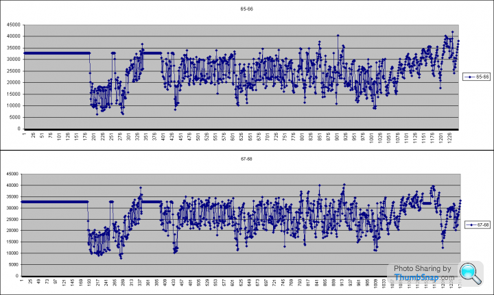
What does this mean? I don't know yet. It's complicated, but I'm pretty sure coolant temp is involved.
Notice that only the right bank went open for a short time late in the drive. I didn't know this was even possible.
The good news is that there is a magic value to force open loop!
What does this mean? I don't know yet. It's complicated, but I'm pretty sure coolant temp is involved.
Notice that only the right bank went open for a short time late in the drive. I didn't know this was even possible.
The good news is that there is a magic value to force open loop!
Edited by danbourassa on Tuesday 1st October 15:39
This is weird, heres the equivalent with the probe voltage, you can see it starts to spike at 16 seconds, but its likely you need to add 10 seconds onto this as I started the car before pressing go on the logger. I did notice a car not cycling the other day from cold with RG, but it burst into life with a quick rev, so I thought no more about it. My AF ratio gauge is wired directly to the standard probes, and you can quite clearly see the mixture cycle as the probe heats up in about 25-30 seconds. The three minute time you see would be typical for cold lambda probes without the internal heaters working (?). Ill rerun the data logger alongside RG and see how the two tally.

robertf03 said:
This evening I worked on a custom ADX to allow data tracing within tunerpro. I'll edit with the link once I zip it all up.
edit: link is http://www.flemcodesign.com/files/14CUX_CHECKSUM2....
the floating oval shows the current cell that is use per Collin and Dan's documentation.
Mark @ Tunerpro sounds pretty enthusiastic about the project and has agreed to host the files. You can now find the definition files on his site. I'm going to play with the cell tracing some this weekend before sending him the updated files and adx file.
Robertedit: link is http://www.flemcodesign.com/files/14CUX_CHECKSUM2....
the floating oval shows the current cell that is use per Collin and Dan's documentation.
Mark @ Tunerpro sounds pretty enthusiastic about the project and has agreed to host the files. You can now find the definition files on his site. I'm going to play with the cell tracing some this weekend before sending him the updated files and adx file.
I’ve finally had a chance to test data tracing on a running engine and you’ll be pleased to hear it worked. I had to create the following so would you like me to add them to the XDF file or would you mind adding them. There is no rush as I’m happy using my version for now.
TRACING MAP 2 FUEL TABLE (new)$4379
TABLE 2 SCALAR (new)$43F9
MAP 2 RPM SAFELY LIMIT (new)$4485
I've also changed TABLE 1 SCALAR to $42E7 (I know it's a work in progress
The only issue I had was the oval highlight was not always positioned exactly over the active cell and sometimes is between cells, also the refresh rate was slow. Is their anything I can change my end.
Thank you in anticipation.
Cheers Steve
Edited by stevesprint on Friday 4th October 23:42
Robert
Thank you for your emails and pointing out TunerPro doesn’t support the exact serial speed of the 14CUX at 7812.5bps. For the benefit of everyone else the data tracing slow refresh rate is caused by errors on the 14CUX serial connection with TunerPro. The connection is error free with the ignition on but once the engine is running the errors start. I wonder if it’s anything to do with the following on Colin’s protocol page at http://alum.wpi.edu/~colinb/14cux_protocol.html , and if so how does RoverGauge overcome the issue.
Thanks again for all your help & good luck with your other project.
Steve
Thank you for your emails and pointing out TunerPro doesn’t support the exact serial speed of the 14CUX at 7812.5bps. For the benefit of everyone else the data tracing slow refresh rate is caused by errors on the 14CUX serial connection with TunerPro. The connection is error free with the ignition on but once the engine is running the errors start. I wonder if it’s anything to do with the following on Colin’s protocol page at http://alum.wpi.edu/~colinb/14cux_protocol.html , and if so how does RoverGauge overcome the issue.
cmb said:
The amount of time required for the 14CUX to send a character over the serial port may change depending on its current state; for example, read requests may be serviced slightly faster before the engine has been started due to the reduced load on the processor.
Robert, I’ve tried 7808bps and 7816bps both with and without your 5ms pause and I’m happy to keep trying. I’ve also noticed in Colin/Dans code dcb.Partity = 0 and dcb.StopBits = 0 does that mean no partity and 1 stopbit?Thanks again for all your help & good luck with your other project.
Steve
stevesprint said:
Robert, I’ve tried 7808bps and 7816bps both with and without your 5ms pause and I’m happy to keep trying. I’ve also noticed in Colin/Dans code dcb.Partity = 0 and dcb.StopBits = 0 does that mean no partity and 1 stopbit?
Thanks again for all your help & good luck with your other project.
Steve
That's correct. The serial data frames are 8N1 (8 data bits, no parity, 1 stop bit).Thanks again for all your help & good luck with your other project.
Steve
Regarding the errors that occur when the engine is running: there should be no problem with baud rates slightly different from 7812.5. (The asynchronous serial protocol re-synchronizes at the start of every frame, so it's tolerant of baud rates about plus-or-minus five percent.)
danbourassa said:
This graph shows the short term trim for a 93 NAS RRC. The sample points are 1 second apart. Coolant temp started at 68 deg F. The trim zero point is 0x8000 (32768 decimal). Upper graph is left bank, lower is right bank. Trim did not go active for more than 3 minutes.
What does this mean? I don't know yet. It's complicated, but I'm pretty sure coolant temp is involved.
Notice that only the right bank went open for a short time late in the drive. I didn't know this was even possible.
The good news is that there is a magic value to force open loop!
Just to make sure I was not going quietly mad, here's the results from running the data logger alongside RoverGauge. The plot on the left shows the lambda output rising as the probes heat up, and then start switching, so lambda trim must be working at this point, and RoverGauge still shows zero trim. I would think there is a timer somewhere in the software addition to the physical voltage switching. Even though the lambda output has clearly risen it took a blip of the throttle to start the switching.What does this mean? I don't know yet. It's complicated, but I'm pretty sure coolant temp is involved.
Notice that only the right bank went open for a short time late in the drive. I didn't know this was even possible.
The good news is that there is a magic value to force open loop!
Edited by danbourassa on Tuesday 1st October 15:39

How does a normally closed loop map run open loop? I'm still trying to understand this, but here I am so far. There are bytes in RAM that are used, not as numerical values but, as individual bits that are toggled according to various conditions in the code. A number of these bits are examined at a point in the spark interrupt where the closed/open loop decision is made. The relevant bits are Boolean OR'ed (meaning any one bit will force open loop). Here is a list of bits and what causes them to be set.
0x0087 Bit 0: Set when MAF > 2.0 Volts AND Coolant Temp < 50 degrees C
0x0087 Bit 1: Set when MAF fault occurs
0x0087 Bit 3: Set when throttle pot is > 91% (approx 4.6 Volts)
0x0087 Bit 4: (will force open loop but otherwise unused and should stay zero)
0x0087 Bit 5: Set when RPM > 3400 (this value stored in PROM at 0xC0A7)
0x0087 Bit 7: Set & cleared in spark interrupt (todo)
0x0085 Bit 7: Low engine RPM (less than 505 RPM, changed to 375 RPM for op-pride cold weather chip)
0x0089 Bit 7: (todo)
0x008C Bit 3: (todo, bit 008C.2 seems to correlate to the open/closed condition)
0x008A Bit 6: Set at start up, cleared at timeout from 3rd row of 3 x 12 fuel map table (1 Hz count down)
0x205B Bit 2: Set when
1) Road speed is GT 4 KPH
AND
2) Bit 0086.7 is set
AND
3) Coolant temp is cooler than 83 deg C
0x205B Bit 5: Set when
1) Bit 0086.7 is set
AND
2) Bit 008A.5 is zero (park, neutral or manual, not drive)
AND
3) Road speed < 4 KPH
AND
4) Coolant temp is cooler than 40 deg C
0xC099 This is a byte value in PROM which should normally be zero. Set to non-zero to force open loop.
danbourassa said:
0x0087 Bit 4: (will force open loop but otherwise unused and should stay zero)
Could RoverGauge read the complete bytes change Bit 4 and send the complete byte back?danbourassa said:
0x0087 Bit 5: Set when RPM > 3400 (this value stored in PROM at 0xC0A7)
I’m thinking if Bit 5 is set when the revs exceed the value stored at 0xC0A7 in the PROM would changing the value at 0xC0A7 to 500 force open loop above 500 revs. Hummm, that’s strange C0A7 in a few PROM I have is 08 9D and that’s 2205 in decimal, I must be having another blonde moment.danbourassa said:
0xC099 This is a byte value in PROM which should normally be zero. Set to non-zero to force open loop.
Would it be possible for RoverGauge to set/unset this address in memory to force open loop on and off.Just a thought
Steve
Gassing Station | Griffith | Top of Page | What's New | My Stuff