Instructions to change fuel maps on 14CUX Griffith, Chimaera
Discussion


Griffian said:
but in principle the electronics for a wave divider are quite simple for division by powers of 2 which will get it in the right ballpark for time measurements. I need to learn a bit for the electronics though.
Griffian said:
I cant lop teeth off as the signal drives the dash speedo, but I'm thinking about knocking up a box of tricks to take the T5 TVR style signal and divide it to a slower rate to suit my O2 sensor, and if I can generate something which the ECU will tolerate it would be a nice bonus.
Here's the frequency divider Colin knocked up to re-calibrate the signal for the speedo and ECU when Colin and his father Dan replaced their LT77 with a T5.cmb on page 28 said:
Just in case anyone finds it interesting or useful, here's some info about what we did to deal with the road speed signal while doing the T5 swap on Dan's Griffith:
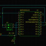
I think the LT77's output shaft sensor was producing 5 pulses per every 4 rotations, but the new tone wheel with the T5 installation would produce something like 17 pulses/rotation. I decided to build a small programmable 12V frequency divider so that the new high-frequency pulse train could be stepped down to the equivalent LT77 rate. I went with a TI MSP430 micro because that made it easy to change the software for different behavior if required.
(And buying MSP430s doesn't exactly break the bank.)
Note that this is very much a prototype. I can't guarantee that it'll work for everyone, but it's certainly a starting point for those that want to adapt the fast waveform of the multi-tooth tone wheel to the instruments in a car originally fitted with the LT77.
Here's the schematic:
and here's the MSP430 code:
http://pastebin.com/5FGMtAmB
JulianI think the LT77's output shaft sensor was producing 5 pulses per every 4 rotations, but the new tone wheel with the T5 installation would produce something like 17 pulses/rotation. I decided to build a small programmable 12V frequency divider so that the new high-frequency pulse train could be stepped down to the equivalent LT77 rate. I went with a TI MSP430 micro because that made it easy to change the software for different behavior if required.
(And buying MSP430s doesn't exactly break the bank.)
Note that this is very much a prototype. I can't guarantee that it'll work for everyone, but it's certainly a starting point for those that want to adapt the fast waveform of the multi-tooth tone wheel to the instruments in a car originally fitted with the LT77.
Here's the schematic:
and here's the MSP430 code:
http://pastebin.com/5FGMtAmB
If you manage to reduce the road speed signal enough that "the ECU will tolerate" you then could try modifying the 14CUX speedo calibration in the code, Dan's example below may give you some ideas.
Dan said:
The road speed does not, as far as I know, have an impact on fueling however the idle mode threshold is important.
It should switch at 4 MPH or about 3 KPH. You're lucky that the road speed is off by half instead of some odd amount. There are 2 ways to fix this easily:
It should switch at 4 MPH or about 3 KPH. You're lucky that the road speed is off by half instead of some odd amount. There are 2 ways to fix this easily:
1)  If you look at the bottom of roadSpeed.asm you will find this line
             inc    $2002       ; increment X2002 when road speed is not zero

You can duplicate this line so that the variable gets incremented twice.
2)  This is a more efficient way. If you look near the top of the file, you will see this line:
   .LD38D    stab    roadSpeed  ; store actual road speed (or 176 KPH limit)

You should change this to:
   .LD38D    aslb               ; double the value
             stab    roadSpeed  ; then store it
Edited by stevesprint on Friday 26th February 20:17
tahiti-range
Sorry for the delayed response and delayed welcome to this 14CUX team effort, I'm pleased you're making good 14CUX progress from all the replies.
You and your father have been very busy installing a 4.6, removing the cats and changing the tune resistor. I'm even more impressed you've successfully installed the Secu3T open source programmable ignition and got it working reliably, sounds like something I should consider.
The AFM row scalar is more related to engine displacement than the main fuel table multiplier. You can change the main scalar for small variations in cc or engine mods like cams but for big cc changes like 3.9 to 4.6 you should really change the AFM row scalar, otherwise on fuel load you'll hit the bottom row of the fuel table too easily.
1st, change the AFM row scalar so you hover between the last two rows on full load.
2nd, change the main scalar so you have hex FF in the full load cells
3rd, remap the reset of the table
Spitfire4v8 explained the main multiplier much better on Page 16
The CO Trim screw on the AFM and the lambda long trim only effect the squirt duration below 3,400rpm, its influence on fuelling gradually tails off as the rpms approach 3,400rpm and not suddenly cut.
Here's the wiring diagram for the 20AM. http://www.pistonheads.com/gassing/topic.asp?h=0&a...
TVR2967's own revision is very good and reliable but several 14CUX DIY owners run R3652 with LR's final refinements including the MIL lamp that gives a reassuring flash each time the ignition is turned on. During last Autumn I successfully ran my R3652 with the hot start fix as it allows you to turn down the lingering idle while slowing down (via the base idle screw) without causing any adverse effect, this is more of an issue with TVR's higher idle speed.
Tahiti
Finally, thanks for all your questions, they are great and made me realise I need to add all this overview explanation information to my website.
Good Luck and please don't hesitate to ask any further question.
Steve Sprint
If you run your 4.6 with the standard 3/5 AFM on a 3.9 eprom you'll use rows too far down 3.9 fuel table, therefore I suggest you try my 430 precat map
http://www.stevesprint.com/remap-14cux/bins/R3652_...
as it has the same AFM row scalar of 91 as TVR 450 and 500 eproms plus it contains a very rich (safer) non-cat map and multiplier for larger capacities.
I wouldn't recommend running Land Rover's 4.2 or TVR 450 or 500 eproms their non-cat map (2) are only for a 3.9.
Also, I don't advise changing your AFM Row scalar without an AFR gauge because changing the active row dramatically changes the fuelling because you'll start using the hex values in a different row for the same airflow.
Sorry for the delayed response and delayed welcome to this 14CUX team effort, I'm pleased you're making good 14CUX progress from all the replies.
You and your father have been very busy installing a 4.6, removing the cats and changing the tune resistor. I'm even more impressed you've successfully installed the Secu3T open source programmable ignition and got it working reliably, sounds like something I should consider.
tahiti-range said:
I have a question about the multiplier, how does it work ? I mean, it simply multiplies the fuel map by a constant value, or is it dependent on other parameters ?
Yes, the main fuel multiplier is simply multiplied by the active cell in the main fuel table and effects the "squirt duration" for every cell in the fuel table, It is not dependent on any other parameter and can be changed independently. tahiti-range said:
I did compare map from 3.9-4.2-4.3 and 4.6 engines, and this multiplier and the row scalar are the main differences between the except from slight differences in fuel map.
Is that right to say that it is related to the engine displacement ? Is it possible to adapt a 3.9 eprom to a 4.6 engine just by changing this value ?
Yes, its possible to adapt a 3.9 eprom to a 4.6 engine by changing the main multiplier and AFM row scalar followed by a full remap of every cell, that's what TVR did. Starting from a Land Rover 4.2 map would be a better option as the Land Rover 4.2 eprom contains other tuning parameter tweaks to suit the bigger cc, for example the cranking fuelling table.Is that right to say that it is related to the engine displacement ? Is it possible to adapt a 3.9 eprom to a 4.6 engine just by changing this value ?
The AFM row scalar is more related to engine displacement than the main fuel table multiplier. You can change the main scalar for small variations in cc or engine mods like cams but for big cc changes like 3.9 to 4.6 you should really change the AFM row scalar, otherwise on fuel load you'll hit the bottom row of the fuel table too easily.
1st, change the AFM row scalar so you hover between the last two rows on full load.
2nd, change the main scalar so you have hex FF in the full load cells
3rd, remap the reset of the table
Spitfire4v8 explained the main multiplier much better on Page 16
spitfire4v8 said:
The fuel map multiplier in my mind changes the time allocated to each bit
(normally termed microseconds per bit in other aftermarket ecus).
What I have been doing is to massage the fuel multiplier to get the fuelling correct at the richest point
on full throttle power runs on the dyno with FF in the load sites passed through during the run, then leaving the multiplier alone and going back and correcting all the other fuel map sites to get the mixture where I want it.
In this way you can maximise the resolution of the fuel map which becomes important when you are dealing with small numbers in the fuel map around idle and trailing throttle.
The multiplier therefore does become engine size dependant because a big engine will draw more air, will require more fuel, or in the case of the multiplier part - more microseconds of fuel squirted per bit.
tahiti-range said:
I checked the CO trim voltage of my 3AM Lucas AFM, and it gives me strange results. I have about 3.4 - 4.7V
I agree with Blitz, sounds like your CO trim screw doesn't work correctly, the ECU rounds down the CO trims voltages above 2.5v down to 2.5v. The CO trim mid point is 1.25v and has the same effect as 0% Lambda long trim, I always remember turning the CO Trim screw clockwise increases the fuel.tahiti-range said:
My car was originally a CAT car, and the CO trim is about 2.50V. I don't want to disable, I wonder if I have to modify it to 1.4V as Steve explained if I want to run NON CAT map 2, tuned by myself.
OEM fuel maps are designed to run with the CO trim and Lambda long trim set in the mid point of 1.25v or 0%, however to improve idle smoothness we tend to set the CO Trim to 1.4v which is slightly richer, this has the same effect as +12% lambda long term trim.tahiti-range said:
If I leave the CO trim to 2.50V, will the main scalar be taken into account correctly ?
Yes, but I don't recommend 2.5v due to the point above. The CO Trim does NOT change how the main scalar is applied or how far you go down the main fuel table on full load. The CO Trim screw on the AFM and the lambda long trim only effect the squirt duration below 3,400rpm, its influence on fuelling gradually tails off as the rpms approach 3,400rpm and not suddenly cut.
tahiti-range said:
I put a pot to tune the CO trim and it is now at 1.3V.
When remapping you should technically have the CO trim set to the mid point so you have maximum adjustment either way, however for convenience I suggest you stick to 1.4v so you don't have to change your CO trim each time you change eproms.Here's the wiring diagram for the 20AM. http://www.pistonheads.com/gassing/topic.asp?h=0&a...
tahiti-range said:
As I understand voltage from the 3AM and 20AM are different, so I would like to adapt the voltage map of the 14CUX to fit the 20AM.
The 3/5AM and 20AM both output the same signal voltage for their max airflow (Mark can confirm the voltage) but with a bigger AFM you'll find it harder to hit the max airflow of the AFM and therefore produces a low signal for the same airflow. This means for the same airflow your engine will not go as far down the fuel table with a 20AM so you'll have to change the AFM row scalar to push the active cell nearer the bottom row on full load.tahiti-range said:
Which map have I to adjust ?
You can adjust any eprom for the 20AM.TVR2967's own revision is very good and reliable but several 14CUX DIY owners run R3652 with LR's final refinements including the MIL lamp that gives a reassuring flash each time the ignition is turned on. During last Autumn I successfully ran my R3652 with the hot start fix as it allows you to turn down the lingering idle while slowing down (via the base idle screw) without causing any adverse effect, this is more of an issue with TVR's higher idle speed.
tahiti-range said:
The adjustment to be done is to increase by 15% the values as I understood ?
Not sure, you really need a wideband gauge to check the AFR.tahiti-range said:
Or should I just play with the Row scalar and Row offset ?
YES, you should experiment with the Row Scalar and Row offset until you hover between the last two rows on full load and idle is ideally one row down.Tahiti
Finally, thanks for all your questions, they are great and made me realise I need to add all this overview explanation information to my website.
Good Luck and please don't hesitate to ask any further question.
Steve Sprint
============ EDIT ===============
If you run your 4.6 with the standard 3/5 AFM on a 3.9 eprom you'll use rows too far down 3.9 fuel table, therefore I suggest you try my 430 precat map
http://www.stevesprint.com/remap-14cux/bins/R3652_...
as it has the same AFM row scalar of 91 as TVR 450 and 500 eproms plus it contains a very rich (safer) non-cat map and multiplier for larger capacities.
I wouldn't recommend running Land Rover's 4.2 or TVR 450 or 500 eproms their non-cat map (2) are only for a 3.9.
Also, I don't advise changing your AFM Row scalar without an AFR gauge because changing the active row dramatically changes the fuelling because you'll start using the hex values in a different row for the same airflow.
Edited by stevesprint on Saturday 27th February 19:13
stevesprint said:
Here's the frequency divider Colin knocked up to re-calibrate the signal for the speedo and ECU when Colin and his father Dan replaced their LT77 with a T5.
If you manage to reduce the road speed signal enough that "the ECU will tolerate" you then could try modifying the 14CUX speedo calibration in the code, Dan's example below may give you some ideas.
Sorry for the slow reply - I have been away quite a bit and only just caught up with PH. Thanks for that information - it looks like it should save me a lot of experimentation. BTW, I have my O2 sensor - just got to fit it now.cmb on page 28 said:
Just in case anyone finds it interesting or useful, here's some info about what we did to deal with the road speed signal while doing the T5 swap on Dan's Griffith:
JulianIf you manage to reduce the road speed signal enough that "the ECU will tolerate" you then could try modifying the 14CUX speedo calibration in the code, Dan's example below may give you some ideas.
Dan said:
The road speed does not, as far as I know, have an impact on fueling however the idle mode threshold is important.
Edited by stevesprint on Friday 26th February 20:17
As requested I’ve made my AFR logger easier to read and added the date and time to the log file name and the window title, help yourself www.stevesprint.com/remap-14cux/AFR_Logger.zip .
stevesprint said:
As requested I’ve made my AFR logger easier to read and added the date and time to the log file name and the window title, help yourself www.stevesprint.com/remap-14cux/AFR_Logger.zip .
Hi SteveSorry I didn't get back to you straight away.
This is just what I was after

It’s really going to help with my data correlation project!
I’ll be able to test it thoroughly in the next week or two
and let you know how I get on.Cheers
MPO
MPO said:
Hi Steve
Sorry I didn't get back to you straight away.
This is just what I was after
It’s really going to help with my data correlation project!
I’ll be able to test it thoroughly in the next week or two and let you know how I get on.
Cheers
MPO
GlynSorry I didn't get back to you straight away.
This is just what I was after
It’s really going to help with my data correlation project!
I’ll be able to test it thoroughly in the next week or two
and let you know how I get on.Cheers
MPO
Interesting and sounds like we are up to the same tricks.
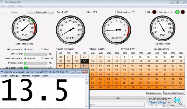
Here's a very small and simple program I wrote to merge our LC2 wideband AFR and RoverGauge logs, its not perfect but does the job. It also creates extra records above 5,200rpm with correct AFR readings when the 14CUX runs out of time for data logging.
www.stevesprint.com/remap-14cux/LogMerger&Pivo....
I then open the merged log in Excel and within a few clicks create a pivot table like the one below, I might even be able to create an Excel macro to automatically create the pivot table.

Maybe we should compare notes offline.
Cheers, Steve
Hi Steve
We certainly are barking up the same tree, I was logging data most of last year combining the data and producing many pivot tables, these then helped me produce a best fit tune for my Pre CAT. I was regularly crunching 50K+ AFR and Rover Gauge data points on short runs and could see how my physical upgrades (i.e. installing a 20am etc..) changed my AFR and I then changed my fuelling accordingly (even on the side of the road!).
Griff is back on the road from this weekend, I have so many upgrades planned and feel quite confident I can get the best out of these, working the fuelling to give me the best AFR across the board and not just at WOT.
Shunting is a thing of the past for me.
I’ll take a look at your program too and I’m sure it will be really useful and give you some feedback.
Cheers
MPO
We certainly are barking up the same tree
, I was logging data most of last year combining the data and producing many pivot tables, these then helped me produce a best fit tune for my Pre CAT. I was regularly crunching 50K+ AFR and Rover Gauge data points on short runs and could see how my physical upgrades (i.e. installing a 20am etc..) changed my AFR and I then changed my fuelling accordingly (even on the side of the road!).Griff is back on the road from this weekend, I have so many upgrades planned and feel quite confident I can get the best out of these, working the fuelling to give me the best AFR across the board and not just at WOT.
Shunting is a thing of the past for me.
I’ll take a look at your program too and I’m sure it will be really useful and give you some feedback.
Cheers
MPO
Glyn
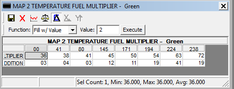
Sorry for the delayed response I’ve been busy working in the garage as we you do. Anyway, here's my quick & rough interpretation of Dan's comments in the code.
The top row (the column headings) are coolant temperature counts in hex not degrees Celsius or Fahrenheit and determines which column of data comes into play. The higher hex values on the right are lower temperatures and the lower hex value on the left are higher temperatures.
I think the third row is the multiplier and the second rows is added to the multiplier, see the code below.
A Hex temperature count can be converted to degree Celsius with the following table that Dan created. The Hex temperature count left digit is rows down and the right hex digit is columns across, therefore temp count Hex 23 means 2 down & 3 across and therefore is 87 degs C.
EXCEEDED!! therefore I think the column with the exceeded temp count comes into play, i.e. the column to the right.
The suba in the code leaves the difference of actual engine temp and column heading temp which is then multiplied by the 3rd row. The result is then mutliplied 4 times and finally the second row is added.
Glyn, sorry but you did ask.
Dan,
Please confirm the column with the higher temp count comes into play, i.e. the column to the right and I have the 2nd and 3rd rows right.
Sorry for the delayed response I’ve been busy working in the garage as we you do. Anyway, here's my quick & rough interpretation of Dan's comments in the code.
The top row (the column headings) are coolant temperature counts in hex not degrees Celsius or Fahrenheit and determines which column of data comes into play. The higher hex values on the right are lower temperatures and the lower hex value on the left are higher temperatures.
I think the third row is the multiplier and the second rows is added to the multiplier, see the code below.
A Hex temperature count can be converted to degree Celsius with the following table that Dan created. The Hex temperature count left digit is rows down and the right hex digit is columns across, therefore temp count Hex 23 means 2 down & 3 across and therefore is 87 degs C.
This table is not in the ecu and Dan created it so we can convert the temperature counts to a human friendly temperature.
; Temperature Count Conversion Table into Degrees C.
; 1st down 2nd across therefore x16 = 100 Degs C
;     0   1   2   3   4   5   6   7   8   9   A   B   C   D   E   F
; 0  130,129,127,126,124,123,121,120,118,117,115,114,112,111,109,108,  0
; 1  106,105,104,103,102,101,100, 99, 98, 97, 96, 95, 94, 93, 92, 91,  1
; 2   90, 89, 88, 87, 86, 85, 84, 83, 82, 81, 80, 79, 78, 77, 76, 75,  2
; 3   74, 73, 72, 71, 70, 70, 69, 68, 67, 66, 65, 64, 63, 63, 62, 61,  3
; 4   60, 59, 59, 58, 58, 57, 56, 56, 55, 55, 54, 54, 53, 52, 52, 51,  4
; 5   51, 50, 50, 49, 49, 48, 48, 47, 47, 46, 46, 45, 45, 44, 44, 43,  5
; 6   43, 42, 42, 41, 41, 40, 40, 39, 39, 38, 38, 37, 37, 36, 36, 35,  6
; 7   35, 35, 34, 34, 33, 33, 32, 32, 31, 31, 30, 30, 29, 29, 28, 28,  7
; 8   28, 28, 27, 27, 26, 26, 26, 25, 25, 24, 24, 23, 23, 23, 22, 22,  8
; 9   22, 21, 21, 20, 20, 19, 19, 18, 18, 17, 17, 16, 16, 15, 15, 14,  9
; A   14, 14, 13, 13, 12, 12, 11, 11, 10, 10,  9,  9,  8,  8,  7,  7,  A
; B    7,  7,  6,  6,  6,  5,  5,  5,  4,  4,  3,  3,  3,  2,  2,  2,  B
; C    2,  1,  1,  0,  0, -1, -1, -2, -2, -3, -3, -4, -4, -5, -5, -6,  C
; D   -6, -6, -7, -7, -8, -8, -8, -9, -9,-10,-10,-11,-11,-11,-12,-12,  D
; E  -12,-13,-13,-14,-14,-15,-15,-16,-16,-17,-17,-18,-18,-19,-19,-20,  E
; F  -20,-20,-21,-21,-22,-22,-22,-23,-23,-23,-24,-24,-24,-25,-25,-25   F
;     0   1   2   3   4   5   6   7   8   9   A   B   C   D   E   F


Here's the temperature data with Dan's comments

; this 3 x 8 table calculates an adjustment factor based on engine temperature
;                       130  81  51  21   9   1 -12 -19   Coolant Temp in Deg C
LC45B       DB          $00,$29,$50,$91,$AB,$C2,$E0,$EE ; Temperature sensor count
LC463       DB          $24,$26,$29,$2D,$32,$36,$3F,$48 ; offset =  8
LC46B       DB          $03,$04,$03,$0C,$0B,$13,$29,$13 ; offset = 16


Here's the code that uses the temperature adjustment table (in coolant.asm)

.LD13A          ldab        #$08                ; this is the table width (columns)
                jsr         indexIntoTable      ; index into table based on ECT counts (A is preserved)
                suba        $00,x               ; subtract 1st row value
                ldab        $10,x               ; load 3rd row value from table
                mul                             ; multiply A * B
                asld                            ; mpy by 2
                asld                            ; mpy by 2
                adda        $08,x               ; add 2nd row value
                staa        coolantTempAdjust   ; and store the result
Subroutine indexIntoTable increments though the table headings in a loop and returns the updated index when the table value is exceeded)
EXCEEDED!! therefore I think the column with the exceeded temp count comes into play, i.e. the column to the right.
The suba in the code leaves the difference of actual engine temp and column heading temp which is then multiplied by the 3rd row. The result is then mutliplied 4 times and finally the second row is added.
Glyn, sorry but you did ask.
Dan,
Please confirm the column with the higher temp count comes into play, i.e. the column to the right and I have the 2nd and 3rd rows right.
Hi Steve and Glyn,
Yes Steve, I think you've got it right. I notice that I use the word 'exceed' in the subroutine description and I'm sticking with that until someone proves otherwise!
Many of these tables are similar in that fact that they create a response curve in a piecemeal fashion. The values in the 2nd and 3rd rows are applied to the remainder (after the 1st row subtraction) and attempts to create a smooth transition to the next point on the curve. The end result is a curve made up of short linear segments. In that sense, they are even similar to the RPM table.
I've been looking at the different values that TVR used for base idle at $C176: 700, 770, 800 and 850.
The 14CUX ECU has no way of knowing what the RPM value set by the base idle adjustment screw actually is. In the TVR PROMs a value of 700 (400 non-cat), 770 (450 cat), 800 (430, 500) or 850 (430 BV) is defined in the LimpHomeMap data section as a constant. It is this baseIdleSetting that the code uses as part of the process for deriving the target idle, where it is subtracted from the most recently sensed engine RPM value.
It looks to me that if the throttle body base idle is adjusted higher or lower than the expected 700, 770, 800 or 850 RPM then the code derives a target idle that is commensurately higher or lower (if the engine hasn't stalled) than need be and causes extra stepper activity - is this a valid statement?
The majority of Land Rover tunes I've checked all have a baseIdleSetting of 600 RPM.
Edit: I got this wrong. I was looking at where the base idle setting (I think) is subtracted from the engine RPM to establish control of the Purge Valve. The baseIdleSetting value's main use is to establish the target idle RPM start point prior to accumulating the other idle factors: AC, neutral gear, heated rear screen and coolant temp idle delta. So it appears that the throttle body setting for base idle has no bearing on target idle.
Edited by davep on Friday 8th July 14:20
Interestingly, whilst at the Griff Growl I demonstrated to Steve Sprint how I found advancing my ignition timing (real-time with the 123 Ignition tune) at idle removed the lumpiness of the tick over and seemed to momentarily adjust the RPM too. Steve hooked up Rover Gauge and noted that whilst doing so IRC the Idle bypass position reduced too. Steve could shed more light on this as he could see the laptop better than me....
I have been running with an additional 5 Degrees during tick-over for the last couple of months and it really has settled down the previous hunting @idle. I can only assume this hunting originates from the TVR CAM.
MPO
I have been running with an additional 5 Degrees during tick-over for the last couple of months and it really has settled down the previous hunting @idle. I can only assume this hunting originates from the TVR CAM.
MPO
FlipFlopGriff said:
Glyn,
What cam do you have. I have an 885 (Piper I think from Power) in the 430BV and never had any shunting in 10 years of ownership.
FFG
Hi PaulWhat cam do you have. I have an 885 (Piper I think from Power) in the 430BV and never had any shunting in 10 years of ownership.
FFG
As I have never cracked open the original engine and the mileage is low I can only assume it’s the standard 1992 TVR Griff cam, whatever that maybe… The original dizzy static advance @ idle was @ 14 Degrees BTDC and it was very lumpy. I tuned most of the shunting out by amending the 14CUX fuel maps and code. But still the idle lumpiness/hunting (not shunting) remained, this has now gone since increasing the advance further during idle only.
Cheers
MPO
MPO said:
Interestingly, whilst at the Griff Growl I demonstrated to Steve Sprint how I found advancing my ignition timing (real-time with the 123 Ignition tune) at idle removed the lumpiness of the tick over and seemed to momentarily adjust the RPM too. Steve hooked up Rover Gauge and noted that whilst doing so IRC the Idle bypass position reduced too. Steve could shed more light on this as he could see the laptop better than me....
I have been running with an additional 5 Degrees during tick-over for the last couple of months and it really has settled down the previous hunting @idle. I can only assume this hunting originates from the TVR CAM.
MPO
I certainly can confirm Glyn's idle was noticeably smoother with more advance plus used less air and therefore less fuel, a ‘123 ignition distributor’ will definitely be on my next Christmas list. I was also very impressed with the software control/dash panel and ease of use, Glyn lets see a screen shot.I have been running with an additional 5 Degrees during tick-over for the last couple of months and it really has settled down the previous hunting @idle. I can only assume this hunting originates from the TVR CAM.
MPO
Here's the results at idle
Deg Adv - Stepper %
19 = 25%
14 = 25%
08 = 31%
05 = 35%
00 = 38%
Reducing the advance reduces the rpm so the stepper opens more to allow more air and fuel in to bring the idle back up to target idle. Before the days of mappable ignition I was always taught to set the least advance to achieve max rpm, in our case the least advance with the least stepper percentage is 14 Degs = 25% stepper, not too far off.
Hi Steve and MPO,
Very interesting findings. I also have a 123ignition on my 4.3 Precat and wanted to optimize the vacuum advance curve. Would it be possible to share the optimal advance curve? I remembered from MPO's past postings that the standard curve was not good. I think I have the standard 123 setting and have small throttle hesitation issues.
Steve does your improved 14CUX EPROM require a different 123 ignition curve setting or can both fuel and ignition settings be optimized independently?
Thanks for all your great work.
Best,
Peter
stevesprint said:
I certainly can confirm Glyn's idle was noticeably smoother with more advance plus used less air and therefore less fuel, a ‘123 ignition distributor’ will definitely be on my next Christmas list. I was also very impressed with the software control/dash panel and ease of use, Glyn lets see a screen shot.
Here's the results at idle
Deg Adv - Stepper %
19 = 25%
14 = 25%
08 = 31%
05 = 35%
00 = 38%
Reducing the advance reduces the rpm so the stepper opens more to allow more air and fuel in to bring the idle back up to target idle. Before the days of mappable ignition I was always taught to set the least advance to achieve max rpm, in our case the least advance with the least stepper percentage is 14 Degs = 25% stepper, not too far off.
This is the Dashboard:-Here's the results at idle
Deg Adv - Stepper %
19 = 25%
14 = 25%
08 = 31%
05 = 35%
00 = 38%
Reducing the advance reduces the rpm so the stepper opens more to allow more air and fuel in to bring the idle back up to target idle. Before the days of mappable ignition I was always taught to set the least advance to achieve max rpm, in our case the least advance with the least stepper percentage is 14 Degs = 25% stepper, not too far off.
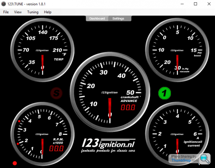
This is the real-time Advance and Retard function
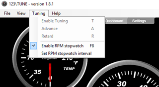
Whilst the engine is running pressing A advances the Ignition timing and R retards it (In real-time).
Whilst idling, I increased the ignition advance from my original setting of 14Degrees BTDC until the engine idled smoothly. This was easily done by ear until I found 19 Degrees BTDC gave me a sweet tick-over and the car stopped rocking.
Steve's record above also shows how the Stepper Motor adjusted according to tested changes.
Cheers
MPO
Edited by MPO on Tuesday 12th July 11:35
Peter66 said:
Hi Steve and MPO,
Very interesting findings. I also have a 123ignition on my 4.3 Precat and wanted to optimize the vacuum advance curve. Would it be possible to share the optimal advance curve? I remembered from MPO's past postings that the standard curve was not good. I think I have the standard 123 setting and have small throttle hesitation issues.
Steve does your improved 14CUX EPROM require a different 123 ignition curve setting or can both fuel and ignition settings be optimized independently?
Thanks for all your great work.
Best,
Peter
Hi PeterVery interesting findings. I also have a 123ignition on my 4.3 Precat and wanted to optimize the vacuum advance curve. Would it be possible to share the optimal advance curve? I remembered from MPO's past postings that the standard curve was not good. I think I have the standard 123 setting and have small throttle hesitation issues.
Steve does your improved 14CUX EPROM require a different 123 ignition curve setting or can both fuel and ignition settings be optimized independently?
Thanks for all your great work.
Best,
Peter
I note you have had your 123 Ignition Tune for a little while now. Nice one!
Is it just the Vacuum advance curve you’re looking to adjust?
Also, did you ever get your 123 Tune tweaked on a Dyno?
Cheers
MPO
MPO fascinating results from Ignition123 but those advance figures for idle seem a bit high, also were you after some vacuum and valve timing numbers recently? If so I found these which might be of interest, I'm not sure as they're for a V8 Defender with carbs but might be valid as a start point:
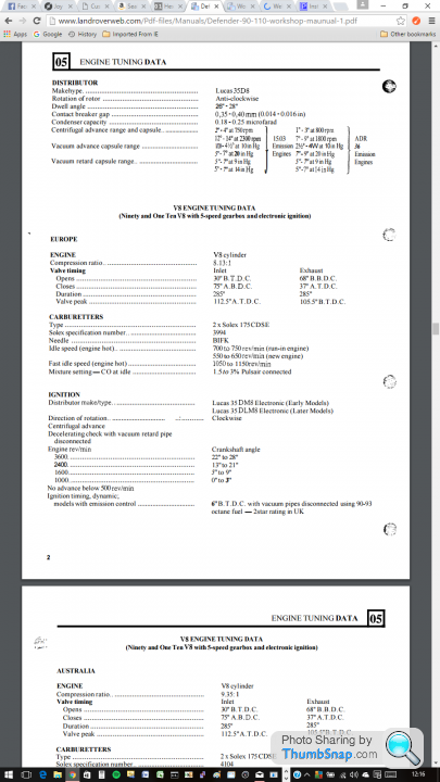
Gassing Station | Griffith | Top of Page | What's New | My Stuff