Instructions to change fuel maps on 14CUX Griffith, Chimaera
Discussion


CGCobra said:
Hi Steve
Sorry not to have been back sooner but been very busy last week and that looks set to continue until about mid November. I'll try and do a run with your new AFR logger at the weekend weather permitting and let you know how it goes.
No rush, it's given me a chance to also fixed my merger so it now works with AFR date and time records like RoverGauge plus I've stopped the zero AFR records top and bottom. I welcome your interest as it’s motivated me to fix some of the smaller annoying issues I never bothered fixing for myself, thanks.Sorry not to have been back sooner but been very busy last week and that looks set to continue until about mid November. I'll try and do a run with your new AFR logger at the weekend weather permitting and let you know how it goes.
SteveSprint, & others,
Hope you don't mind some simple questions. I had a guy make me a version of the "TVR 430 Precat and 450 CAT based on LR R3652 with Extended Fuel Table to 6250RPM" chip from your pages. I have a 4.6L in my MGB and have a NAS ECU and stock O2 sensors and a Wideband also. Issue I am having is RoverGauge comes up with no Codes except "Tune Resistor Out of Range" and then I end up in Map 0 which comes up with low RPM etc. But the Lambda's both show and are move in Short and Long term.
If i download the Chip via Rover Gauge and run the 14CUX Toolkit, Copy Rom 1 to Rom 2 I get a file that looks correct. But where is Map 0 located? How do I get out of it if there are no codes?
Thanks for the help,
Mike
Edited by Mjstemp1 on Wednesday 19th October 20:17
Further to my above questions, I have a battery disconnect and this has been toggled to no effect on the Tune Map.
Edit.
So looking at Address 47C1 I see that the Tune Resistor Enable is 00 in the new chip and my stock NAS 3.9L 3652 it was FF. Does this imply I either add a 3900 Ohm from Pin 5 of the ECU to ground or make up a new chip after changing this Address from 00 to FF?
Edit.
So looking at Address 47C1 I see that the Tune Resistor Enable is 00 in the new chip and my stock NAS 3.9L 3652 it was FF. Does this imply I either add a 3900 Ohm from Pin 5 of the ECU to ground or make up a new chip after changing this Address from 00 to FF?
Edited by Mjstemp1 on Wednesday 19th October 22:43
Ok so I guess I can now answer my own questions. Never thought I would say there is too much info now on the 14CUX system! Dan, Colin Steve, Mark thanks a million for all your work. Tried to get the MGB V8 folks in US on to this but seems all they want is MS.
So my answer was found here:
http://www.stevesprint.com/remap-14cux/addresses.h...
Wish I had found that before having a chip burned. Have my own programmer on the way from China but takes at least 1.5 mn to get into Canada, yes our customs agents are SLOW!
May be we could get a spot to store all this info without going through 55 pages and multiple sites?
Mjstemp1 said:
Hope you don't mind some simple questions. I had a guy make me a version of the "TVR 430 Precat and 450 CAT based on LR R3652 with Extended Fuel Table to 6250RPM" chip from your pages. I have a 4.6L in my MGB and have a NAS ECU and stock O2 sensors and a Wideband also. Issue I am having is RoverGauge comes up with no Codes except "Tune Resistor Out of Range" and then I end up in Map 0 which comes up with low RPM etc. But the Lambda's both show and are move in Short and Long term.
Hi and Welcome, sorry for the delayed response.I’m pleased you've found my 14CUX webpages and answered your own questions, it sounds like you know what you are doing. Hopefully you also found this useful wiring diagram www.remap-14cux.info/14CUX-Wiring.pdf
As you are running stock O2 sensors my "TVR 430 Precat and 450 CAT based on LR R3652 with Extended Fuel Table to 6250RPM” is a good starting point especially if you rev past 5,500rpms. If not, you could try TVR’s OEM map “TVR Chimaera 450 CAT (R2967)” because the Chimaera 450 engine is actually a 4.6 but with 4.0 pistons to increase the compression ratio. Please let me know how you get on as I plan to revisit my "TVR 430 Precat and 450 CAT based on LR R3652 with Extended Fuel Table to 6250RPM” to improve the coasting/slowing down idle.
What wideband sensor do you have? I’ve written a small program that captures my Innovate LC2 wideband AFR readings and outputs to a log file with the system time against each reading, I then merge the AFR reading by the system time with the RoverGauge log to show the AFR against each active fuel table row and column in the log. I finally create an Excel pivot table that shows the AFR for each cell in the fuel table as on the previous page. I maybe able to adapt my AFR logger to work with your wideband sensor, but no promises.
Mjstemp1 said:
So looking at Address 47C1 I see that the Tune Resistor Enable is 00 in the new chip and my stock NAS 3.9L 3652 it was FF. Does this imply I either add a 3900 Ohm from Pin 5 of the ECU to ground or make up a new chip after changing this Address from 00 to FF?
Correct, to run map 5 you need either a 3900 ohms across pin 5 & Ground or you can force map 5 by setting 47C1 to FF as in the NAS tunes. (Dan informed us NAS vehicles don’t have pin 5’s connector in the plug & loom).Mjstemp1 said:
If i download the Chip via Rover Gauge and run the 14CUX Toolkit, Copy Rom 1 to Rom 2 I get a file that looks correct. But where is Map 0 located? How do I get out of it if there are no codes?
I’m sure you’ve realised down loading via RoverGauge give you one copy then need duplicating to flash back to a chip.
I’m sure you now realise Map 0 starts at chip offset 00 or 4000 and is the default map when there is no tune resistor, but its best you force map 5 with either of the methods you correctly worked out.I’m sure you’ve realised down loading via RoverGauge give you one copy then need duplicating to flash back to a chip.
Mjstemp1 said:
May be we could get a spot to store all this info without going through 55 pages and multiple sites?
I plan to update my 14CUX web pages this winter and I’ve registered the domain www.remap-14cux.info . In the mean time should you require any further information please do not hesitate to contact us again.Good Luck and Enjoy,
Steve Sprint
Steve,
Thanks for the replys. Was able to get the 3900 ohm resistor installed and working now in Map 5. Having a significant lean stumble based on the AEM wideband when I roll into the throttle around 2000 rpm. Full throttle also is leaner than I would have thought at around 13. Have to figure out how to dataLog from the AEM gauge. Then will try merging etc the files.
I also have an issue with my road speed sensor. VDO gauge with hal sensor and speedo works but ECU not getting signal, have to measure what's coming from the wire. Would lack of road speed cause lean stumble?
Mike
Mjstemp1 said:
Steve,
Thanks for the replys. Was able to get the 3900 ohm resistor installed and working now in Map 5. Having a significant lean stumble based on the AEM wideband when I roll into the throttle around 2000 rpm. Full throttle also is leaner than I would have thought at around 13. Have to figure out how to dataLog from the AEM gauge. Then will try merging etc the files.
I also have an issue with my road speed sensor. VDO gauge with hal sensor and speedo works but ECU not getting signal, have to measure what's coming from the wire. Would lack of road speed cause lean stumble?
Mike
Did your ECU loom already have the wire to pin 5 for the tune resistor?Thanks for the replys. Was able to get the 3900 ohm resistor installed and working now in Map 5. Having a significant lean stumble based on the AEM wideband when I roll into the throttle around 2000 rpm. Full throttle also is leaner than I would have thought at around 13. Have to figure out how to dataLog from the AEM gauge. Then will try merging etc the files.
I also have an issue with my road speed sensor. VDO gauge with hal sensor and speedo works but ECU not getting signal, have to measure what's coming from the wire. Would lack of road speed cause lean stumble?
Mike
How lean and how much throttle????
You shouldn't run lean at 2,000rpm while running closed loop unless you've run out of lambda trim or the throttle is more than 40% or the engine temperature is below 50 deg c which both force open loop. The lambda trims should fluctuate the AFR around 14.7 and gradually decay up to 3,400 rpm.
Here’s the results of my Griff 4.3 this weekend running R3652 map 5 TVR 450CAT, you can see on full load my 430 can’t reach the bottom row of the fuel table and runs rich on full load, but interestingly it drives surprisingly well.

According to Des Hammill “How To Power Tune Rover V8” 13 AFR is best for fully open throttle between Max torque & Max Power, Des Hammill says the following AFRs are proven.
13.5 Idle (for smooth slow speed)
12.5 Accelerating from stand still
13.0 between Max torque & Max Power
15.4 Economy Cursing (Max)
If your AEM wideband outputs human readable AFR readings then try this version of my AFRLogger with the timelog parameter “AFRLogger timelog” but you’ll need to know and select your AEM connection settings from the Settings drop down menu. Its not the finished product but may help identify what’s involved.
www.remap-14cux.info/AFR_Logger.zip
If not you could try taking a video clip of RoverGauge and your AEM Gauge together while driving and avoid sudden throttle movements, or you could bribe a passenger to note down the AFR readings.
We know the road speed has no effect on AFR and the lack of a road speed sensor will cause the engine to stall while slowing down, but not 100% sure if “the lack of road speed cause lean stumble”.
You can see from my favourite wiring diagram the speed signal should be pulsed +12v on pin 6 preferably with diode protection. You'll need roughly 3 or 4 pulses per prop-shaft revolution and for best results the 0 volts & 12v pulses should be similar duration.
Steve
RV8 - I'm doing my bit for global warming
Steve & Mark,
Thanks again for your input. I was still thinking for WOT I should be seeing AFR of 12.5. I am getting about 13 and it does drop a bit as RPM increase. Just as you mention elsewhere Steve, 2000 rpm ~13.2 to 12.7 around 5000 rpm.
Couple of further questions on Datalogging the AEM gauge. Seems it only has analog out put with two wires and 0-5V. What I don't know is what sort of cable I would need for this to input to a USB. Would it be another of the TTL-USB like the RG cable? Their direction are a little vague!
"[WHITE – The WHITE wire should be connected to the Lambda + input on the
EMS or the analog + input on a similar device.
BROWN – The BROWN wire should be connected to the Lambda – input or the
analog – input. If the EMS or similar device does not have a – input, the BROWN wire
should be connected to a sensor ground. If no sensor ground is available, the BROWN
wire should be connected to a power ground. Note: The BROWN wire must be
connected in order to get correct readings from the analog output.]"
As to the surge/hiccup as I roll on the throttle, not sure what is causing it now. I do not see anything on my TPS that looks out of place. I recall having this also happen when on Map 0. AFR goes lean and then its fine as I continue. Fuel,trim in RG long term is -20 &-40. Plotted Short term trim and at 2000 rpm I get lots of +250 on one side and -100 on the other.
Thought could be ignition but then it should go rich should it not. Could it be a loss of RPM signal? But then I should see it in the log also.
Another basic question, RG fuel map, the engine load is coming from TPS or AFM or a combination of the two?
Mike
Edited by Mjstemp1 on Tuesday 25th October 02:29
Mjstemp1 said:
Couple of further questions on Datalogging the AEM gauge. Seems it only has analog out put with two wires and 0-5V. What I don't know is what sort of cable I would need for this to input to a USB. Would it be another of the TTL-USB like the RG cable? Their direction are a little vague!
"[WHITE – The WHITE wire should be connected to the Lambda + input on the
EMS or the analog + input on a similar device.
BROWN – The BROWN wire should be connected to the Lambda – input or the
analog – input. If the EMS or similar device does not have a – input, the BROWN wire
should be connected to a sensor ground. If no sensor ground is available, the BROWN
wire should be connected to a power ground. Note: The BROWN wire must be
connected in order to get correct readings from the analog output.]"
Sadly, doesn’t sound like a serial data output that can be connected directly to a computer via a USB cable, you maybe able to connect it to a computer via a data logger."[WHITE – The WHITE wire should be connected to the Lambda + input on the
EMS or the analog + input on a similar device.
BROWN – The BROWN wire should be connected to the Lambda – input or the
analog – input. If the EMS or similar device does not have a – input, the BROWN wire
should be connected to a sensor ground. If no sensor ground is available, the BROWN
wire should be connected to a power ground. Note: The BROWN wire must be
connected in order to get correct readings from the analog output.]"
Mjstemp1 said:
As to the surge/hiccup as I roll on the throttle, not sure what is causing it now. I do not see anything on my TPS that looks out of place. I recall having this also happen when on Map 0. AFR goes lean and then its fine as I continue. Fuel,trim in RG long term is -20 &-40. Plotted Short term trim and at 2000 rpm I get lots of +250 on one side and -100 on the other.
Another basic question, RG fuel map, the engine load is coming from TPS or AFM or a combination of the two?
How lean does the AFR go?Another basic question, RG fuel map, the engine load is coming from TPS or AFM or a combination of the two?
While the throttle is steady or moving slowly the engine load only comes from the AFM, the active row does momentarily jump further down than normal when the throttle opens rapidly and momentarily jumps higher than normal when closing rapidly.
Does the active row change smoothly around at 2,000rpm?
That output signal will be a 0 - 5 volt variable voltage depending on AFR. You could go to he effort of converting it to a digital signal that a PC would understand and then trying to convert that back to AFR, but to be honest you are better off putting a cellophane over the PC screen / map and getting a passenger to mark the cells that are rich or lean with a pen against the gauge reading. Primitive but works well enough. The bit about AFR for maximum power can be deceptive, as you have to take the fuel enrichment into account that occurs when you floor the throttle, as this is in addition to what the fuel map is dumping in as a base setting. An AFR of 12.5: is with this enrichment added for a few seconds only, you dont want it that rich under a static full load condition.
Edited by blitzracing on Wednesday 26th October 11:41
Thanks again gents!
Lean stumble is a jump from around AFR of 15 to above 17, feels like motor cut out so the gauge may not be dropping enough actually ! Need to get a passenger to help video, plot etc.
Frustrating on the AEM Analog gauge as they work great as a gauge, data logging leaves a bit to be desired unless feeding into a MS or other ECU. There are modules that could be added to capture and input the 0-5V signal, low end are around $50 USD for any one else with this issue.
Mjstemp1 said:
Thanks again gents!
Lean stumble is a jump from around AFR of 15 to above 17, feels like motor cut out so the gauge may not be dropping enough actually ! Need to get a passenger to help video, plot etc.
Frustrating on the AEM Analog gauge as they work great as a gauge, data logging leaves a bit to be desired unless feeding into a MS or other ECU. There are modules that could be added to capture and input the 0-5V signal, low end are around $50 USD for any one else with this issue.
Try and reproduce the lean stumble to a RoverGauge log and check if any of the settings suddenly change, for exampleLean stumble is a jump from around AFR of 15 to above 17, feels like motor cut out so the gauge may not be dropping enough actually ! Need to get a passenger to help video, plot etc.
Frustrating on the AEM Analog gauge as they work great as a gauge, data logging leaves a bit to be desired unless feeding into a MS or other ECU. There are modules that could be added to capture and input the 0-5V signal, low end are around $50 USD for any one else with this issue.
mafPercentage
currentFuelMapRow
currentFuelMapCol
lambdaTrimOdd
lambdaTrimEven
pulseWidthMs
The more unnecessary sensors you turn off in "Options|Edit Settings" the more log records you'll get per second.
Good Luck
Steve
Steve,
The more I play the further I get confused! I have moved to Map 2 to try and remove any thing to do with the Lambda feedback. Still have stumble or miss at 2100 to 2800 rpm at 76, A7 and A0, cells are posted below.
As you can see in the image I have three different table of the same Map 2.TunerPro keeps showing different numbers compared to RG and HxD editior. At top load end they match up but are off at low to mid load points points.
Is there a newer version of XDF for the 14CUX?
The one from this page is different from the true map shown in RG. I assume RG is correct.
http://www.stevesprint.com/remap-14cux/gadgets.htm...
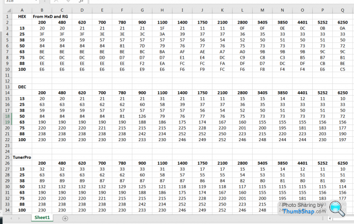
So what am I missing here?
The points that I am getting a hickup at are 2100 to 2800 rpm at 76, A7 and A0.
The more I play the further I get confused! I have moved to Map 2 to try and remove any thing to do with the Lambda feedback. Still have stumble or miss at 2100 to 2800 rpm at 76, A7 and A0, cells are posted below.
As you can see in the image I have three different table of the same Map 2.TunerPro keeps showing different numbers compared to RG and HxD editior. At top load end they match up but are off at low to mid load points points.
Is there a newer version of XDF for the 14CUX?
The one from this page is different from the true map shown in RG. I assume RG is correct.
http://www.stevesprint.com/remap-14cux/gadgets.htm...
So what am I missing here?
The points that I am getting a hickup at are 2100 to 2800 rpm at 76, A7 and A0.
Mjstemp1 said:
Steve,
So what am I missing here?
The points that I am getting a hickup at are 2100 to 2800 rpm at 76, A7 and A0.
RoverGauge is Hexidecimal, Tunerpro is Decimal by default, but its switchable in one on the menus. The numbers from 0-9 are the same in both, but 10 becomes A, 11- B, 12 -C, 13-D, 14-E, 15-F. So what am I missing here?
The points that I am getting a hickup at are 2100 to 2800 rpm at 76, A7 and A0.
Assuming the fuel table is not bouncing around with wild values at the point of the misfire (I cant see why it should) Id be looking at ignition- the HT required at different engine loads and throttle openings does vary a lot, so if the HT is low it will misfire under certain engine conditions. This will give a very lean reading from the lambda probes as they measure spare oxygen in the exhaust, and un burnt mixture is oxygen rich, just like a lean mixture.
Edited by blitzracing on Saturday 5th November 18:31
Edited by blitzracing on Saturday 5th November 18:33
Hi,
I have just bought an MG with a 14CUX EFI. I also had some hesitation on accelerating hard at different rpm. One flat spot was around 1700 another in the upper 2000s. After this they were gone at higher revs. At least I didnt noticed them. A new Bosch coil, new HT leads and a more advanced ignition timing of at least 11 degrees at idle cured these problems.
If you allow I would like to ask another question to the experts:
Is it a bad idea to backup the ROM checksum at battery backed up location $54 which seems unused in order to reset the long term lambda trims if an emulated ROM is changed ? I am using an Ostrich 2 emulator and am a little annoyed by ever reconnecting the car battery. I tried my first code change like this and it seems to work:
ldab CHECKSUM_FIXER ;start of my code
cmpb $54 ;potential unused battery backed up ram location
beq .clr_int_ram ;ROM not changed
stab $54
ldd #$8000 ;reset long term trims
std secondaryLambdaR ;as when ECU was disconnected from power suppply
std longLambdaTrimR
std secondaryLambdaL
std longLambdaTrimL ;end of my code
;----------------------------
; Clear internal memory
;----------------------------
.clr_int_ram clra
ldx #$0055 ; *** Zero Memory $54 to $FA ***
ldab #$A5
.zeroRAM_0054 staa $00,x
inx
decb
bne .zeroRAM_0054 ; *** End Zero Memory ***
If it evolves satisfactory I would encapsulate the later original battery ram clear sequence in a subroutine. Possible the stepper motor value should be resetted too . The routine would do that also.
Cheers
Mark L
Mark,
Fully understand the Hex. If you look at the table you will see that I converted the RG map to dec. My question is why are they different between RG and TunerPro when both are in December? A few years back others had similar findings and it was the XDF for the 14 CUX in TunerPro. Trying figure out if there is a newer XDF that I don't have.
As to ignition I think that may by my cause. It's not a Rover distributor, Buick with Pertronix II.
Mjstemp1 said:
Mark,
A few years back others had similar findings and it was the XDF for the 14 CUX in TunerPro. Trying figure out if there is a newer XDF that I don't have.
Mark, A few years back others had similar findings and it was the XDF for the 14 CUX in TunerPro. Trying figure out if there is a newer XDF that I don't have.
Sorry for the delay, life keeps me very busy and I wouldn't have it any other way.
I remember and won't mention any names, they admitted off air they were comparing different maps, I'm certainly not suggesting that is your issue. In TunerPro right click on “TunerPro MAP 2 FUEL TABLE – Green” and check Address is 0x4379, then check the table in the bin file at hex 4379 with HexEdit. Do you have an Ostrich emulator and downloaded the bin to TunerPro. If you email me a full screen shot of your TurnerPro & RoverGauge I'll try and help you.
Here’s the latest TunerPro Defination file, although it contains the following extra scalars & table I doubt it will fix your issue.
www.remap-14cux.info/TunerPro-xdf.zip
Tested and work
Coasting Idle Hold Up - increase to lower lingering idle
Cranking Idle Adjust - Adjusts cranking idle across the whole temp range
Cranking Idle Table by Temperature (See notes in TunerPro)
Tested and didn’t see any noticeable difference
Map 2 – Warm Up Threshold
Map 2 – Warm Up Temp Threshold (77 Degc)
Map 2 – Full Load Additive
Map 2 – Deceleration Gain
Gassing Station | Griffith | Top of Page | What's New | My Stuff