Instructions to change fuel maps on 14CUX Griffith, Chimaera
Discussion


Today I visited Surry Rolling Road armed with Robert’s TunerPro definition files and Joolz’s Ostrich which all worked faultlessly. I used RoverGauge to see the active cell and the Ostrich to make real time changes. Roberts TunerPro definition files can be downloaded from TunerPro’s website (link below) and I must thank Joolz for all his support and mapping advice.
http://www.tunerpro.net/download/bindefs/Other/14C...
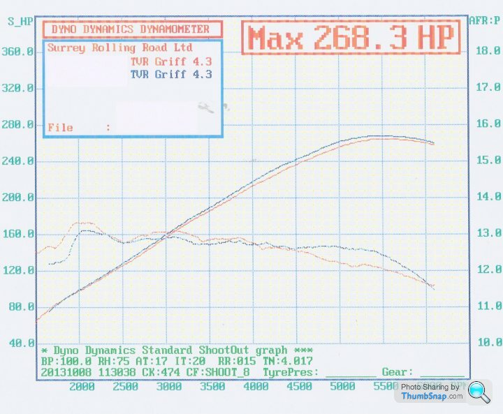
The first run in red proved I’ve successfully copied the complete map data structure from my old precat revision R2422 into TVRs later revision R2967.
I then reduced the bottom entries in the last two columns and had another run. This didn’t change the AFR past 5,500 as the active cell didn’t run along the bottom row so I also changed the 2nd to last row, see blue line. As a result I decided to change the ‘Calc fuel map row’ from 91 to B2, which successfully moved the active cell to bottom row and improved the fuelling past 5,500 rev. However this effectively shifted the entire table up a row and you can see the results in the second graph. I called it a day as I’d proved I can change the AFR and I needed to consider the results and options offline.
Can any 430 Owner with RoverGauge please confirm if the active cell hits your bottom row, you can test safely with data logging turned on.
Dan - Is ‘Calc fuel map row’ a smooth sliding scalar or is it stepped? I ask because I’ve noticed TVR 4.3, TVR4.5 & TVR500 all are 91 and TVR 400’s and Land Rover 3.9’s are B2.
Thanks for everyone’s help, support and encouragement.
Cheers, Steve

http://www.tunerpro.net/download/bindefs/Other/14C...
The first run in red proved I’ve successfully copied the complete map data structure from my old precat revision R2422 into TVRs later revision R2967.
I then reduced the bottom entries in the last two columns and had another run. This didn’t change the AFR past 5,500 as the active cell didn’t run along the bottom row so I also changed the 2nd to last row, see blue line. As a result I decided to change the ‘Calc fuel map row’ from 91 to B2, which successfully moved the active cell to bottom row and improved the fuelling past 5,500 rev. However this effectively shifted the entire table up a row and you can see the results in the second graph. I called it a day as I’d proved I can change the AFR and I needed to consider the results and options offline.
Can any 430 Owner with RoverGauge please confirm if the active cell hits your bottom row, you can test safely with data logging turned on.
Dan - Is ‘Calc fuel map row’ a smooth sliding scalar or is it stepped? I ask because I’ve noticed TVR 4.3, TVR4.5 & TVR500 all are 91 and TVR 400’s and Land Rover 3.9’s are B2.
Thanks for everyone’s help, support and encouragement.
Cheers, Steve
Edited by stevesprint on Monday 21st October 23:08
stevesprint said:
Dan - Is ‘Calc fuel map row’ a smooth sliding scalar or is it stepped? I ask because I’ve noticed TVR 4.3, TVR4.5 & TVR500 all are 91 and TVR 400’s and Land Rover 3.9’s are B2.
Steve, are you talking about the value at fuel map offset 0x10A that is used from RAM location 0x200A? If so, yes, it's a multiplier and any value is legitimate (my 93 RRC has value 0xB9). Software limits the result of the multiplication so you can't get into trouble by going beyond the table limits. The range of the result is 0x00 (1st row) to 0x70 (last row).Also, I should mention again that there is a full byte that addresses both the row and column of the fuel map. Usually the fueling point is somewhere between 4 cells on the map. Software does a weighted linear interpolation between the 4 values to calculate a 16-bit fueling value. RoverGauge simplifies this by just highlighting the closest cell to the actual fueling point. So, even though the bottom row was never highlighted, it may have contributed to the fueling calculation. For example, if the row index was 0x67, the second last row would be highlighted, but the last row would be contributing 7/16 to the calculation.
stevesprint said:
Could RoverGauge read the complete bytes change Bit 4 and send the complete byte back?
Steve, you read my mind on this one. RoverGauge could have a button to do a read/modify/write cycle to alter only this bit and, if I understood the code correctly (a big IF), it should allow us to force closed maps to run open.stevesprint said:
I’m thinking if Bit 5 is set when the revs exceed the value stored at 0xC0A7 in the PROM would changing the value at 0xC0A7 to 500 force open loop above 500 revs. Hummm, that’s strange C0A7 in a few PROM I have is 08 9D and that’s 2205 in decimal, I must be having another blonde moment.
Remember the conversion value? Divide 7,500,000 by 2205. Yes, lowering the RPM cutoff should work.stevesprint said:
Would it be possible for RoverGauge to set/unset this address in memory to force open loop on and off.
No, this location (0xC099) is in ROM, so RoverGauge can't change it.danbourassa said:
Steve, are you talking about the value at fuel map offset 0x10A that is used from RAM location 0x200A? If so, yes, it's a multiplier and any value is legitimate (my 93 RRC has value 0xB9). Software limits the result of the multiplication so you can't get into trouble by going beyond the table limits. The range of the result is 0x00 (1st row) to 0x70 (last row).
Arrr yes, I see it’s B2 for non cat and B9 for cat, interesting. Thanks for the clear explanation I understand.danbourassa said:
Also, I should mention again that there is a full byte that addresses both the row and column of the fuel map. Usually the fueling point is somewhere between 4 cells on the map. Software does a weighted linear interpolation between the 4 values to calculate a 16-bit fueling value. RoverGauge simplifies this by just highlighting the closest cell to the actual fueling point. So, even though the bottom row was never highlighted, it may have contributed to the fueling calculation. For example, if the row index was 0x67, the second last row would be highlighted, but the last row would be contributing 7/16 to the calculation.
I see and once again thanks for the re-mapping lesson. Credit to Joolz (Spitfire4) as he thought it might be weighted linear interpolation. Does RoverGauge always highlight the top cell of the 4 cells contributing?stevesprint said:
I see and once again thanks for the re-mapping lesson. Credit to Joolz (Spitfire4) as he thought it might be weighted linear interpolation. Does RoverGauge always highlight the top cell of the 4 cells contributing?
No, RoverGauge highlights the closest cell to the fueling point. If the row index was 0x69 (instead of the 0x67 example earlier) then a last row cell would be highlighted.danbourassa said:
Remember the conversion value? Divide 7,500,000 by 2205. Yes, lowering the RPM cutoff should work.
Dan I certainly do but I thought that was only for RPM limit.danbourassa said:
No, this location (0xC099) is in ROM, so RoverGauge can't change it.
Sorry, yes of cause, therefore would it work if we changed it on the PROM?stevesprint said:
Dan I certainly do but I thought that was only for RPM limit.
RPM related values in the 14CUX software are usually in spark period (2 uSec units) instead of actual RPM. This is always true for higher RPMs since the spark period to RPM calculation is bypassed at about 2000 RPM.stevesprint said:
Sorry, yes of cause, therefore would it work if we changed it on the PROM?
Yes, it should.stevesprint said:
Dan - Do you know what addresses $C4231 to $C423E are for? I’ve been comparing bins, as you do, and I’m starting to think they could be for the road speed limit. It's only a hunch so I could be completely wrong.
Thanks Steve
Steve, do you mean $C231 to $C23E? This is a special high-rpm/high-throttle ADC control table. When engine speed is over 4185 RPM and throttle is over 70%, software uses this table in place of the normal ADC table for the current fuel map. This table, as you must have noticed, is heavily loaded with road speed measurements. Lucas had a lot of trouble with the road speed limit and I think this was just another patch to try to make things work correctly. The problem is that patches like this cause other problems that lead to more patches.Thanks Steve
The actual limit is in the code section of the PROM, not the data section. Look at the value at $EA41. If it's $C4, this is the limit in KPH (196 KPH or 122 MPH). This section of code sets a bit which normally causes fueling to be cut off. This fuel cutoff code is missing in TVR code, but a lot of clock cycles are wasted measuring road speed anyway. The sad thing is that this is being measured unnecessarily at a time when the microprocessor is nearly maxed out and can least afford it.
DanYourTheMan said:
For example, if the row index was 0x67, the second last row would be highlighted, but the last row would be contributing 7/16 to the calculation.
If the last row (7) contributes 7/16 because the lower nibble equals 7 I guess row 6 would contribute the remaining larger proportion of 9/16, which now makes sense.DanYourTheMan said:
No, RoverGauge highlights the closest cell to the fuelling point. If the row index were 0x69 (instead of the 0x67 example earlier) then a last row cell would be highlighted.
I see, I see, that’s really neat how the ECU code moves SMOOTHLY around the fuel table while RoverGauge rounds 67 down to row 6 and rounds 69 up to the bottom row 7. To confirm I understand, when 6A the last row (7) would contribute a larger portion of 10/16 and row 6 would contribute a small portion of 6/16. It’s amazing how much maths an 8-bit processor can handle in a short space of time. I see from Colin’s notes the column index upper nibble runs from 0x0 thru 0xF so I guess the column index lower nibble behaves the same way as the row lower nibble. If so, that must mean column 14 is taken into account until the RPM are 5502 (F0) and above. Once past 5502 rpm (F0) I guess only the last column (15) is taken into account and any further column index rise i.e. from F0 to FF is ignored. Luckily my peek power is at 5500rpm.
Thanks for your patience with me I really appreciate it especially when I’m slowing getting my head around the concepts and then you though more challenges at me. I could do with a good website to read up on the concepts so I wouldn't have to ask so many question.
Thanks again and Cheers from Steve (Grateful) Sprint
Edited by stevesprint on Sunday 13th October 12:28
Robert
Now Dan has taught me the finer thing in life, like ‘weighted linear interpolation’, could this smoothing between the cells be what I’m seeing in TunerPro when the active cell highlight moves between 2 cells and not exactly on a cell? If so it would be really good to overcome the errors on the TunerPro serial link. If you don’t mind I’ll email Mark @ TunerPro to see if he has any suggestions. I hope he doesn’t ask me anything to complicated, as I don’t totally understand the ADX Header Data and the TableMacro.
I hope you have sorted your running problems.
Cheers Steve
The values that tunerpro is getting from the ecm are integers, so it shouldn't be interpolating.
I'm still sorting out my running issues. I thought it was a cracked y-pipe so I replaced that and no change. Rovergauge is showing 100% on long term fuel trim for both banks. I'm going to hook the wideband up tomorrow and see if the AFRs creep up after a ECM reset.
I'm still sorting out my running issues. I thought it was a cracked y-pipe so I replaced that and no change. Rovergauge is showing 100% on long term fuel trim for both banks. I'm going to hook the wideband up tomorrow and see if the AFRs creep up after a ECM reset.
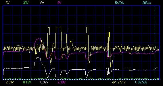
Heres a plot that may be of interest with the wideband with a TVR 3.9 chip. The AFR gauge will bounce around all over the place as the lambdas do there work, and it makes it pretty difficlt to see whats really going on. Its not until I data logged the output with a relatively slow scan rate you can really see whats going on. The plot colours are:
white - throttle pot
Purple - AFM output
Yellow A/F ratio- lambda output
You can see under steady state the ECU tries to average out the mixture with a mid point voltage of 2.15 volts thats about 14.3:1 AF ratio. You can see the sharp fuel cut off on the overrun (lean mixture gives a higher voltage) and the point where the ECU loose control of the mixture momentarily as conditions change.
Edited by blitzracing on Monday 14th October 18:44
Hello everyone. I've been following the post for a while now and I'm ready to start experimenting with it. I have a few ECU's laying around, blank EPROM's, a lot of patience and a "sligtly" modified Disco I. All my ECU's are R3526 or R3360. I would like to start with a later (maybe R3652)tune and work from there. Is there a repository of stock and modified tunes somewhere? Why don't we make one?
Thanks, Karls
Thanks, Karls
Hi Karls,
Welcome to this project. You can find R3652 under the PROMs directory here:
https://drive.google.com/?tab=wo&authuser=0#fo...
Welcome to this project. You can find R3652 under the PROMs directory here:
https://drive.google.com/?tab=wo&authuser=0#fo...
I just uploaded a few flowcharts to the directory I mentioned above. They are done in PowerPoint but Google allows viewing online. They aren't perfect and I'm sure there will be future revisions, but I think they might be good enough to be useful for our collective effort to understand the 14CUX. Colin reviewed them and he didn't find any obvious blunders. I estimate that the flowcharts only cover about half the code so far. Making them actually helped my understanding but there are still blocks of code that I don't have a clue about. There is also a diagram showing what I think is inside the PAL. I plan to do more when I have time. I hope someone finds them useful.
danbourassa said:
I just uploaded a few flowcharts to the directory I mentioned above. They are done in PowerPoint but Google allows viewing online. They aren't perfect and I'm sure there will be future revisions, but I think they might be good enough to be useful for our collective effort to understand the 14CUX. Colin reviewed them and he didn't find any obvious blunders. I estimate that the flowcharts only cover about half the code so far. Making them actually helped my understanding but there are still blocks of code that I don't have a clue about. There is also a diagram showing what I think is inside the PAL. I plan to do more when I have time. I hope someone finds them useful.
Very useful Dan, many thanks.danbourassa said:
I just uploaded a few flowcharts to the directory I mentioned above. They are done in PowerPoint but Google allows viewing online. They aren't perfect and I'm sure there will be future revisions, but I think they might be good enough to be useful for our collective effort to understand the 14CUX. Colin reviewed them and he didn't find any obvious blunders. I estimate that the flowcharts only cover about half the code so far. Making them actually helped my understanding but there are still blocks of code that I don't have a clue about. There is also a diagram showing what I think is inside the PAL. I plan to do more when I have time. I hope someone finds them useful.
Dan Thanks for the bins & flow charts, you are certainly making amazing progress, it won't be long until you compile/assemble your own version. Do you really think one day you'll implement Roberts idea to input a wideband Lambda sensor 0-5v signal into the heated screen input? I'm planning to install a wideband lambda sensor over the winter and it would be the ultimate solution.
Thanks for showing us inside the 14cux, Cheers, Steve
Gassing Station | Griffith | Top of Page | What's New | My Stuff