Instructions to change fuel maps on 14CUX Griffith, Chimaera
Discussion


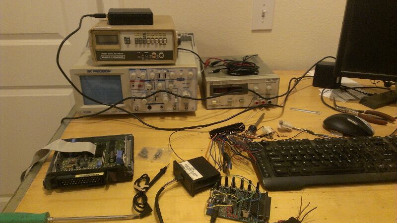
Well I got all of my stuff out of storage from the last time I messed with this. I'll be wiring up the test bench this week and hopefully I'll be able to monitor real pulse width changes based and get some sort of rough formula to help with tuning.
Does anyone know how the heated windshield or a/c inputs affect the strategy? Is there a different idle table, an idle addition, or is it something totally different?
some nerd eye candy:
Does anyone know how the heated windshield or a/c inputs affect the strategy? Is there a different idle table, an idle addition, or is it something totally different?
some nerd eye candy:
robertf03 said:
Does anyone know how the heated windshield or a/c inputs affect the strategy? Is there a different idle table, an idle addition, or is it something totally different?
There are idle offset values stored in the data section of the ROM -- one each the screen heater, A/C compressor, and neutral gear (as opposed to drive/reverse gear.) In the R3652 code, the adjustments (16 bits each, apparently stored as RPM) are located here:$0159: Neutral gear (0x0064)
$015B: A/C compressor (0x0032)
$01E9: Screen heater (0x0000)
Note that the later revisions of the code set the screen heater idle adjustment to zero. Apparently Rover discovered that it didn't present enough of a load to warrant a higher idle speed.
robertf03 said:
Well I got all of my stuff out of storage from the last time I messed with this. I'll be wiring up the test bench this week and hopefully I'll be able to monitor real pulse width changes based and get some sort of rough formula to help with tuning.
Does anyone know how the heated windshield or a/c inputs affect the strategy? Is there a different idle table, an idle addition, or is it something totally different?
some nerd eye candy:
Is that a megasquirt stimulator spy there? Was going to suggest one of those for bench testing these things.Does anyone know how the heated windshield or a/c inputs affect the strategy? Is there a different idle table, an idle addition, or is it something totally different?
some nerd eye candy:

I notice that for my Range Rover Classic (with automatic transmission), the base idle RPM is in drive, not in park or neutral. When I shift from drive to neutral, RPMs pick up by the value stored in $0159 ($C159 with PROM in place) which is 0x0064 (or 100 RPM). So the target idle shifts between 600 and 700 RPM with a fully warmed engine. This is simulating the same behavior as older, carburetor engines where the torque convertor load was pulling down the engine speed. I don't know if there was a technical reason for this or if it was just giving the driver the feedback he expects.
Dan, Colin, anyone, the main program runtime flowchart shown on the BigTurbo site shows a routine ‘Correct fuel for battery volts’ and we seem to have something similar in 14CUX/RoverGauge, i.e. Main Voltage. Does anyone have any ideas on how, why and when the battery voltage value is factored into fueling control? Is it ‘low voltage level more fuel’ for instance? If it is, how does the firmware distinguish between increases in engine/electrical load and a failing battery?
Also it would be interesting to know how the interrupt scheme is set up for the 14CUX processor.
Edit: I think I might have found the answer to 'why' and that is to compensate for voltage supply fluctuations on the injectors and the subsequent changes in fuel flow. So the ECU keeps an eye on battery voltage and adjusts injector pulse width accordingly. So as a possible cause of overfueling could a battery in a poor state of charge be a prime candidate?
Edited by davep on Thursday 5th September 11:44
Dave,
The battery voltage is measured periodically in the main code loop the same way most things are monitored. Software tells the 16-channel Hitachi A to D converter (HD46508) to do an 8-bit conversion. The direct value is never stored but is then immediately converted, through a quadratic equation, into the value needed for the injector pulse. The equation models the flow changes due to voltage (for that injector type). Originally, the equation values were just hard-coded inline, so Colin and I assumed that all 14CUX units were the same. He solved the quadratic, using the equation we learned (or at least, he learned) in math class years ago. We got complaints from early RoverGauge users that the displayed voltage was inaccurate so we looked into it further.
Lucas moved the quadratic values to the data section at some point and they are not the same for all units. Lucas must have realized that these values are subject to change when the injector style changes (and they did change along the way).
As voltage drops, such as during cranking, the compensating addition to fueling value must rise. Here is an example from my 93 RRC.
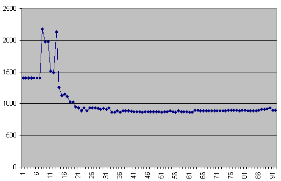
This shows ignition-on (the flat area), cranking (the large rise) and finally, the reduction due to a charging alternator. I'm sure that someone has changed from the early pintle style to the later disc style injectors. This might not be a good idea unless changing the ECU as well.
The battery voltage is measured periodically in the main code loop the same way most things are monitored. Software tells the 16-channel Hitachi A to D converter (HD46508) to do an 8-bit conversion. The direct value is never stored but is then immediately converted, through a quadratic equation, into the value needed for the injector pulse. The equation models the flow changes due to voltage (for that injector type). Originally, the equation values were just hard-coded inline, so Colin and I assumed that all 14CUX units were the same. He solved the quadratic, using the equation we learned (or at least, he learned) in math class years ago. We got complaints from early RoverGauge users that the displayed voltage was inaccurate so we looked into it further.
Lucas moved the quadratic values to the data section at some point and they are not the same for all units. Lucas must have realized that these values are subject to change when the injector style changes (and they did change along the way).
As voltage drops, such as during cranking, the compensating addition to fueling value must rise. Here is an example from my 93 RRC.
This shows ignition-on (the flat area), cranking (the large rise) and finally, the reduction due to a charging alternator. I'm sure that someone has changed from the early pintle style to the later disc style injectors. This might not be a good idea unless changing the ECU as well.
davep said:
Also it would be interesting to know how the interrupt scheme is set up for the 14CUX processor.
Dave, I'm glad you asked (you may regret getting me started on this). There are three execution "threads". One is the main loop, which in a sense is relegated to a background task and is what gets starved out at high RPM. The second is the spark interrupt which is triggered by the coil spark (through the external 6.8K resistor). This is really the heart of the processing. The third is the purge valve timer interrupt, which, I believe, never worked correctly.The Main Loop
When ignition is turned on initialization happens. This includes clearing RAM, initializing variables, setting up the serial port for 1MHz/128 (7812.5 baud), verifying trustworthiness of battery backed memory, dealing with stored fault codes, turning on the fuel pump for 255 counts, and more. The main loop is then entered.
This loop will run all day without interruption if you don't crank or start the engine. The fuel pump counter is decremented each time through and when the counter reaches zero, the pump is shut off. One important function of the main loop is to update all the relevant parameters. The Analog to Digital Converter (ADC) has 16 channels that are converted according to a table like this one in the fuel map data structure:
C7A9 : 87 86 02 03 84 02 8D 88 02 8B 80 85 81 8E FA FA
The left nibble tells the ADC to do either an 8 or 10 bit convert (0 = 10-bit). The right nibble is the channel number. The channel assignment list can be found near the bottom of this page:
http://alum.wpi.edu/~colinb/14cux.html
When the upper nibble is F, the list starts over.
The Purge Valve Interrupt
The MPU has three timers. Two are used to control the two injector banks. The third is used for the purge valve. There is a 16-bit value in memory (0x0096/97) that ranges between zero and 40,000 decimal. Driving conditions adjust this value. When the value is below 4000, the purge valve is OFF. When the value is above 29000, the purge valve ON. When the value is between these two limits, the purge valve is pulsed by the memory value in microseconds. This is where I have a problem. To send a 4 millisecond pulse to a solenoid valve controlling fluid and expect something useful to happen goes against my intuition.
The Spark Interrupt
I could write a book on this alone (but it probably wouldn't sell very well). I'll just mention a few important points.
Although the interrupt is called for every spark, the renewal of the injectors happens (per bank) on every 4th spark. There is one exception to this. For about 3 seconds after start-up the injector firing rate is double. This time is controlled by a value in memory and can be changed. There is a left-bank/right-bank bit that is toggled to tell the interrupt which bank to fire.
There is a routine that sets up the ADC to do a comparator operation on road speed (for the road speed limit) but the code has a serious bug and never worked. Lucas never found this. Their initial "fix" was to just call the routine more often. It is called from 8 different locations in the interrupt. Checking road speed multiple times for every spark is beyond absurd. Later, a patch was put it to do a straightforward compare, which I'm sure does work. The original comparator operation was never removed from the code resulting in many wasted clock cycles.
One of the most fascinating things about the interrupt is that it does not return normally via the rti instruction. Instead, it resets the stack and re-enters the main loop. This is somewhat like doing a soft reboot many times per second. I would love to know why they did it this way.
That's all for now. It's drying up outside. Have to go play.
kabaman said:
This is really interesting. I've been mucking about with the RoverGauge source code to custimise it for my Griff with silly things like the TVR icon :-)
How accurate is the RoverGauge speedo, I ask as I've fitted a T5 to my precat with a different speedo sensor set-up to the 500's and my RoverGauge reads 60 when I'm only doing 40, surprisingly this doesn’t cause any driving issues.The one advantage of the LT77 gearbox in the precats is the speedo in RoverGauge should work correctly unlike a Griff 500 with a T5.
Thanks, Steve
stevesprint said:
How accurate is the RoverGauge speedo, I ask as I've fitted a T5 to my precat with a different speedo sensor set-up to the 500's and my RoverGauge reads 60 when I'm only doing 40, surprisingly this doesn’t cause any driving issues.
The one advantage of the LT77 gearbox in the precats is the speedo in RoverGauge should work correctly unlike a Griff 500 with a T5.
Thanks, Steve
Steve, can you describe the setup? Does it use the crown wheel on the nose of the diff?The one advantage of the LT77 gearbox in the precats is the speedo in RoverGauge should work correctly unlike a Griff 500 with a T5.
Thanks, Steve
danbourassa said:
Steve, can you describe the setup? Does it use the crown wheel on the nose of the diff?
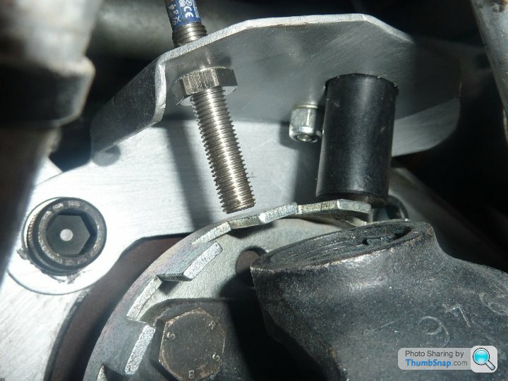
It's the Caerbont EMP-34-1 sensor on the left and I've reduce the teeth on the wheel down to 4. 16 teeth use to throw the ECU into error and 8 teeth use to hit the ECU road speed limiter. 3.5 teeth would be spot on but without RoverGauge I wouldn't even know it was over reading. This winter I plan to add the correct inline resister, in fact do you know what the resistance should be.???The sensor on the right is for my speed sensing electric PAS that I have finally perfected. Light for parking and manual above 30mph. I’ve always enjoyed a good challenge.
stevesprint said:
It's the Caerbont EMP-34-1 sensor on the left and I've reduce the teeth on the wheel down to 4. 16 teeth use to throw the ECU into error and 8 teeth use to hit the ECU road speed limiter. 3.5 teeth would be spot on but without RoverGauge I wouldn't even know it was over reading. This winter I plan to add the correct inline resister, in fact do you know what the resistance should be.???
I didn't know there was an inline resistor. Colin and I did a little experimenting with the road speed input a few month ago. I think we determined that pulse amplitude was not important. The two small vertical PC boards on the ECU seem to be custom made for the 14CUX. I believe they condition the 16 incoming signals for the ADC. Most are simple voltage or resistance measurements, however, the road speed probably goes through a frequency to voltage converter.blitzracing said:
Talking A to D's was it ever found out if the CO trim input was utilised on the catalyst map? Im under the impression that bit is turned off as you have lambda feedback.
That's correct. If you look at the control list for the ADC, you will see that the open loop maps (1,2 & 3) have a 0x09 which does a 10-bit convert on channel 9 (the CO trim voltage). The closed loop maps do not have this, although adjusting it will still have an effect, as you know. The measured value is stored in the location that is normally used for storing long term trim. I've mentioned to Colin that a possible future update to RoverGauge should include displaying this value for open loop maps.danbourassa said:
That's correct. If you look at the control list for the ADC, you will see that the open loop maps (1,2 & 3) have a 0x09 which does a 10-bit convert on channel 9 (the CO trim voltage). The closed loop maps do not have this, although adjusting it will still have an effect, as you know.
This is the bit that gets me. We have a preset voltage value for the CO trim in closed loop, but Ive not managed to see any effect, certainly on the mixture or short term trim values. Are we saying this voltage will be a starting point for the long trim mid point?Gassing Station | Griffith | Top of Page | What's New | My Stuff