Instructions to change fuel maps on 14CUX Griffith, Chimaera
Discussion


davep said:
Steve, what's happening to your secondaryLambdaR value in your system, does it vary? (It's a battery backed value so you can check there). This value is used as a reference in the Purge Valve error check in the code, where it is compared with purgeValveValue, which if not in compliance will cause fault 88 to be set.
DaveHow can I see the values of the secondaryLambda's???
It would be really useful if Colin could display the battery backed up data in RoverGauge.
danbourassa said:
Steve, you're paying attention. That's a great observation that also fooled me initially. What you will find in the code is this:
That location gets modified in several places as the 2nd byte of a 2-byte store.
It seems to me that both throttlePotMinCopy ($0053) and unnamedVariable ($0054) would need to be moved as a pair due to the double store. Locations $00A2 and $00A3 are both unused, so it may be possible to move them here. I mentioned earlier that variables can be freely moved with some limitations. This looks like one of those limitations.
Dan, thanks for your kind words and patience with a beginner, but you’re the one with the experience who knew to look for the long register instruction "std" which explains why $0053 & $0054 would have to be moved as a pair.std X0053
That location gets modified in several places as the 2nd byte of a 2-byte store.
It seems to me that both throttlePotMinCopy ($0053) and unnamedVariable ($0054) would need to be moved as a pair due to the double store. Locations $00A2 and $00A3 are both unused, so it may be possible to move them here. I mentioned earlier that variables can be freely moved with some limitations. This looks like one of those limitations.
I see at start up (reset.asm) throttlePotMinimum is copied to throttlePotMinCopy and then back again to throttlePotMinimum at shutdown to allow room for the ram checksum.
If ramChecksum($0053) is used as a single byte could Mark copy the prom checksum fixer to $0054 in shutdown just before ramChecksum is calculated and store at $0053 and then Mark could test for a prom change in startup before throttlePotMinimum is copied back to throttlePotMinCopy. Just a thought as I'm sure you approach would be easier and safer.
Dave or Dan
In the shutDown.asm code below does “Port P13 is condensor fan timer (high = OFF)” drive the Black/Green wire on pin 36 of the main harness that goes to the green/black relay base near the ECU?
In the shutDown.asm code below does “Port P13 is condensor fan timer (high = OFF)” drive the Black/Green wire on pin 36 of the main harness that goes to the green/black relay base near the ECU?
;-----------------------------------------
; If ECT and EFT sensors indicate very hot
; turn on the condenser fan timer
;-----------------------------------------
                ldaa        coolantTempCount    ; load ECT sensor count
                cmpa        hotCoolantThreshold ; value from XC1EF ($14 = 102 deg C)
                bcc         .shutdownRamChk     ; branch ahead if eng temp is cooler than this

                ldaa        fuelTempCount       ; engine is very hot, load EFT sensor count (fuel tmep)
                cmpa        hotFuelThreshold    ; value from XC1F0 ($34 = 70 deg C)
                bcc         .shutdownRamChk     ; branch ahead if underhood temp is cooler than this

                ldaa        port1data           ; Port P13 is condensor fan timer (high = OFF)
                anda        #$F7                ; ground condenser fan timer to run fans for ~10 minutes
                staa        port1data
Dave,
Not me, I’m just trying to help another 14CUX owner.
Do you know how the 10 minute timer works? Is the timer in the relay that plugs onto the black and green relay base? I wouldn’t have thought the ECU also stays powered up for the ten minutes as well.
It would be really cool if we could reprogram Port P13 to make pin 36 a normal thermostat output to control the engine cooling fans.
Here’s a diagram of the timer I ripped off one of your old posts.
eisdielenbiker said:
I would like to change over my Lucas injectors for 3rd generation Bosch injectors. There are possibly no direct flow rate replacements available. The orignals are 185 ccm per minute. There are Bosch injectors at 252 ccm available. As I am not intending to go far beyond stock setup of my 3.9 engine the old flow rate is okay for my engine. If the injectors have too much flow the mixture is directly affected in proportion to the excess flow, isnt'it ? (Lambda closed loop issues taken out of consideration) Is the cure for that problem just to multiply my 16-bit main fuel scaler of actually $5D58 by 185/252 resulting in a new scaler $4486 ? A residual problem could evolve if the duty cyle becomes to short. Is that possible? I dont have my last Rovergauge logs handy to look for the actual minimum cycle. Is there any restriction on the idle mixture of the engine to be expected ?
Yes you just need to lower the main table scalar and yes multiply $5D58 by 185/252 sounds logical but I bet it will come down to trial and error.Here's a quote from Joolz on page 16
spitfire4v8 said:
The fuel map multiplier in my mind changes the time allocated to each bit (normally termed microseconds per bit in other aftermarket ecus). What I have been doing is to massage the fuel multiplier to get the fuelling correct at the richest point on full throttle power runs on the dyno with FF in the load sites passed through during the run, then leaving the multiplier alone and going back and correcting all the other fuel map sites to get the mixture where I want it.
In this way you can maximise the resolution of the fuel map which becomes important when you are dealing with small numbers in the fuel map around idle and trailing throttle.
The multiplier therefore does become engine size dependant because a big engine will draw more air, will require more fuel, or in the case of the multiplier part - more microseconds of fuel squirted per bit.
Make sense to anyone?
CGCobra said:
Hi again.
Not been on for a while, busy with work and a bit too cold in the garage for 'playing' with the car.
Just bought another ECU, thought it may be easier swapping chips using separate ECUs rather then opening the 'main' one up all the time and also it seems like a good idea to have a backup unit for the future (not to mention got it for a good price). It fires the car up OK and all looks good in RG, then I opened it up and found it has a soldered in chip, not in socket like my original (maybe I just got lucky with that), was a bit peeved by this at first but as I want a lock/unlock holder anyway seems like it shouldn't be too difficult to remove the chip and solder in the locking socket rather than sitting one socket into another.
Obviously I'll probably fry the EEPROM removing it but I'm not bothered about that as I'm going to replace anyway but is there anything else I should look out for?
I also just downloaded RG9.2, I see there is now as setting to allow correction of the road speed, with a multiplier and an offset, this was something I "Wish-listed" a little while back, great to see that there, thanks very much gents. Not been through the new release yet (I was on 8.8 before) I guess there will be other new features, can't wait to get it hooked up to the ECU but looking at getting the body off and doing a bit of work on the oily bits over the next few weeks so may be a little while.
Thanks again guys
CGCobraNot been on for a while, busy with work and a bit too cold in the garage for 'playing' with the car.
Just bought another ECU, thought it may be easier swapping chips using separate ECUs rather then opening the 'main' one up all the time and also it seems like a good idea to have a backup unit for the future (not to mention got it for a good price). It fires the car up OK and all looks good in RG, then I opened it up and found it has a soldered in chip, not in socket like my original (maybe I just got lucky with that), was a bit peeved by this at first but as I want a lock/unlock holder anyway seems like it shouldn't be too difficult to remove the chip and solder in the locking socket rather than sitting one socket into another.
Obviously I'll probably fry the EEPROM removing it but I'm not bothered about that as I'm going to replace anyway but is there anything else I should look out for?
I also just downloaded RG9.2, I see there is now as setting to allow correction of the road speed, with a multiplier and an offset, this was something I "Wish-listed" a little while back, great to see that there, thanks very much gents. Not been through the new release yet (I was on 8.8 before) I guess there will be other new features, can't wait to get it hooked up to the ECU but looking at getting the body off and doing a bit of work on the oily bits over the next few weeks so may be a little while.
Thanks again guys
I'm pleased to hear you are back and still playing with the 14CUX. I'm sure if you offer Mark Blitzracing some beer money he'll de-solder the eprom and fit a socket for you.
Sorry, I’m to blame for the poor communications regarding the latest RoverGauge version. At the begin of Jan Colin asked me to test the new speedo re-calibration settings but due to the cold weather I’ve only managed to fire up the new version in the garage, therefore please everyone use with caution as it has not been road tested.
Colin
Please can I take this opportunity to thank you for the new RoverGauge features including the option to display the battery backup data that Dave and I are interested in.
Steve
Frol
Welcome and thanks for your interesting questions, your English is great.
Your 3604 prom is new to me and I would appreciate a copy for my collection, is your Discovery 1 originally Russian and what tune do you run?
0x1C7 is the AFM / Row centre offset and there is only one per prom unlike the AFM / Row scalar with 1 per fuel map.
You should be able to leave the row offset at 1E and simply change the AFM / Row scalar so the active row hovers between the last two rows on full load, Increasing the row scalar expands the active row down the table and decreasing it holds it higher up the table.
Row scalar extends and shrinks the usable range of the table and the offset moves the centre point of the usable range up and down and could be used to keep idle on row 2.
To increase the frequency & rpm range of RoverGauge’s active row/column turn off all unnecessary RoverGauge sensors in Options –> Edit Settings, for an even more accurate row/column reading turn on logging and check the highest value of currentFuelMapRow, I personally aim for 6.9 instead of 7 because that maximises the table and you also know it doesn’t overshot.
Sorry I don’t know what the 3 x 8 MAF table at C196 is used for but I’m pleased you’ve asked as it will be fun to investigate and could be useful.
For starting at –32C is might be worth trying Land Rover’s final (Operation Pride) R3652 cold weather prom.
The COTrim is only effective in maps 1,2 & 3 up 3,400rpm. Its basically manual control of the Lambda long term trim and its effect gradually decays towards 3,400rpm.
Good Luck
Steve
Sorry about my website, it was attacked but now restored and safe, please use this link.
http://www.stevesprint.com/remap-14cux/bins
Thanks for offering to email me your 3604 tune, I’m very interested as it could contain the final code but without the cold weather data like R3652.
As your PistonHeads profile doesn’t accept private messages please send me a private message via Pistonsheads and I’ll reply with my email address, I don’t publish my email address to stop spam/junk email, sorry.
I’m impressed with all the work you’ve done on your Discovery.
Thanks and good luck.
jjohnson23 said:
Hello all,its been a while since i`ve been on here so its good to see there is plenty activity.
One of the things I have noticed on other sites is the statement that the 14cux is not able to deal with spercharged engines.I can only assume that this is because the ecu will not cope with the non linear airflow (a 3.9 engine may be drawing a 5.0l engines airflow under boost)into the engine and of course does not use a map sensor.
Is this true or is it a case that it can be done but is difficult to do?
By the way,keep up the good work Colin,Dan,Steve et al.
Welcome back and thanks.One of the things I have noticed on other sites is the statement that the 14cux is not able to deal with spercharged engines.I can only assume that this is because the ecu will not cope with the non linear airflow (a 3.9 engine may be drawing a 5.0l engines airflow under boost)into the engine and of course does not use a map sensor.
Is this true or is it a case that it can be done but is difficult to do?
By the way,keep up the good work Colin,Dan,Steve et al.
The Italian market had a de-stroked supercharged 2000cc Rover V8 in the TVR S that produced 223bhp. It was featured in a magazine back in summer 1991 so there is a good chance it ran with a 14CUX and would be a very interesting bin/tune file to see.
Stroke: 40.25mm
bore: 88.9mm
C/R: 8.1
Supercharger:1.8 bar
http://www.pistonheads.com/gassing/topic.asp?h=0&a...
http://www.mg-cars.net/mgb-gt-v8-technical-bbs/200...
There was also a short run of non-factory Sprintex supercharged 350SX & 400SX Wedges made by the Northern TVR Centre in the mid-1980s that were definitely fuel injected but must have been the earlier flapper 4CU system.
https://en.wikipedia.org/wiki/TVR_350i
The MAF table Frol is enquiring about looks like it might control the airflow linearization and is an area Dan is considering improving with an additional look up table.
Also the airflow linearization of the Bosch airflow meter that Mark Adams uses is difference to the standard 5AM and I assume he adjusts the main fuel table cells to compensate. I would have thought your biggest issue is not having mappable ignition timing but at least there are a few options.
Cheers, Steve
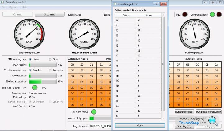
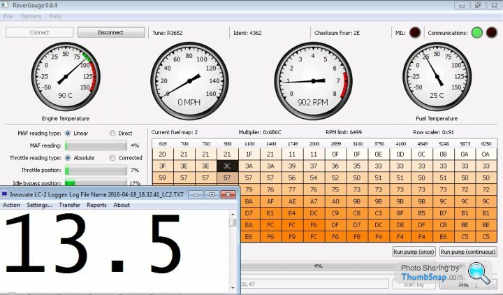
Finally the weather was good enough to get the Griff taxi out today and give RoverGauge’s new features a test drive.
You can see Colin has added two new settings, Road Speed Multiplier and offset which allow you to recalibrate RoveGauge’s Speedometer if required. The two settings worked as expected, so for example a multiplier of 2 doubles RoverGauge’s speedometer reading and the offset is added, or subtracted if negative. When the road speed is recalibrated there is a warning message below the speedo which you can see in the second screen shot. Please note RoverGauges's speedometer doesn't work on Griff 500s or Chimaeras as they are fitted with TVR fixed road speed signal generator.

Here's the new window showing the battery saved parameters that the ECU learns and saves even when the ignition is turned off.
A few of the main settings
Colin,
Thanks again for the new features, plus I see you've also improved the logs & static data as required. RoverGauge keeps getting better & better, you're a star !!!
You can see Colin has added two new settings, Road Speed Multiplier and offset which allow you to recalibrate RoveGauge’s Speedometer if required. The two settings worked as expected, so for example a multiplier of 2 doubles RoverGauge’s speedometer reading and the offset is added, or subtracted if negative. When the road speed is recalibrated there is a warning message below the speedo which you can see in the second screen shot. Please note RoverGauges's speedometer doesn't work on Griff 500s or Chimaeras as they are fitted with TVR fixed road speed signal generator.
Here's the new window showing the battery saved parameters that the ECU learns and saves even when the ignition is turned off.
A few of the main settings
| Lambda Trims | 42 & 46 |
| High Fuel Temp | 48 |
| Fault Codes | 49 –> E4 |
| Stepper Motor Value | 4F |
| Throttle POT Min Position | 51 |
Colin,
Thanks again for the new features, plus I see you've also improved the logs & static data as required. RoverGauge keeps getting better & better, you're a star !!!
Edited by stevesprint on Sunday 19th February 21:44
spitfire4v8 said:
How are people getting on with the later versions of RG ? I can't get anything later than 084 to work .. apparently this coincides with a fundamental change in the way Colin updated it and not working with certain versions of windows?
It's not a problem as the earlier versions do everything I need and more just wondered how people are getting the later versions to work?
JoolzIt's not a problem as the earlier versions do everything I need and more
just wondered how people are getting the later versions to work?I’ll bet you a beer its because you’re not also unzipping the sub-directory “platforms” that contains qwindows.dll which changed after version 8.4.
RoverGauge does not have an installation program so you can simply download and unzip http://www.remap-14cux.info/rovergauge-0.9.2-Windo... including the sub directories into a new folder anywhere on your computer. You do not have to delete your current working version, just use a new location and then create a link to the new version.
=== EDIT ====
Joolz
I've just seen your reply, looks like a windows file permission issue with platforms, I would try installing into a new location and then eventually try deleting the old. Are you logged on with administrator rights? Also, try immediately after a reboot.
Edited by stevesprint on Monday 20th February 20:58
spitfire4v8 said:
jjohnson23 said:
Regarding the TEMPERATURE FUEL MULTIPLIER TABLE.
I take it the top row is degrees F.
What do the two rows below show exactly?
Only asking as I find the engine will not tick over from a cold start but once its been running about a minute its fine.I can only think its a tad too lean when its stone cold as its fine when warmed up.
Thanks in advance,PJ.
make sure all your basic mechanical settings are good to start with, it should hold a high rpm on cold start anyway so a poor tickover is possibly something more mechanical than ecu trim related. It could also be too rich rather than too weak of course ..I take it the top row is degrees F.
What do the two rows below show exactly?
Only asking as I find the engine will not tick over from a cold start but once its been running about a minute its fine.I can only think its a tad too lean when its stone cold as its fine when warmed up.
Thanks in advance,PJ.
certainly on the tvrs the startup is very rich, 10afr from initial first start then weakening off.
ive found though that the load sites around idle (ie 700-1500rpm but load sites further down the fuel table because the stepper is open) are mapped too rich anyway, so you're running on an artificially rich part of the map, plus the richness of the warmup overfulling effect. Many tvrs exhibit a throttle-opening stalling effect from cold start which many think is a weak mix but is in fact the engine bogging down on too much fuel. You can see all this if you fit a wideband in the exhaust and look at what is actually happening to the mixture during the warm up period before the lambdas start cycling.
Make sure you've mapped the load sites around idle and 700-1500rpm / larger throttle openings properly before you get involved with modifying the warmup table, i've been pleasantly surprised how much the startup and warm up improves when you've got the basic fuel table correct, suggesting rthe startup and warmup tables arent that far out in reality.. at least on the sample of cars i've seen so far.
Very very useful idea, thanks for sharing that with us all. Hope you’ve sorted your RoverGauge, if not PM me.
Paul,
Sorry I have no experience of tweaking the warming up fuel multiplier table at PROM offsets 45B(map2) & 791(map5), however they appear to operate in the same fashion as the idle (stepper motor) temperature base table at prom offset 17B that I have worked on.
You can work out the temperatures in the top row of the temperature multiplier table from this table below and the middle row is the fuel multiplier and the bottom row is the angle of slope used to calculate the multiplier between the columns.
//   0   1   2   3   4   5   6   7   8   9   A   B   C   D   E   F
    130,129,127,126,124,123,121,120,118,117,115,114,112,111,109,108,   //  0
    106,105,104,103,102,101,100, 99, 98, 97, 96, 95, 94, 93, 92, 91,   //  1
     90, 89, 88, 87, 86, 85, 84, 83, 82, 81, 80, 79, 78, 77, 76, 75,   //  2
     74, 73, 72, 71, 70, 70, 69, 68, 67, 66, 65, 64, 63, 63, 62, 61,   //  3
     60, 59, 59, 58, 58, 57, 56, 56, 55, 55, 54, 54, 53, 52, 52, 51,   //  4
     51, 50, 50, 49, 49, 48, 48, 47, 47, 46, 46, 45, 45, 44, 44, 43,   //  5
     43, 42, 42, 41, 41, 40, 40, 39, 39, 38, 38, 37, 37, 36, 36, 35,   //  6
     35, 35, 34, 34, 33, 33, 32, 32, 31, 31, 30, 30, 29, 29, 28, 28,   //  7
     28, 28, 27, 27, 26, 26, 26, 25, 25, 24, 24, 23, 23, 23, 22, 22,   //  8
     22, 21, 21, 20, 20, 19, 19, 18, 18, 17, 17, 16, 16, 15, 15, 14,   //  9
     14, 14, 13, 13, 12, 12, 11, 11, 10, 10,  9,  9,  8,  8,  7,  7,   //  A
      7,  7,  6,  6,  6,  5,  5,  5,  4,  4,  3,  3,  3,  2,  2,  2,   //  B
      2,  1,  1,  0,  0, -1, -1, -2, -2, -3, -3, -4, -4, -5, -5, -6,   //  C
     -6, -6, -7, -7, -8, -8, -8, -9, -9,-10,-10,-11,-11,-11,-12,-12,   //  D
    -12,-13,-13,-14,-14,-15,-15,-16,-16,-17,-17,-18,-18,-19,-19,-20,   //  E
    -20,-20,-21,-21,-22,-22,-22,-23,-23,-23,-24,-24,-24,-25,-25,-25;  //  F
//   0   1   2   3   4   5   6   7   8   9   A   B   C   D   E   F

Here's the temperatures in the first row in degs C.
;                       130  81  51  21   9   1 -12 -19   Coolant Temp in Deg C
LC45B       DB          $00,$29,$50,$91,$AB,$C2,$E0,$EE ; (C791) used by CT routine (8 values)
LC463       DB          $24,$26,$29,$2D,$32,$36,$3F,$48 ; offset =  8
LC46B       DB          $03,$04,$03,$0C,$0B,$13,$29,$13 ; offset = 16
Here’s Dan's instructions to use the above temperature conversion table.
“First down then across.
Yes, 0x27 would be 2 down and 7 across. The coolant table is arranged 16 x 16 so it matches up
nicely with hex values. This is just a calibration table that we refer to often in order to
understand the 14CUX software better. It's not in the 14CUX code at all”
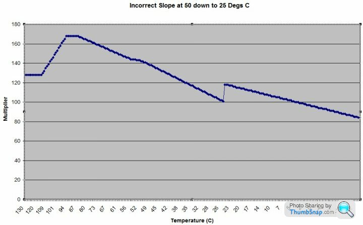
I’ve produced the following graph from the idle (stepper motor) temperature base table at prom offset 17B with the simulation program I wrote and inserted an incorrect slope (last row) at 50 Degs C to demonstrate the importance of correcting the slope.
Hopefully one day I'll get a chance to write a similar simulator for the temperature based fuel multiplier table but for now I suggest you try Joolz approach first.
Edited by stevesprint on Sunday 5th March 23:30
Paul
I've just had a very quick look though some tune files and discovered the following three different warming up fuel multiplier tables and thought you might like to try the Land Rover 4.2 UK R3116 table as it has the lowest multipliers below 50 degs C and the same value as yours at 80 degs C.
You’ve also got me thinking about the 3 by 12 cranking fuel table above in each map that has a timer in the third row which slowly decays the extra fueling (in row 2) after cranking.
Dave and Dan
Am I right thinking a timer value of $1E = 30 in decimal and therefore the extra cranking fuel takes 30 seconds to completely decay??? Well, I assume it decays slowly as I don't actually know.
The fuel temp sensor output is used all the time unlike the thermo timer switch on the older 4CU flapper system which is only used for a few seconds from cold.
I’m pleased you’ve brought the coolant temperature based fuel adjustment table to my attention as I’ve now wired my AFR gauge to a separate battery so I can monitor the AFR immediately after cranking and discovered there is room for improvement. Cranking at 12 degs C the AFR was 13 for the first 4 secs and then drops to 11.5 and slowly increased to 12.3 AFR after 25 seconds and keeps slowly rising during warm up.
As the standard 4.2 table has different temperature set points in the top row I've modified the 3.9 table to reduce the fuelling only below normal running temperature and knocked up a simulator program to create this graph. My Griff starts and warms up smoothly with this table and therefore should be safe to try.
13081 51 21 09 01-12-19 ; 3.9 Coolant Temperature in Deg C
00 29 50 91 AB C2 E0 EE ; 3.9 Coolant Temperature set points
26 26 28 2A 30 36 3F 48 ; Leaner warm up multipliers
00 04 02 0F 10 13 29 13 ; corrected slope
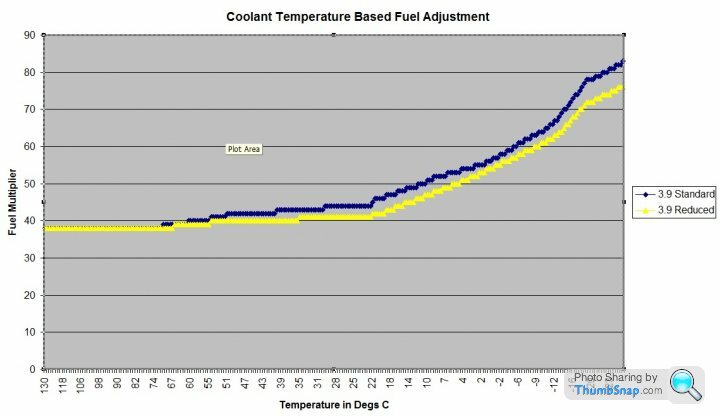
The coolant temperature based fuel adjustment table is already in TunerPro. Its called "MAP 2 TEMPERATURE FUEL MULTIPLIER - Green", you may not have recognized as it only contains the last two rows plus its data values were all decimal & not hex which I've now changed back to hex.
http://www.remap-14cux.info/TunerPro-xdf.zip
I've just had a very quick look though some tune files and discovered the following three different warming up fuel multiplier tables and thought you might like to try the Land Rover 4.2 UK R3116 table as it has the lowest multipliers below 50 degs C and the same value as yours at 80 degs C.
Coolant termerature base fuel adjustment table
Land Rover all 3.9s (R2925,3383,3652) and TVR 400 CAT & Precat, Griff 500 1994 & 95, 450CAT, 430BV CAT, MGR R2967 & R3452
;                       130  81  51  21   9   1 -12 -19   Coolant Temp in Deg C
LC45B       DB          $00,$29,$50,$91,$AB,$C2,$E0,$EE
LC463       DB          $26,$26,$2A,$2E,$34,$38,$43,$4E
LC46B       DB          $00,$06,$03,$0E,$0B,$17,$32,$14

430BV (Mine)
LC45B       DB          $00,$29,$50,$91,$AB,$C2,$E0,$EE ; (C791) used by CT routine (8 values)
LC463       DB          $24,$26,$29,$2D,$32,$36,$3F,$48 ; offset =  8
LC46B       DB          $03,$04,$03,$0C,$0B,$13,$29,$13 ; offset = 16

Land Rover 4.2 UK (R3116)
LC45B       DB          $00,$24,$38,$67,$AB,$C2,$E0,$EE
LC463       DB          $26,$26,$29,$2A,$32,$38,$43,$4E
LC46B       DB          $00,$09,$01,$08,$11,$17,$32,$14


Cranking fuel table with timer
                    130 102  95  85  56  33  17   7  -2 -10 -14 -16  Coolant Temp in Deg C

LC76D   DB  $00,$12,$1B,$25,$47,$75,$99,$B0,$C8,$DA,$E4,$E8 ; coolant temp sensor reading (low is hot, high is cold)
LC779   DB  $0B,$0A,$07,$0D,$1A,$1C,$31,$46,$4E,$59,$6D,$75 ; cranking fueling value above zero deg F (stored in X009B)
LC785   DB  $1C,$0D,$06,$0A,$10,$12,$1E,$26,$2C,$31,$39,$44 ; time fueling component, 1 Hz countdown (stored in X009C)
You’ve also got me thinking about the 3 by 12 cranking fuel table above in each map that has a timer in the third row which slowly decays the extra fueling (in row 2) after cranking.
Dave and Dan
Am I right thinking a timer value of $1E = 30 in decimal and therefore the extra cranking fuel takes 30 seconds to completely decay??? Well, I assume it decays slowly as I don't actually know.
==== Edit ====
jjohnson23 said:
does the fuel temp sensor output only function during start up or does it have a function all the time the engine is running?Only asking as my XDF for TunerPro does not have a table for this.
PaulThe fuel temp sensor output is used all the time unlike the thermo timer switch on the older 4CU flapper system which is only used for a few seconds from cold.
I’m pleased you’ve brought the coolant temperature based fuel adjustment table to my attention as I’ve now wired my AFR gauge to a separate battery so I can monitor the AFR immediately after cranking and discovered there is room for improvement. Cranking at 12 degs C the AFR was 13 for the first 4 secs and then drops to 11.5 and slowly increased to 12.3 AFR after 25 seconds and keeps slowly rising during warm up.
As the standard 4.2 table has different temperature set points in the top row I've modified the 3.9 table to reduce the fuelling only below normal running temperature and knocked up a simulator program to create this graph. My Griff starts and warms up smoothly with this table and therefore should be safe to try.
13081 51 21 09 01-12-19 ; 3.9 Coolant Temperature in Deg C
00 29 50 91 AB C2 E0 EE ; 3.9 Coolant Temperature set points
26 26 28 2A 30 36 3F 48 ; Leaner warm up multipliers
00 04 02 0F 10 13 29 13 ; corrected slope
The coolant temperature based fuel adjustment table is already in TunerPro. Its called "MAP 2 TEMPERATURE FUEL MULTIPLIER - Green", you may not have recognized as it only contains the last two rows plus its data values were all decimal & not hex which I've now changed back to hex.
http://www.remap-14cux.info/TunerPro-xdf.zip
Edited by stevesprint on Sunday 12th March 21:17
jjohnson23 said:
Thank you for the information regarding the coolant and fuel warm up tables Steve.
I have had a good look at the whole fuel injection system over the weekend and have noticed that the fuel pump is a little noisy.While running the pump via Rovergauge I noticed that the pump would occasionally stop and then restart(the stop was no more than a pulse).I thought this would be a fault with the pump but after connecting a voltmeter the signal from the ecu is being disrupted-no issues when pump connected direct to battery.Is this a function of Rovergauge(9.2 and 8.4 tried)?I will try a different laptop and see what happens.
No, that's not a function of RoverGauge, the pump should run constantly when triggered via RoverGauge. Try checking the fuel pump output at the ECU and also at the fuel pump relay.I have had a good look at the whole fuel injection system over the weekend and have noticed that the fuel pump is a little noisy.While running the pump via Rovergauge I noticed that the pump would occasionally stop and then restart(the stop was no more than a pulse).I thought this would be a fault with the pump but after connecting a voltmeter the signal from the ecu is being disrupted-no issues when pump connected direct to battery.Is this a function of Rovergauge(9.2 and 8.4 tried)?I will try a different laptop and see what happens.
cosecon said:
Hi everybody, I am amazed by the information available concerning 14cux.
I would also like to thank creators of rovergauge which is an amazing tool and Steve for getting into the trouble of collecting all the info together.
In Steve's page there are plenty of original and modified tune-files everybody can use.
I was wondering is there are any files modified for air flow meter 20AM. It sounds to me very complicated to modify my self.
Thanks for your kind words.I would also like to thank creators of rovergauge which is an amazing tool and Steve for getting into the trouble of collecting all the info together.
In Steve's page there are plenty of original and modified tune-files everybody can use.
I was wondering is there are any files modified for air flow meter 20AM. It sounds to me very complicated to modify my self.
Here's the 20AM wiring diagram courtesy of Mark Blitzracing
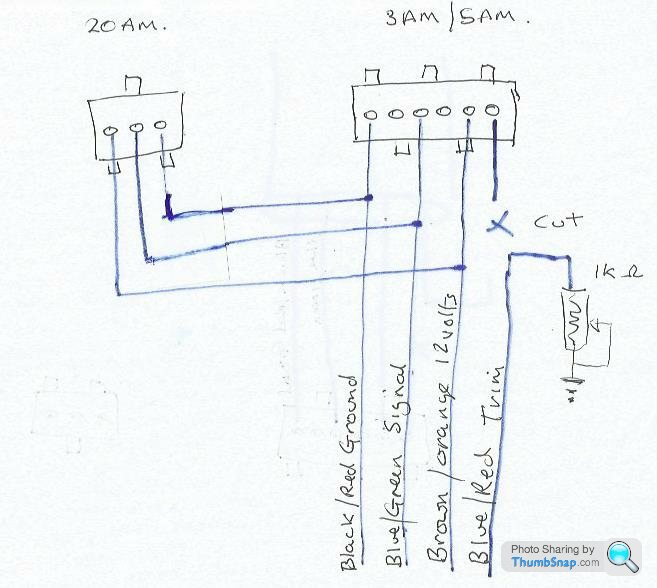
You’ll need an EPROM programmer and a copy of TunerPro to change the Row Scalar in the ECU and then a full remap, alternatively visit http://www.kitsandclassics.co.uk/ or Mark Adams.
briantvr350i said:
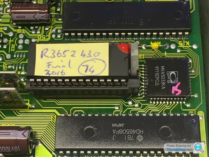
My question is very simple, apart from the obvious different software programmed into the different variations is there any real difference in the 14CUX hardware?
My current understanding is that the "TVR" variations had a socket installed instead of a soldered in ROM (EEPROM, OTP ROM or whatever)
Would it be possible to obtain any 14CUX ecu, remove (very carefully) the existing ROM and replace with a socket. Then it should be possible to program EEPROM's with the latest variation in code
Correct, All 1991 and onwards ECUs have identical hardware, they can be identified by the MVA5033KA chip at the end of the EPROM.My current understanding is that the "TVR" variations had a socket installed instead of a soldered in ROM (EEPROM, OTP ROM or whatever)
Would it be possible to obtain any 14CUX ecu, remove (very carefully) the existing ROM and replace with a socket. Then it should be possible to program EEPROM's with the latest variation in code
1991 onwards (from tune R2422 onwards)
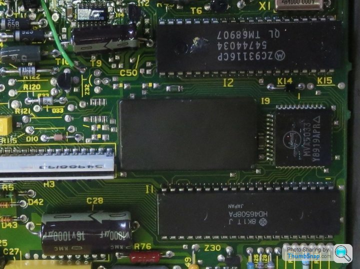
Here's a Pre 1991 one to avoid (note the MVA5033 chip number is missing KA at the end)
========= Edit 30/04/2017 ============
blitzracing said:
Basically nothing more than the socket and remap, but there are two versions of 14CUX, and the early versions dont work correctly with the later fuel maps. Its around 1990 that change took place.
A few years ago I was informed the very early 14CUXs actually run maps 1,2 & 3 ok but not maps 4 & 5, so must be due to lambda control updates.Edited by stevesprint on Sunday 30th April 17:10
Mjstemp1 said:
Back playing with my 4.6L after a long cold winter. Now that I have my programmer I have burned Steve's R3652_430 basic chip and running it on Map 5 as I dont need the higher RPM versions. All is fine down the road but my cam does not like the Closed Loop setup at idle. Plus neither does my nose! Switching to Map 2 gives a much better idle and I have no Cats so not an issue. Have not tried it driving for fear it may be too lean on the 4.3L mapping.
Sorry for the delayed response, I keep being distracted by my sons projects that are taking over the garage.Please let me know if you have any idle issues with R3652_430 particularly while coasting or slowing as I’ve made some improvements that I only updated R3652_430_6250 for a request, here's a copy www.remap-14cux.info/bins/R3652_430_6250.bin . I’ll apply the same idle improvements to R3652_430_5500, test and upload.
Mjstemp1 said:
So my question is do I just copy the Map 5 table into Map 2 along with the Main Scalar and Row Scalar and burn a new chip and hence run Open Loop in my new Map 2, plus set the CO at 1.4V. Or can the "Enable Long Term Trim" in TunerPro be deactivated and I stay in Map 5? Reading back through all these pages I get the impression that I will eventually throw codes by going that way.
Guess I will try it out and see what I get for AFR. When copying Map 5 to Map 2 it's just two multipliers and the full fuel table right? Anything else to change in Map 2 to get started?
All 5 maps contain the following 4 tables so you really need to copy all 4 tables plus the main scalar and the last 8 bytes from map 5 to 2.Guess I will try it out and see what I get for AFR. When copying Map 5 to Map 2 it's just two multipliers and the full fuel table right? Anything else to change in Map 2 to get started?
1. Main fuel table and & scalar
2. Throttle adjustment table
3. Cranking fuel table
4. Warn up fuel adjustment table
5. Last 8 bytes (RPM Limiter, AFM Scalar, warm up threshold, full load additive & Deceleration gain.
Do not copy the 32 bytes between the the warm up fuel adjustment table and last 8 bytes.
“Enable Long Term Trim” definitely disables the long trim and you’re right will eventually throw a fault code that can actually be ignored, but I'm not sure if it also disables the short term trim.
I'll copy map 5 to 2 for you.
Mjstemp1 said:
Or is there a way to adjust the Closed Loop AFR to say 13 for idle in my existing Map 5?
This is something Mark and Dan experimented with last year and eisdielenbiker has recently changed the program code to force open loop on row 3 onwards so you never know, maybe one day.Mjstemp1 said:
Forgot to mention I have a wideband sensor already installed.
If you can’t datalog you could try filming your AEM gauge and RoverGauge at the same time with a mobile or GoPro, I heard its been done successfully before.Mjstemp1 said:
My car is MGB with single exhaust so even with Steve's chip with extended rpm and increased sound track, I get little audio enlightenment! So I went back to his R3652 430 and 450 Cat chip.
If you’re running closed loop 5 you’ll struggle to get overrun pops as the ECU will try to correct the AFR back to 14.7, however if map 2 (open loop) set your overrun AFR around 18 AFR above 1750 rpm.Mjstemp1 said:
What I am not following in you post is why I would be so far off if I copy Map5 to Map 2.
As you know Map 5 is set for 14.7 to save the planet and your CATs but isn’t the best for economy,power or smoothness, open loop map 2 allows the AFR to be set as required, for example
12.5 to 13 best full load power and acceleration
13.5 smooth in slow moving traffic.
14.7 less pollutants
15.5 to 16 best light cruise economy
Mjstemp1 said:
Map 5 is for a TVR 450 which is more or less my 4.6L is it not?
I assumed the full Lamda control would just be fine tuning below 3400 rpm, full throttle would be the same for any 450 or 4.6?
R3652_430 Map 5 is straight from a TVR 450 Chimmy which actually have late 4.6s but with 4.0 pistons to increase the compression ratio, therefore ideal for your 4.6L if you run map 5 closed loop. However, believe it or not the open loop 430 map 2 is much richer that the 450 closed loop map 5. Both have the same Air Flow Meter scalar but the 430BV main fuel table scalar 6B6C is higher than the 450 map 5 main fuel table scalar 6978, interestingly the Griff 500 main fuel scalar is 6784.I assumed the full Lamda control would just be fine tuning below 3400 rpm, full throttle would be the same for any 450 or 4.6?
Do not under estimate the 430 map 2 as its also for pre-CAT 430 Big Valves and is the richest 14CUX map, its even richer than the Griff 500 map 5, Pre-CAT 430BV actually have more BHP & torque than Chimmy 450s (4.6L with CATs) so it’s certainly worth a test drive.
============= Edit ===============
Mjstemp1, here you go, I'll test them today, weather permitting
www.remap-14cux.info/bins/R3652_430_5500.bin (Map2 4.3BV & Map5 450)
www.remap-14cux.info/bins/R3652_4.6_5500.bin (Map2 450 & Map5 450)
Edited by stevesprint on Monday 1st May 19:01
Mjstemp1 said:
Steve,
Wow, thanks very much for all your efforts!
As to "idle issues with R3652_430 particularly while coasting or slowing" on your R3652_430 Bin, I did have some during warm up in particular. Found this on both Map2 and Map5. Once fully warm they were less of an issue. I now have a working Road Speed sensor, although its reading 1.8 times what it should be. T5 with VDO Hall Sensor needed a small conversion box to allow ECU to get the 0-12V square signal. Also has about a 2-3 second delay once fully stopped before idle drops to 950. Tried looking at the address in the bin file for it but could not tell which way to modify the "Road Speed Comparator for different sensors". As long as I have 0 KPH when stopped and no longer have a speed limiter, dont see if its really any issue?
Pleasure, The idle updates in the two latest bins should help as they have a lower coasting idle. Increasing PROM offset 242 lowers the coasting idle hot and cold plus the initial cranking idle can be adjusted independently if required.Wow, thanks very much for all your efforts!
As to "idle issues with R3652_430 particularly while coasting or slowing" on your R3652_430 Bin, I did have some during warm up in particular. Found this on both Map2 and Map5. Once fully warm they were less of an issue. I now have a working Road Speed sensor, although its reading 1.8 times what it should be. T5 with VDO Hall Sensor needed a small conversion box to allow ECU to get the 0-12V square signal. Also has about a 2-3 second delay once fully stopped before idle drops to 950. Tried looking at the address in the bin file for it but could not tell which way to modify the "Road Speed Comparator for different sensors". As long as I have 0 KPH when stopped and no longer have a speed limiter, dont see if its really any issue?
The 2-3 seconds delay dropping to 950rpm is typical and hopefully will be less obvious with the lower coasting idle in the latest bins. I personally don’t mind a slightly raised coasting idle as it helps smoothness in slow moving traffic. At least you know your road speed sensor works and is best left alone if its not causing any issues, the road speed limiter is removed in all my bins. You can change RoverGauge’s speedo calibration in the latest version but unfortunately the latest version of RoverGauge doesn’t show the table column headings, I have informed Colin.
“Road Speed Comparator for different sensors” changes the voltage input sensitive of the speedo input for lower voltage signals but sadly doesn’t change the internal ECU speedo calibration. DaveP has recalibrated his ECU internal speedo by modifying the 14CUX program code, alternative would it be possible for you to half the number of teeth on your crown wheel and recalibrate your speedo?
Mjstemp1 said:
Tried out the Map2 R3652_430 from your original files last night. Looked a bit lean under mid throttle, mid 16s. Once full throttle and above 3400 rpm, back into the mid 12 though. Need to recheck the CO, was set at 1.4V before and have not touched the air flow meter but have not verified it recently. Will try out your R3652_430_5000 bin on Map2 latter this week.
Today I gave both R3652_430_5500.bin (containing OEM precat 4.3 fuel table) map 2 & R3652_4.6_5500.bin Map2 a very quick test drive to check they run ok, both drove very well and didn’t appear to have a massive AFR difference judging from the dash AFR gauge.R3652_4.6_5500

R3652_430_5500 (with TVR OEM Fuel Table)

My modified and extended fuel table I normally run.
AFR table with my modified and extended fuel table.

Mjstemp1 said:
Steve,
On a side note, any one considering the analog AEM AFR meter, there is no data logging ability. Their other gauges can do this but not the nice looking analog version. Other than that issue it is a good meter though. Now if only i had placed it where I could easily video it and the RG!
Steve, thank you again for all your help.
I’m sure Mark Blitz could recommend a digital USB data logger to connect to the White & Brown wires and maybe then I could help merge your AFR log with RoverGauge logs.On a side note, any one considering the analog AEM AFR meter, there is no data logging ability. Their other gauges can do this but not the nice looking analog version. Other than that issue it is a good meter though. Now if only i had placed it where I could easily video it and the RG!
Steve, thank you again for all your help.

Edited by stevesprint on Tuesday 2nd May 08:34
Mjstemp1 said:
Steve,
Was able to trial the R3652 430 5500. Works rather well. Will try to video log, ha ha, this weekend but from looking at the AFR gauge feel this meets my requirements.
My road speed sensor is coming off of the T5 transmission, this is from an internal gear etc, not at all like your set up. Now that I am using this also to run the ECU it giving some issues. The speedo is now rather slow to go to 0 when stopping and I feel it's causing the higher idle to linger too long. May have to look for another sensor to feed the ECU. Was planing on adding cruise control and this could give me a better input for the ECU.
Thanks for you help,
Mike
Roughly how high is the idle when it lingers as you can lower it in the data by increasing prom offset 242, is it more of an issue when cold, warming up or hot ?Was able to trial the R3652 430 5500. Works rather well. Will try to video log, ha ha, this weekend but from looking at the AFR gauge feel this meets my requirements.
My road speed sensor is coming off of the T5 transmission, this is from an internal gear etc, not at all like your set up. Now that I am using this also to run the ECU it giving some issues. The speedo is now rather slow to go to 0 when stopping and I feel it's causing the higher idle to linger too long. May have to look for another sensor to feed the ECU. Was planing on adding cruise control and this could give me a better input for the ECU.
Thanks for you help,
Mike
Mjstemp1 said:
Steve,
The one causing my issues is the warm coasting idle. Its over 1300 rpm and with my slow acting speedo takes too long at a stop to drop down for my liking. I see offset 242 is now at 8C, original "Operation Pride" looks to have been 6C. Keeping the increment the same (base 10 = +32), would AC be a good first step?
Thanks,
Mike
Try smaller steps, maybe hex 94 as you run the risk of lowering the hot lingering idle too much, but on the other hand may suit you. Its all bit of a compromise with the old 14CUX and our limited knowledge, also don't forget you need a slightly raised idle during warming up.The one causing my issues is the warm coasting idle. Its over 1300 rpm and with my slow acting speedo takes too long at a stop to drop down for my liking. I see offset 242 is now at 8C, original "Operation Pride" looks to have been 6C. Keeping the increment the same (base 10 = +32), would AC be a good first step?
Thanks,
Mike
==== Edit ====
Prom offset 242 is used to initialise the stepper motor value that is stored and saved by the battery and therefore a complete power off ECU reset is required to reload offset 242.Edited by stevesprint on Thursday 11th May 23:26
Gassing Station | Griffith | Top of Page | What's New | My Stuff