Instructions to change fuel maps on 14CUX Griffith, Chimaera
Discussion


stevesprint said:
blitzracing said:
Talking of Mark Adams- I notice his Tornado maps run up to 6000 rpm, whilst the TVR ones peak out at the original 5500 rpm.
You may remember Dan has given us an extended rpm table that goes up to 6,200 that he smoothed between the rev points. I’ll help you install it one day over a beer.Cheers
Steve
spitfire4v8 said:
I think i've missed this one .. I know there was an example of an extended rpm table but that it was somewhat less than smooth .. didn't realise a smoothed version had been done. My poor memory ..
My experience indicates that even if you already have an extended or aftermarket RPM table, you should probably have Steve check it for smooth bracket transitions. He can model it and show it graphically. At this point, he probably knows more than anyone about the subject. It would be a beer well spent.Getting back to road speed if I may... The goal of the 14CUX software is to sample the incoming VSS square wave often enough to count all the high to low transitions. This measurement is done by putting the Hitachi ADC in comparator mode. The advantage of this mode is that where the 8-bit or 10-bit conversion takes about 80 microSeconds or more, the comparator 1-bit conversion takes only 18 microSeconds. Still a long time when you consider how often this measurement is being done.
I did some investigating of the strobing problem. It seemed to me that the number of samples should be adequate. It turns out that the problem may be more related to how they are distributed.
The first oscilloscope screen shot shows the duration of the fueling interrupt on the top trace (about 5 mSec) and the second screen shot shows the non-fueling interrupt (about 3.5 mSec). The bottom trace on each shot shows the VSS samples. The long interrupt has 8 samples and the short interrupt has 6. You can clearly see that they look haphazardly placed and certainly not distributed well.
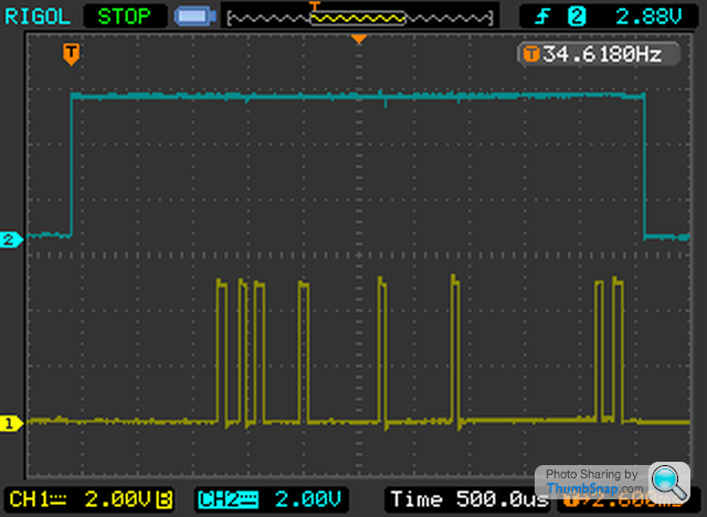
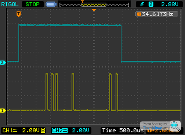
There is no need to have samples as close together as some of these are. The VSS waveform is no higher than 300 or 400Hz so a sample every 1 mSec or so should do it. Spreading these samples out a little more evenly will certainly help things but that's not the whole story.
When the interrupt terminates, the main loop goes back to executing the ADC table. The need to get another sample in during this time forced the original developers to put the road speed measurement ($87) first in the ADC list to make sure it gets called before the next interrupt takes control of the processor. There is also a special ADC list that gets used under high RPM high throttle conditions (see hiRPMAdcMux in the data file).
Of course, measuring the 4 MPH idle threshold is easy since the VSS waveform is so slow to change state. The "need" for all this extra burden on the processor at high RPM (when the processor can least afford it) is solely to limit road speed. TVR code has no road speed limit (at least not the later TVR code) but these measurements and the special ADC table are still active in the software. To make matters worse, with the special 2-state road speed box, some TVR owners don't even benefit from the actual road speed being measured and logged.
I did some investigating of the strobing problem. It seemed to me that the number of samples should be adequate. It turns out that the problem may be more related to how they are distributed.
The first oscilloscope screen shot shows the duration of the fueling interrupt on the top trace (about 5 mSec) and the second screen shot shows the non-fueling interrupt (about 3.5 mSec). The bottom trace on each shot shows the VSS samples. The long interrupt has 8 samples and the short interrupt has 6. You can clearly see that they look haphazardly placed and certainly not distributed well.
There is no need to have samples as close together as some of these are. The VSS waveform is no higher than 300 or 400Hz so a sample every 1 mSec or so should do it. Spreading these samples out a little more evenly will certainly help things but that's not the whole story.
When the interrupt terminates, the main loop goes back to executing the ADC table. The need to get another sample in during this time forced the original developers to put the road speed measurement ($87) first in the ADC list to make sure it gets called before the next interrupt takes control of the processor. There is also a special ADC list that gets used under high RPM high throttle conditions (see hiRPMAdcMux in the data file).
Of course, measuring the 4 MPH idle threshold is easy since the VSS waveform is so slow to change state. The "need" for all this extra burden on the processor at high RPM (when the processor can least afford it) is solely to limit road speed. TVR code has no road speed limit (at least not the later TVR code) but these measurements and the special ADC table are still active in the software. To make matters worse, with the special 2-state road speed box, some TVR owners don't even benefit from the actual road speed being measured and logged.
Edited by danbourassa on Wednesday 26th March 00:00
danbourassa said:
When the interrupt terminates, the main loop goes back to executing the ADC table. The need to get another sample in during this time forced the original developers to put the road speed measurement ($87) first in the ADC list to make sure it gets called before the next interrupt takes control of the processor. There is also a special ADC list that gets used under high RPM high throttle conditions (see hiRPMAdcMux in the data file).
I'd like to add to this by pointing out that the high-RPM ADC mux table likely doesn't even have the intended effect improving road speed sampling. At very high RPM, the ICI barely has time to complete and return before it's called again. When there is some time available between spark interrupts, the ADC table is started again from the first entry; so, the special high-speed table would only work as intended below a certain critical RPM at which the timeline is completely saturated by ICI operation.When I consider the above, together with the fact that the road speed is sampled within the ICI (and therefore sampled more frequently at high RPM anyway), I'm not convinced that the high-RPM mux table is helpful at all.
Dan, Colin really you two should write a book. But I would ask you not to post late in the day as the problems you pose do cause me sleepless nights.
Having read your recent posts, and when looking at the flowcharts and considering the timelines for the Main Loop and ICI code it strikes me that the 14CUX head developer/system designer, when carving up the processor time and setting priorities, leaned very heavily in favour of the ICI team. And then added insult to injury by loading the Main Loop with additional encumbrances before it even gets to do its real work: Reset Stack, MIL and fault code handling, redundant development code, a 'redundant' high RPM ADC control table and then, eventually, Main Loop makes a start. But instead of getting straight on with sensing the essential inputs it then has to look at more important matters such as Air Con On or Off and MIL lights, where's the logic in that? Finally, the ADC routines where the essential inputs are serviced can select a channel for conversion and action the relevant service routine, at last. Of course during all of this ICI can stick its oar in.
Having read Dan's thoughts on the developer rationale for putting $87 Road Speed first in the ADC table I've now realised why $02 Airflow warrants three entries, its location in the Main Loop.
It has taken some time but the overall flow and some of the detail is starting to make sense to me ... I think. Once again thanks for your efforts and sharing the results with us.
BTW is the Minus One World portal buried in the Main Loop as well?
Edited by davep on Wednesday 26th March 10:36
Thinking about this from a purely mechanical viewpoint because much of what you clever guys write goes waaay over my head.. Is the road speed given low priority because land rovers and range rovers are largely aerodynamically limited on road speed anyway? In their original 3,5 litre sub 150hp guise they would need quite a hill to trouble the limiter in the real world ..
spitfire4v8 said:
Thinking about this from a purely mechanical viewpoint because much of what you clever guys write goes waaay over my head.. Is the road speed given low priority because land rovers and range rovers are largely aerodynamically limited on road speed anyway? In their original 3,5 litre sub 150hp guise they would need quite a hill to trouble the limiter in the real world ..
I haven't studied the older ECU which was mated to the 3.5 litre. I think it was the 13CU or the 14CU. I agree. It seems that a road speed limit would never be reached on these vehicles. It's actually given a high priority on the 14CUX. If I were to guess, I would say that the NAS market was the driving force for this. It may have been OEM tire limits or just an estimated safe limit due to handling and center of gravity. We are highly litigious over here, in case you haven't noticed. The result is that TVR had to leave the US market because they couldn't afford the insurance and we are left with lawyer jokes to amuse each other.Do I sound angry?
davep said:
Dan, Colin really you two should write a book. But I would ask you not to post late in the day as the problems you pose do cause me sleepless nights.
OK Dave, I'm posting this early so you have a distracted day instead of a sleepless night. You seem to understand the code well enough now to realize that it's the result of many ad hoc patches added over time. I also hope that the few us still reading this thread won't mind if we get a little more technical about code analysis. If necessary, we can put a warning at the top of the thread: "Contents may cause death".Yes, the processor runs out of time at high RPM and the main loop gets starved out as the interrupt hogs more of the timeline. This is probably why the MAF and throttle pot are actually measured in the interrupt itself, even though they are already in the ADC rotation. These are the two most important parameters and this was probably the only way to make sure they were measured often enough.
At various points during development, there were efforts to gain efficiency and save time. Some of these are obvious. The most obvious is the calculation of the RPM value which is bypassed when RPM reaches around 1950. This one function alone amazingly takes a full 1 milliSecond to complete, which is 20 to 30% of the whole interrupt time. Interestingly, they missed a great opportunity here and could have done it in half that time (but that's another post).
A less obvious timesaver is the way the road speed (VSS) is sampled in Defender code (tune R3365). Lets take a look at a call to the road speed comparator subroutine.
IF BUILD_R3365
;-----------------------------------------------------------
; Defender Only (R3365)
;-----------------------------------------------------------

.LE57A          ldaa        #$27                ; select comparator mode and channel 7 (VSS)
                staa        AdcControlReg1
                ldaa        #$C8  ; set the high/low threshold
                staa        AdcDataLow  ; measurement now in progress
                jsr         LFA46  ; call subroutine that waits for competion and processes result
ELSE

.LE57A          jsr         rdSpdCompTest       ; call road speed comparator test (conventional subroutine)

ENDC
For those not familiar, the IF/ELSE/ENDC construct works just like that in C or other languages. This shows that all code versions except R3365 Jump to SubRoutine (jsr) Road Speed Comparator Test (rdSpdCompTest). But R3365 does some of the work before hand, then jumps to a reduced subroutine (labeled LFA46).
It wasn't initially clear to me why this was changed but I'm sure I understand it now. The conventional approach just goes to the subroutine which then triggers and waits for the measurement. The Defender code triggers the measurment first and then goes to the subroutine, thereby shortening the wait time by at least 5 microseconds (the time it takes to execute the JSR). Remember that this is done 6 or 8 times during each interrupt, so it adds up.
This is certainly an efficiency improvement to the code. Unfortunately, it's seems wasted on a Defender while the high RPM cars that need it most, don't have this improvement.
Code differences, like this one, from one tune to the next are interesting to me since they start to paint a clearer picture of Lucas' software development process. Why wasn't this change applied to R3526? Was it a separate development team? It seems to hint at the code having been a separate branch in the development tree. This seems to contradict the original software architecture where all the application specifics are in the data section and only a single version of code is needed to serve all applications. Oh well, so much for planning. Having been through the software development process many times myself, I can understand how this can happen.
davep said:
BTW is the Minus One World portal buried in the Main Loop as well?
We'll have to ask Steve about that!Edited by danbourassa on Wednesday 26th March 12:09
Edited by danbourassa on Wednesday 26th March 12:10
cmb said:
danbourassa said:
I suspect that Colin rejects the $FFFF value in RG.
The code simply shifts the stored value right by seven positions before using the result to compute the trim voltage. The lowest seven bits are therefore don't-cares because they're shifted out. After the shift, the highest possible value is 0x1FF, which is approximately half of the maximum ADC reading of 1024 counts. The result is a maximum measurement of 2.5V.It looks like the load $FFFF part stores the maximum 10 bit count value of 0x3FF if a voltage > 5 Vdc has occurred, 0x7FF (C bit of CCR is 1).
Of course I could have read the instruction manual all wrong and the above is poppycock.
Dave, you always seem to ask the right questions to get me thinking differently about something. I have completely changed my mind about this one.
The only reason they would have left shifted the CO trim this way and written it to both long term trim locations HAD TO BE direct control of the long term trim. It works too perfectly to be anything else. It must have been a mode that was used for code development and test and there was a procedure for getting into this mode, which Steve found, of course. Theoretically, it would also work if it was 6 shifts instead of 7 but you would need to turn the pot twice as much. You would also need the full 5.0 Volts to get +100% which may not be possible. It's all starting to make more sense.
This may have been a way to slightly shift the fuel mix richer or leaner during open loop map development.
spitfire4v8 said:
stevesprint said:
blitzracing said:
Talking of Mark Adams- I notice his Tornado maps run up to 6000 rpm, whilst the TVR ones peak out at the original 5500 rpm.
You may remember Dan has given us an extended rpm table that goes up to 6,200 that he smoothed between the rev points. I’ll help you install it one day over a beer.Cheers
Steve
Dave, Its really good to see you are getting your head around the code, I’m jealous. Even though I'm not familiar with assembler I can just about follow the principles. I wish I had more 14CUX time to learn assembler but my life is full on at work, home and in the garage.
Also Dan, do you think the code was written from scratch specially for the 14CUX or ported from a similar 8-bit Motorola ECU, their must be other ECU's with a processor from the same family. , I guess its something to do with me hot switching between tune resistors. So I'll reset my ECU and start testing with only tune resistor 5, then I'll try switch between 2 and 5 as I do.
blitzracing said:
Simple reason for the speed limiter- its called off road tyres- nothing more complex.
Dan, sound like you can't just strip out the road speed sensor code for Land Rover proms as it may have insurance implications.Also Dan, do you think the code was written from scratch specially for the 14CUX or ported from a similar 8-bit Motorola ECU, their must be other ECU's with a processor from the same family.
danbourassa said:
It must have been a mode that was used for code development and test and there was a procedure for getting into this mode, which Steve found, of course.
It’s always my fault , I guess its something to do with me hot switching between tune resistors. So I'll reset my ECU and start testing with only tune resistor 5, then I'll try switch between 2 and 5 as I do. stevesprint said:
Dan, sound like you can't just strip out the road speed sensor code for Land Rover proms as it may have insurance implications.
These vehicles are old now so I don't think it matters. And who would know?I hesitate to strip it out because it can be improved and I appreciate having road speed in my log files. As a compromise, I may want to bypass road speed measurements when RPM gets high.
stevesprint said:
Also Dan, do you think the code was written from scratch specially for the 14CUX or ported from a similar 8-bit Motorola ECU, their must be other ECU's with a processor from the same family.
The design was licensed from Bosch and started as the L-Jetronic design. I think the Bosch design was based to some degree on a Motorola reference design that I have been searching for. The MC6803U4 was probably introduced specifically for electronic F.I. applications. Do you remember buying a SAAB unit that was very similar?stevesprint said:
It’s always my fault , I guess its something to do with me hot switching between tune resistors. So I'll reset my ECU and start testing with only tune resistor 5, then I'll try switch between 2 and 5 as I do.
Steve, I consider this a valuable discovery., I guess its something to do with me hot switching between tune resistors. So I'll reset my ECU and start testing with only tune resistor 5, then I'll try switch between 2 and 5 as I do. stevesprint said:
Also Dan, do you think the code was written from scratch specially for the 14CUX or ported from a similar 8-bit Motorola ECU, their must be other ECU's with a processor from the same family.
As Dan said, the 14CUX likely started as a Motorola reference design, but there are indeed other FI systems designed around this processor. Perhaps the best documented is the Weber-Marelli IAW system, about which there is lots of information over at http://bigturbo.co.uk/. That one was designed for a four cylinder application, and used on the Ford Cossie and Lancia Delta Integrale. Because a flat-crank V8 is mechanically equivalent to two four-cylinder engines running synchronously, the IAW system was also used (in pairs) on the Ferrari 288 and F40. Finally, it was used on the Aston Martin Virage V8, which, because it had a conventional cross-plane crank, was set up with each ECU servicing two cylinders from each bank.EDIT: Forgot to mention that the Chrysler 2.2/2.5 engine family also had a management system that used the MC6803U4. That's all I've read about it, because frankly, the notion of a four-cylinder Chrysler engine from the 1980s is downright depressing.
Edited by cmb on Thursday 27th March 21:44
It's no wonder our cars all run differently or always check your code changes if you are doing changes to the RG screen! I've been going through the 14CUX threads with a view to collating essential information and using it in a code commented MS Word reference file when I found this RG screenshot:
http://thumbsnap.com/IcKLBGDg
This is for a pre-cat Griffith with a R2422 tune version, look at the fuel map label, shown as Fuel Map 2 (which is correct for the car, green tune resistor), but the Multiplier, shown as 0x5DBE, is the wrong Multiplier, it's for Fuel Map 3. Look closer at the fuel map itself, it is Fuel Map 3 (yellow tune resistor, 910 Ohms)!
So check your tune resistors and that the fuel map matches the label shown in the RG screen. You see Steve, it is worth taking the time to look at the old code in depth, and please don't get jealous of me - this side of the pond you are the Main Man.
Allied to the above, I've also been doing some test runs and was feeling very pleased with myself until RG gave me this:

I would have thought if there was a comms interface problem more than one area of the screen would be garbage, not just the corrupted fuel map table and the Multiplier (0xFFFF !!!!). I tried a disconnect/connect of RG, but the fault remained. The thing is the data logging results are correct except the Lambda trim values, which are showing as 16 (car is open loop).
To top it off, I've also a road speed issue to resolve, Dan has given me the fix but I've yet to schedule it in. Basically, the LT77 speedo transducer used on the early Griffith 4.x comes in two versions and the Stewart Warner speedo is configured accordingly. The transducers TVR (or gearbox supplier) fitted can be 4-pulse or 8-pulse (Orange drive), the 8-pulse being the most common one. Guess which one I've got, yep 4-pulse.
Many moons ago I enquired: "It'd be interesting to see if the differences in speed sensor signal frequency are accounted for in the 14CUX code." Answer, it appears, is no. So in RG, if you have road speed reading half of what it should be, and you have an LT77 gearbox using the original speed transducer, you have the 4-pulse version but 14CUX is coded for 8-pulse. Dan has already explained that this would only effect the 3 mph idle threshold, so it's no big deal.
http://thumbsnap.com/IcKLBGDg
This is for a pre-cat Griffith with a R2422 tune version, look at the fuel map label, shown as Fuel Map 2 (which is correct for the car, green tune resistor), but the Multiplier, shown as 0x5DBE, is the wrong Multiplier, it's for Fuel Map 3. Look closer at the fuel map itself, it is Fuel Map 3 (yellow tune resistor, 910 Ohms)!
So check your tune resistors and that the fuel map matches the label shown in the RG screen. You see Steve, it is worth taking the time to look at the old code in depth, and please don't get jealous of me - this side of the pond you are the Main Man.
Allied to the above, I've also been doing some test runs and was feeling very pleased with myself until RG gave me this:
I would have thought if there was a comms interface problem more than one area of the screen would be garbage, not just the corrupted fuel map table and the Multiplier (0xFFFF !!!!). I tried a disconnect/connect of RG, but the fault remained. The thing is the data logging results are correct except the Lambda trim values, which are showing as 16 (car is open loop).
To top it off, I've also a road speed issue to resolve, Dan has given me the fix but I've yet to schedule it in. Basically, the LT77 speedo transducer used on the early Griffith 4.x comes in two versions and the Stewart Warner speedo is configured accordingly. The transducers TVR (or gearbox supplier) fitted can be 4-pulse or 8-pulse (Orange drive), the 8-pulse being the most common one. Guess which one I've got, yep 4-pulse.
Many moons ago I enquired: "It'd be interesting to see if the differences in speed sensor signal frequency are accounted for in the 14CUX code." Answer, it appears, is no. So in RG, if you have road speed reading half of what it should be, and you have an LT77 gearbox using the original speed transducer, you have the 4-pulse version but 14CUX is coded for 8-pulse. Dan has already explained that this would only effect the 3 mph idle threshold, so it's no big deal.
davep said:
I would have thought if there was a comms interface problem more than one area of the screen would be garbage, not just the corrupted fuel map table and the Multiplier (0xFFFF !!!!). I tried a disconnect/connect of RG, but the fault remained. The thing is the data logging results are correct except the Lambda trim values, which are showing as 16 (car is open loop).
It looks to me like the fuel map is stored at a slightly different offset than one of the offsets supported by RoverGauge. In the older firmware revisions, fuel map 2 is stored at $0351, and in the newer revisions, it's $0379. If the map starts at a lower offset than one of these, I would expect that you'd see the problem in the screenshot. Something has shifted the values in the data section around.The multiplier is shown as $FFFF because it's read from the two bytes that immediately follow the 128 bytes the software interprets as the map. In this case, those bytes happen to be FF FF.
davep said:
Colin, the fueling was fine during a test run with this screen and multiplier displayed. I've checked the bin file and offsets are as they should be. Notice also there's different cell background colours.
Ah, I think I have an idea about what happened. The algorithm that determines which data offsets are used by the ROM does this by comparing the first row of fuel map data at each of the two possible locations. Changing the maps could potentially confuse this algorithm, so I'm going to re-address it in the next release of the software. The cell background colors are directly derived from the value in the cell (i.e. higher value uses higher color saturation.)
Gassing Station | Griffith | Top of Page | What's New | My Stuff