Instructions to change fuel maps on 14CUX Griffith, Chimaera
Discussion


Hi Dan, Help Please
While copying the Griff 400 Precat (2422) map2 into the Chimaera 400 (2967) map 2 I’ve noticed all the fuel tables, scalars and data etc are already identical except the RPM limiter and the 2 bytes immediately after the RPM limiter. As I don’t know exactly what the two byte do would you suggest I used the Griff Precat data as we know it’s tried and tested in all the Griff 400 Precats.
You can see below I’m referring to “yet another fuel map value” and “a coolant temperature threshold”, I wonder if they are related as they bother are different by the same amount.
Much appreciated
Steve
While copying the Griff 400 Precat (2422) map2 into the Chimaera 400 (2967) map 2 I’ve noticed all the fuel tables, scalars and data etc are already identical except the RPM limiter and the 2 bytes immediately after the RPM limiter. As I don’t know exactly what the two byte do would you suggest I used the Griff Precat data as we know it’s tried and tested in all the Griff 400 Precats.
You can see below I’m referring to “yet another fuel map value” and “a coolant temperature threshold”, I wonder if they are related as they bother are different by the same amount.
R2422 Map 2 - Griff Precat 400

LC483 DB $B2   ; value stored in X200A,   used to calc the fuel map load based row index  ;Same
      DB $1B   ; value stored in X200B,   RPM safety delta (7500000/(1200+27) = 6112 RPM) ;Same
      DW $04B0 ; value stored in X200C/0D RPM safety limit (7500000/1200 = 6250 RPM)      ;Different
      DB $31   ; value stored in X200E    (yet another fuel map value)                    ;Different
      DB $30   ; value stored in X200F    (a coolant temperature threshold)               ;Different
      DB $68   ; value stored in X2010    (todo)                                          ;Same
LC48A DB $3C   ; value stored in X2011    (multiplied by abs of throttle delta)           ;Same

-----------------------------------------------------------------------------------------------------------

R2967 Map 2 - Chimaera 400

LC483  DB $B2,$1B,$03,$6C,$24,$23,$68
LC48A  DB $3C
Much appreciated
Steve
blitzracing said:
Just trying to get the same data- first problem- the time logger program only seems to allow for Com 1 and 2, although my serial USB port is com 3, it wont allow a manual input, and I assume you have done a lot of editing from the log files and merged it with the time logger file? Whats involved?
Mark, The time logger supports com ports 1 to 8 but I’m such a lazy programmer its not obvious as I didn’t make the com port drop down menu large enough, try clicking on the down arrow past 2. I use port 8 for RoverGauge as it’s my favourite number and port 7 for the time logger.
You should start the logger automatically with the following parameters and it will automatically connect and start logging to file.
timelogger timelog 3
The parameters are for the type of log and com port, I use timelogger lc2log 7 and I also coded it to support timelogger plx-afr 3 for the plx AFR controller.
Now I’ve seen how well the logs merge I now have the confidence to put the effort into writing a program to automatically merge the logs. Dave and Jools have already given me some ideas how to automatically remove the glitches. For the log on PH I imported the RoverGauge log into excel and then entered the AFR in by hand from the time log, it’s easy but boring when you have both logs on the screen at the same time.
Here is a sample of the AFR time log for the log on PH’s
18:47:56.541,15.6
18:47:56.623,15.6
18:47:56.705,15.5
18:47:56.787,15.6
18:47:56.869,15.6
18:47:56.951,15.6
18:47:57.033,15.7
18:47:57.115,15.7
18:47:57.197,15.7
18:47:57.279,15.7
18:47:57.360,15.7
18:47:57.443,15.8
18:47:57.524,15.7
18:47:57.606,15.6
18:47:57.688,15.7
18:47:57.771,15.7
18:47:57.852,15.7
18:47:57.934,15.7
18:47:58.015,15.7
18:47:58.098,15.7
18:47:58.179,15.7
18:47:58.261,15.7
18:47:58.344,15.6
18:47:58.425,15.7
18:47:58.507,15.7
18:47:58.589,15.7
Edited by stevesprint on Friday 6th June 23:12
stevesprint said:
You can see below I’m referring to “yet another fuel map value” and “a coolant temperature threshold”, I wonder if they are related as they bother are different by the same amount.
The value in location $200F is a temperature threshold which is used in a three places in the spark interrupt. Each time, the value is compared with the current ECT count. I've seen $200F values in the range of $23 (87 C) to $30 (74 C).The first thing it seems to be controlling is whether to load a small delay count into a couple of variables. The code section that handles this is bypassed once the engine starts. I think these variables inhibit closed loop control on the two engine banks independently. I named the variables startupTimerOdd and startupTimerEven based on this. The names may still be reversed from my earlier odd/even confusion but they are always the same value, so we could actually get by with 1 common variable. They are normally zero at boot-up (the result of a memory clearing loop). They are conditionally set to the value stored in $C1FF in the data section (usually value $03). When the variables are non-zero, they inhibit closed loop on that bank and they are decremented at about a 1 second rate.
Looking at the 2nd use of $200F, it seems to be controlling closed loop itself. If I understand the code correctly, open loop is forced when the engine temperature is cooler than this threshold.
You can see that so far, if you are running open-loop, this value is irrelevant. I'm not sure what the third use of $200F is doing but I'm sure it's transient like the other uses and will phase out once the engine warms. So I don't think this value matters very much.
The value in location $200E is also compared with the ECT count value, so this is also a temperature threshold. It's used in one place in the spark interrupt but I noticed its value has a wide range from one map to the next. I'm not sure what it does but the value is higher on closed loop maps.
stevesprint said:
Mark,
The time logger supports com ports 1 to 8 but I’m such a lazy programmer its not obvious as I didn’t make the com port drop down menu larger enough, try clicking on the down arrow past 2. I use port 8 for RoverGauge as it’s my favourite number and port 7 for the time logger.
Working nicely now- Just being a muppet and missed the obvious. The time logger supports com ports 1 to 8 but I’m such a lazy programmer its not obvious as I didn’t make the com port drop down menu larger enough, try clicking on the down arrow past 2. I use port 8 for RoverGauge as it’s my favourite number and port 7 for the time logger.
Edited by stevesprint on Friday 6th June 00:54
 Moats Ostridge on order now, last part of the jigsaw.
danbourassa said:
You can see that so far, if you are running open-loop, this value is irrelevant. I'm not sure what the third use of $200F is doing but I'm sure it's transient like the other uses and will phase out once the engine warms. So I don't think this value matters very much.
DanThanks, I've added the following comment to the data file and I agree it certainly sounds irrelevant for an open loop map.
“Startup timer & coolant threshold to inhibit closed loop”
Thanks again that's another beer I owe you, I hope you are keeping count.

Steve
blitzracing said:
Superb- I think Ill be removing my Tornado chip and use the TVR one, that looks very good.
Mark,My last few posts mean the Chimaera 400 prom does contains both open and closed loop maps for a 3.9, but be careful as the open loop RPM limiter is set to 8561 RPM. If required you can change the idle, RPM limiter and fuel table with Tunerpro. The RPM limiter is in Tunepro near the bottom of the scalars and is called “MAP 2 RPM SAFETY LIMIT – Green”, but you have to divide 7,500,000 by the Tunepro RPM value to see the correct RPM. Thanks to Dan I'll never forget that magic number again.

The Ostrich is so convenient and reliable that once installed your never remove it.
Have fun.
Steve
Dave
I haven’t forgotten about your inertia switch post, I just wanted to finish helping Mark sort out his open loop map and finish a few small jobs on my Griff, nothing exciting.
The truth is I need you or Dan to decipher the assembler as I haven’t a clue and also I first want to test the ECU loom and relay sockets on my Griff.
Steve
Guys, a diagnostics session today using RoverGauge resulted in the following roadSpeed chart:
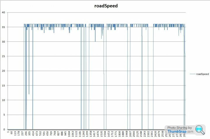
The test drive included a varying road speed range of 0 to 70 mph. The max value in the roadSpeed results column was 36 mph.
I've not data logged a TVR with the diff mounted speed sensor and TVR's splitter box before, so is this read out normal? If not could the splitter box be faulty?
The car is a Chimaera '97 400 and suffers from a sustained high idle (1400 rpm) when coming off the throttle, decelerating and coming to a halt.
It should be simpler than that- the speed reading is irrelevant as long as its 0 mph when it stops- and shows a speed when you are moving- thats all the ECU to know to put the car in idle mode- so whats the target RPM versus the real RPM and is the green idle mode light on when the cars stopped? Whats the stepper reading at idle, and is the base idle set correctly? Sorry if this is sucking eggs...
stevesprint said:
Mark
Here's the AFR for map 2 at a steady 60 mph and hopefully answers your question. It's great to see the AFR merged with RG without a time delay. The RoverGauge speedo it a bit random and usually over reads at low speed and then under reads at high speed.
Steve I'm a bit confused here, the MPH column in your table shows 22-25 yet you say the data was logged at 60MPH and that the RoverGauge speedo is not reading accurately but I assume was showing a reading somewhere in region of 60 or was it showing 22-25? Was the above data logged on your pre-cat with the Stevesprint speedo sensing circuit or a TVR with the splitter box arrangement?Here's the AFR for map 2 at a steady 60 mph and hopefully answers your question. It's great to see the AFR merged with RG without a time delay. The RoverGauge speedo it a bit random and usually over reads at low speed and then under reads at high speed.
#time         MPH    RPM    throttle   mafPercent   MapRow  MapCol  pulseMs   AFR
18:47:54.324   27   2274    0.198436    0.103297       1      9     3.18      14.5
18:47:54.829   27   2270    0.220919    0.132736       1      9     3.395     15.3
18:47:55.373   22   2267    0.231672    0.147253       1      9     3.617     15.5
18:47:55.988   22   2269    0.232649    0.1476         1      9     3.627     15.6
18:47:56.532   22   2275    0.232649    0.147947       1      9     3.631     15.6
18:47:57.012   22   2280    0.232649    0.1476         1      9     3.611     15.7
18:47:57.540   22   2288    0.232649    0.144939       1      9     3.623     15.7
18:47:58.100   24   2293    0.233627    0.145633       1      9     3.646     15.7
18:47:58.596   24   2299    0.236559    0.153094       1      9     3.668     15.7
18:47:59.107   24   2301    0.236559    0.152632       1      9     3.687     15.7
18:47:59.652   25   2308    0.236559    0.151938       1      9     3.666     15.6
18:48:00.186   25   2314    0.236559    0.149451       1      9     3.676     15.6
18:48:00.820   22   2324    0.236559    0.148409       1      9     3.626     15.5
18:48:01.370   22   2299    0.0537634   0.044013       0      9     1.894     14.2
18:48:01.876   25   2267    0.0537634   0.041642       0      9     1.956     13.5
Edited by stevesprint on Monday 2nd June 22:16
blitzracing said:
It should be simpler than that- the speed reading is irrelevant as long as its 0 mph when it stops- and shows a speed when you are moving- thats all the ECU to know to put the car in idle mode- so whats the target RPM versus the real RPM and is the green idle mode light on when the cars stopped? Whats the stepper reading at idle, and is the base idle set correctly? Sorry if this is sucking eggs...
Thanks Mark I was hoping someone could confirm that the roadSpeed graph was normal for a TVR with the splitter arrangement. The idle parameters all checked out fine because, as Sod's law would have it, the car wouldn't show the idling fault on the test run, so it was decided to do another RoverGauge session if and when the fault returns.In regard to the road speed signal chart above, I now think the results are as they should be for a car which has the TVR splitter unit in the speedo sensing circuit. Taking into account how rapid the drop to zero from 35/6, and vice versa, is when RPM drop or rise falls in very nicely with the TVR splitter unit's intended function. As far as we know the road speed does not have an impact on fuelling and only comes into play when being compared with the idle mode threshold, which is set at 4 MPH. So immediately the throttle is released the roadSpeed signal must drop rapidly from 36 MPH to zero past the 4 MPH threshold. I think the ceiling threshold is set at an 36 purposely to avoid transients triggering the idle mode and to realise an optimum response time.
Edited by davep on Sunday 8th June 10:58
davep said:
The test drive included a varying road speed range of 0 to 70 mph. The max value in the roadSpeed results column was 36 mph.
I've not data logged a TVR with the diff mounted speed sensor and TVR's splitter box before, so is this read out normal? If not could the splitter box be faulty?
DaveI've not data logged a TVR with the diff mounted speed sensor and TVR's splitter box before, so is this read out normal? If not could the splitter box be faulty?
This should answer your question
http://www.pistonheads.com/gassing/topic.asp?t=130...
and while searching I also came across this that you may also find interesting, I'm referring to TVR4ever's post half way down.
http://www.pistonheads.com/gassing/topic.asp?h=0&a...
stevesprint said:
Dave
This should answer your question
http://www.pistonheads.com/gassing/topic.asp?t=130...
and while searching I also came across this that you may also find interesting, I'm referring to TVR4ever's post half way down.
http://www.pistonheads.com/gassing/topic.asp?h=0&a...
Now you're just trying to wind me up with a confuse-a-Dave because of the Lexicon quip aren't you?This should answer your question
http://www.pistonheads.com/gassing/topic.asp?t=130...
and while searching I also came across this that you may also find interesting, I'm referring to TVR4ever's post half way down.
http://www.pistonheads.com/gassing/topic.asp?h=0&a...
TVR4ever's post is what I previously said on page 22 (post about half way down) of this thread...
and
blitzracing said:
It has two basic components- the first clocks the signal rate from the diff sensor and then switches on a basic pulse generator when the input signal is around 3mph. This pulse generator produces a signal that is around 35- 55mph that is then fed into the ECU. Its an all or nothing set up and pretty crude at best.
According to Mark's old explanation my roadSpeed chart above shows the output of the '35mph signal generator' to the ECU and that the road test was mainly done at a speed of 3mph. Edited by davep on Sunday 8th June 18:19
davep said:
Now you're just trying to wind me up with a confuse-a-Dave because of the Lexicon quip aren't you?
TVR4ever's post is what I previously said on page 22 (post about half way down) of this thread...
I remember your post on page 22 and that’s why I enclosed the link when I came across it while searching for the speedo interface box. I'm sorry if you think I'm trying to rev you up, but I'm sure you realise that's not my style. I didn't even read the post in detail as I was in a hurry.TVR4ever's post is what I previously said on page 22 (post about half way down) of this thread...
davep said:
Steve I'm a bit confused here, the MPH column in your table shows 22-25 yet you say the data was logged at 60MPH and that the RoverGauge speedo is not reading accurately but I assume was showing a reading somewhere in region of 60 or was it showing 22-25?
I don't know the RoverGauge speedo reading on the screen during the 60mph test as I had my eyes on the road, but I would trust Colin’s RoverGauge to log the displayed speed. The next time I'm out with my chief data logger operator I’ll ask her to keep an eye on both speedos. All I can tell you right now is my RoverGauge speedo reading is all over the place, sometime too high and sometimes too low. It use to bother me until I heard about the strobing issue and the speed is refreshed only ones a second. Is you RoverGauge speedo consistently half or do you experience the strobing issue as well.davep said:
Was the above data logged on your pre-cat with the Stevesprint speedo sensing circuit or a TVR with the splitter box arrangement?
NO, I do not have the TVR speedo interface box, all I have is a http://www.caigauge.com/page18.html and a propshaft crown wheel that I’ve reduced the number of teeth to 4 to match the calibration of my old LT77 speed sensor?stevesprint said:
... I'm sorry if you think I'm trying to rev you up, but I'm sure you realise that's not my style. I didn't even read the post in detail as I was in a hurry.
Steve, I wrote that with a big smile on my face, just joshing you. Just to reiterate, the LT77 gearbox mounted speedo sensor that TVR used was: orange, 20 tooth drive wheel, with either a 4-pulse/rev or 8-pulse/rev Hall effect sensor/switch. One way to tell them apart is to shine a light into a small aperture in the body of the sensor, turn the drive wheel one revolution and count the number of times the trigger blade passes the aperture. Another way is to run RoverGauge and check the roadSpeed values, if they are half of what you'd expect you have a 4-pulse, if full value then you have an 8-pulse.
So the fact that you have a speed sensing rig that emulates the 4-pulse/rev version explains why you have those low values in your MPH column plus your sensor may be the cause of the misreading. If you look back through this thread Dan gave a code fix to solve the 4-pulse/rev speedo misreading by half problem, which I implemented and the RoverGauge speedo now runs fine.
So for later RV8 TVRs with the speedo signal generator box in place the speedo in the RoverGauge display should only read out values typically in the range 0 to 36 mph, for example.
Update on the A/C and heated screen sense features: we observed some unexpected behavior regarding the A/C compressor load bit. It appears to represent a more complex condition than the compressor load, because it was toggling while the A/C was off. This needs more investigation before I release a new version.
cmb said:
Update on the A/C and heated screen sense features: we observed some unexpected behavior regarding the A/C compressor load bit. It appears to represent a more complex condition than the compressor load, because it was toggling while the A/C was off. This needs more investigation before I release a new version.
Colin, seriously don't bust a gut over the AC compressor load bit, it's not worth it especially at this time of year. Is the AC compressor load bit the same thing as the A/C load input on ATOC channel 6?davep said:
So the fact that you have a speed sensing rig that emulates the 4-pulse/rev version explains why you have those low values in your MPH column plus your sensor may be the cause of the misreading.
Oh Dave, I wish it were that simple RoverGauge has revealed a real can of worms with my road speed sensor to the point that I'm surprised I don't get a fault code. My ECU road speed is so bad I may have to try a different speed sensor.davep said:
If you look back through this thread Dan gave a code fix to solve the 4-pulse/rev speedo misreading by half problem, which I implemented and the RoverGauge speedo now runs fine.
DaveWhat revision have you implemented Dan's RoverGauge speedo fix in?
Anyone please help.
I'm starting to question my current speed sensor because when I changed from the LT77 speed sensor I had to remove the pull down resistor from the back of my programmable speedo as my new speed sensor has the pull down resistor build in. What does a pull down resistor do and would one in my road speed sensor be compatible with the 14CUX?
Also, should I be using a Hall effect speed sensor as my Caerbont EMP34-1 sensor is amplified inductive and outputs a true square wave. I’ve been informed the LT77 sensor is an open collector with a transistor amp, what ever that means.
Dan,
In the winter I'm now seriously considering installing the same Hamlin sensor as yours, therefore which version do you have, the 00 or the AP?
55075-00-02-A (Digital Output)
http://uk.farnell.com/hamlin/55075-00-02-a/sensor-...
55075-AP-02-A (Analogue Pulse)
http://uk.farnell.com/hamlin/55075-ap-02-a/sensor-...
Thanks in anticipation
Steve
Gassing Station | Griffith | Top of Page | What's New | My Stuff