Instructions to change fuel maps on 14CUX Griffith, Chimaera
Discussion


danbourassa said:
In open loop, software measures the CO trim voltage and stores the same value in both memory locations, however nothing is done with the values.
Dan, I’m really sorry for my persistence but please can you put my mind at reset and confirm if the code below is where the long term trim is used to adjust the injector pulse width.
;---------------------------------------------------------------------------------------------------
;                       Phase 2 Compensation (long term trim adjustment)
;
; The 16-bit long term trim value is applied here.
;
; One count is added or subtracted to the fueling value for every $80 (128 dec) counts from the 32K
; neutral point. The max adjustment is $00FF (positive) or $FF00 (negative). That equals +255 to
; -256 in decimal.
;
; During cranking a special fuel value is used and code jumps to here bypassing fuel map use,
; filtering and Phase 1 compensation.
;
; The data value at XC0A0 is actually a code control value that's used in several places in the
; software. Here, bit 7 is tested and if the value is zero, the long term trim adjustment is
; skipped. This value is normally $80, which enables the long term adjustment.
;
;---------------------------------------------------------------------------------------------------
.LE983          std         $00CC               ; store partially compensated fuel value in X00CC/CD

                ldaa        $C0A0               ; data value is $80 (code control byte)
                bpl         .LE9A8              ; msb set, so does not branch to next section

                ldd         longLambdaTrimR     ; load right long term trim value
                tst         $0088               ; test bank indicator bit
                bpl         .LE993              ; if right, branch to use this value

                ldd         longLambdaTrimL     ; else, load the left bank value

.LE993          asld                            ; double the value (msb into carry flag)
                tab                             ; xfer A to B (carry flag not affected)
                bcs         .LE9A3              ; branch if value was $8000 or higher

                ldaa        bits_008C           ; reduce fuel
                bita        #$08                ; test bits_008C.3 (this bit forces open loop)
                beq         .LE99F              ; if zero, branch to continue

                ldab        #$FF                ; create value of -1 ($FFFF), basically neutral

.LE99F          ldaa        #$FF                ; create negative value
                bra         .LE9A4              ; branch

.LE9A3          clra                            ; create positive value

.LE9A4          addd        $00CC               ; add adjustment to fuel value (range is +255 to -256)
                std         $00CC               ; store in-process fuel value
If this is the correct code please explain how it’s bypassed for map’s 1,2 & 3 ? I’m confident it’s not the bpl (Branch if Plus) on the third line down as prom offset $00A0 is $80 is every bin I’ve checked from old to Operation Pride.
Arrrr, I just had a thought does the code alter the bits of $C0A0 to turn off/on the long trim. I'll do some more digging but not tonight, in the mean time please don't spoil my fun, but I would appreciate a hint.
I’m really sorry if my little knowledge is dangerous but hopefully I'm starting to see the bigger picture.
Edited by stevesprint on Friday 31st October 00:07
danbourassa said:
The calculation to linearize the AFM is complicated but it's also important to get right since software uses the linearized value and not the direct value. A few months ago I bought a used Sagem 20AM to investigate the difference between the 5AM and the 20AM. My intent is to connect them both in series and run varying amounts of air through them while taking readings from both. If the differences are minor, I may be able to tweek the existing equation to get it close enough for the 20AM. Otherwise, there are math tools on the Internet to create best-fit equations for curves. Colin has used them so I might hand the data over to him to get the new equation.
But I may have a better way to handle this. I'm convinced that it's just through luck or accident that the 14CUX seems to function at TVR's 6000 plus RPM redlines. I have been looking for ways to save processing time in the code and since math is not this processor's strength, this is a good area to improve. Converting the linearization function from a calculation to a look-up-table will help. This is a trade off between processing time and memory use. There is not enough unused ROM memory to use a LUT for the whole 10-bit range, but there IS enough to use a LUT for the top half. And that is when the RPMs are highest.
I'm pretty sure Mark has done some extensive testing between these AFM's and the Bosch. I recall doing some graphs for him on Excel last year. It would be good to be able to easily mod the 20AFM. I'm really impressed with what you are all doing.But I may have a better way to handle this. I'm convinced that it's just through luck or accident that the 14CUX seems to function at TVR's 6000 plus RPM redlines. I have been looking for ways to save processing time in the code and since math is not this processor's strength, this is a good area to improve. Converting the linearization function from a calculation to a look-up-table will help. This is a trade off between processing time and memory use. There is not enough unused ROM memory to use a LUT for the whole 10-bit range, but there IS enough to use a LUT for the top half. And that is when the RPMs are highest.
stevesprint said:
If this is the correct code please explain how it’s bypassed for map’s 1,2 & 3 ?
Up to now, I believed that the CO trim varied the MAF voltage slightly to affect the mixture. Mark & Steve are saying that the mixture is affected by the CO trim voltage being measured and stored in the long term trim locations. I'm looking at the code listing again for the first time in months and guess what? I think you guys are correct!Steve, you lead me to this by asking how the long term trim is bypassed in maps 1,2 & 3. It appears that it's not bypassed. If I had payed more attention to my own flowchart, this may have dawned on me earlier. This all makes sense to me now that I stop and think about it. Mark, I apologize for insisting that the values were not used. This clears up a number of things for me. For example, why the trim value is shifted to become a signed number before being stored (see mafTrim.asm). Now I see that it's obviously done to allow bipolar adjustment of the long term trim. I'll also have to update my comments in this file and others. I feel foolish.
Steve, to answer the other part of your question, you are right about the byte at $C0A0. I believe this byte was a test and development aide for Lucas. I'm thinking that it allowed them to remove the long term trim when needed, in order to assist development of the basic map. There are other bits in $C0A0 that are used to potentially control other code.
Dan, I've been looking at the code involved in the selection of open and closed loop with a view to contributing to the CO trim issue above, and I've found this in the ICI loop between processes (9) and (10):
Does this mean, for instance, when map 5 is selected and with ECT below 50 deg C that open loop is selected and therefore ADC channel 9 comes into play? As a result, is the CO trim value now used to determine Lambda long term trim levels? If so, which one of the open loop map data sections provides the ADC table?
Steve when you did your proving of the CO trim values impacting Lambda long term trim what was the engine temperature, did you take RoverGauge screen shoots?
;------------------------------------------------------------------------------
;       Set or Clear X0087.0 which control Open/Closed Loop
;
; Normal path is from the bpl, just above to here. TPS being read and engine
; running. X0087.0 is set or cleared here. This bit is used for open/closed
; loop control. (bit is set when TPS > 40% and ECT cooler than 122 F)
;------------------------------------------------------------------------------
.LDD22          subd        #$019A              ; subtract 410 dec from TPS (40% or 2.0 volts)
                bcs         .LDD33              ; branch ahead to clr bit if TPS < 2.0 volts

                ldaa        coolantTempCount    ; load ECT sensor count
                cmpa        #$51                ; compare with $51
                bcs         .LDD33              ; branch ahead if ECT hotter than 50 C (122 F)

                ldaa        $0087
                oraa        #$01                ; set X0087.0 (to force open loop)
                bra         .LDD37

.LDD33          ldaa        $0087               ; if here, conditions are OK for closed loop
                anda        #$FE                ; clr X0087.0 (to allow closed loop)

.LDD37          staa        $0087               ; store it
Does this mean, for instance, when map 5 is selected and with ECT below 50 deg C that open loop is selected and therefore ADC channel 9 comes into play? As a result, is the CO trim value now used to determine Lambda long term trim levels? If so, which one of the open loop map data sections provides the ADC table?
Steve when you did your proving of the CO trim values impacting Lambda long term trim what was the engine temperature, did you take RoverGauge screen shoots?
davep said:
Does this mean, for instance, when map 5 is selected and with ECT below 50 deg C that open loop is selected and therefore ADC channel 9 comes into play? As a result, is the CO trim value now used to determine Lambda long term trim levels? If so, which one of the open loop map data sections provides the ADC table?
Dave $09 (channel 9) is not in MAP 5's ADC Mux table therefore I don’t think. I’ve been learning from my mistakes when I copied a Map2 ADC mux table into Map5 that I’m sure Dan remembers.I'm guessing the open and closed loop code you refer to is used to stop the trims being calculated in the first place and not whether the trims are taken into account when calculating the pulse width. Therefore below 50 degs I assume the code will carry on using the last know trim values.
stevesprint said:
Dave $09 (channel 9) is not in MAP 5's ADC Mux table ...
Steve, I know it isn't, that was my question. To repeat, if you have map 5 selected according to the above condition flag setting code the system will not go into closed loop until ECT is 50 deg C or if the ECT value is below 50 deg C, instead the system is set for open loop. So does one of the open loop maps and its ADC table now including channel 9 come into play, if so which?stevesprint said:
I'm guessing the open and closed loop code you refer to is used to stop the trims being calculated in the first place and not whether the trims are taken into account when calculating the pulse width. Therefore below 50 degs I assume the code will carry on using the last know trim values.
I'll have to think about that since there are other areas of code that handle open or closed loop conditions?I'm in the process of tabulating the conditional flags held in $0085.1 to $008C.7 as they may make the situation clearer.
davep said:
Does this mean, for instance, when map 5 is selected and with ECT below 50 deg C that open loop is selected and therefore ADC channel 9 comes into play? As a result, is the CO trim value now used to determine Lambda long term trim levels? If so, which one of the open loop map data sections provides the ADC table?
Dave, I have never seen a closed loop map that measures ADC channel 9. My conclusion was that CO trim is unmeasured and cannot affect software in closed loop mode. Also, I have never seen any evidence in the code of another ADC control list coming into play.I was awake half the night thinking about CO trim vs. self-adjusting trim. Up to now, I believed they had to be mutually exclusive. I went back and re-read the "Graphics interface for the 14CUX" thread. This is the original RoverGauge thread and it has a lot of info that's still useful. This is about the time when we were first becoming aware of long term trim. Here I'm quoting Jools:
Blitz .. When I was with John Ravenscroft (ex TVR factory engine guru) he was with me in a chimaera with his (presumably lucas developer) software running .. and there's a fuel trim learned when the car is stationary, at idle, with full working temperature and stable idle and throttle inputs at idle. The ecu then learns a trim which is applied over the whole rev range. live lambda trimming is then applied on top of that trim. It's the long term adapted trim learned at idle that's cleared by disconnecting the ecu. This is what he described to me 15+ years ago so i hope I remembered it correctly.
I have no problem with what Jools is stating. I think he did remember it correctly. However, shortly after, Griffith_500 posted this:
I have had problems with rich running at start up, spitting fuel on the garage wall. When I looked at the Rovergauge I found that the long term compensation was at -100% on both lamdas. No fault codes and all sensors looked OK. I changed the CO voltage on the AFM from 1,8 V to 1,0 V, and now the long term compensation changed to +14 % on one lambda and -26 % on the other. Does this make any sense?
Obviously, Griffith_500 had to be running closed loop, otherwise the long term trim values would be identical. Software has to be adjusting them independently based on Lambda stats. But, in closed loop, the ADC channel 9 measurement is not done, or at least, I've never seen it in a closed loop ADC control table. This is one of the statements that lead me to believe that the CO trim affects the mixture in some other way, such as letting in more or less unmetered air. I'm confused.
danbourassa said:
Up to now, I believed that the CO trim .........
stevesprint said:
(June 2013)
Dan, Your a total and utter genius.
I've changed my comparator .. in RoadSpeed.asm ...... and now my RoverGauge speedo finally works.
Dan Dan, Your a total and utter genius.
I've changed my comparator .. in RoadSpeed.asm ...... and now my RoverGauge speedo finally works.
You'll always be the 14CUX genius who freed the 14CUX and that will be your legacy forever.
You have reversed engineered, commented and understood about 20,000 lines of code which very few people appreciate the scale of the code. It's less hard for me to pick on one small point that I'm completely obbsessed with.
Lucus would of had a whole team but we are better off as we have you doing it for a labour of love.
Keep up the grand work we all really appreciate it.
Edited by stevesprint on Saturday 1st November 00:07
Apologies, I mistakenly thought a system with a closed loop map when going into open loop would use an open loop fuel and/or data section. So in RoverGauge how come the Lambda trim values are displayed and adjusted when a closed loop system is in open loop, i.e. during engine warm up until ECT is 50 deg C and when MAF voltage is > 2Vdc?.
davep said:
Steve, I know it isn't, that was my question.
Sorry, Dave,I know you know especially as you’re the one that taught me how the Mux tables work, I didn’t realise you where thinking outside the box, not literally.
I’m just delighted we are making more discoveries and once again have yourself and Dan back in the 14CUX driving seats. It's great how dangling a few lines of code catches our attention.
stevesprint said:
Sorry, Dave,
I know you know especially as you’re the one that taught me how the Mux tables work, I didn’t realise you where thinking outside the box, not literally.
I’m just delighted we are making more discoveries and once again have yourself and Dan back in the 14CUX driving seats. It's great how dangling a few lines of code catches our attention.
I know Steve, good isn't it!I know you know especially as you’re the one that taught me how the Mux tables work, I didn’t realise you where thinking outside the box, not literally.
I’m just delighted we are making more discoveries and once again have yourself and Dan back in the 14CUX driving seats. It's great how dangling a few lines of code catches our attention.
Looks like Dan's become a insomniac just like me.
I appreciate I've stated the obvious but I'm just trying to get to the reason why the CO trim level should impact on the Lambda trim levels and AFR in closed loop. I think this one might be a bit of a challenge and certainly time consuming.
davep said:
Apologies, I mistakenly thought a system with a closed loop map when going into open loop would use an open loop fuel and/or data section. So in RoverGauge how come the Lambda trim values are displayed and adjusted when a closed loop system is in open loop, i.e. during engine warm up until ECT is 50 deg C and when MAF voltage is > 2Vdc?.
Dave, I think you realize now that this is not the same kind of open loop as an open loop map. It's similar to when a closed loop map becomes open at about 3400 RPM. There are a number of conditions that can suspend the application of the trim values temporarily. Neither the map nor the ADC table change. RoverGauge still displays the closed loop setup since the 14CUX can go back to active closed loop at any time.Chuffmeister said:
danbourassa said:
The calculation to linearize the AFM is complicated but it's also important to get right since software uses the linearized value and not the direct value. A few months ago I bought a used Sagem 20AM to investigate the difference between the 5AM and the 20AM. My intent is to connect them both in series and run varying amounts of air through them while taking readings from both. If the differences are minor, I may be able to tweek the existing equation to get it close enough for the 20AM. Otherwise, there are math tools on the Internet to create best-fit equations for curves. Colin has used them so I might hand the data over to him to get the new equation.
But I may have a better way to handle this. I'm convinced that it's just through luck or accident that the 14CUX seems to function at TVR's 6000 plus RPM redlines. I have been looking for ways to save processing time in the code and since math is not this processor's strength, this is a good area to improve. Converting the linearization function from a calculation to a look-up-table will help. This is a trade off between processing time and memory use. There is not enough unused ROM memory to use a LUT for the whole 10-bit range, but there IS enough to use a LUT for the top half. And that is when the RPMs are highest.
I'm pretty sure Mark has done some extensive testing between these AFM's and the Bosch. I recall doing some graphs for him on Excel last year. It would be good to be able to easily mod the 20AFM. I'm really impressed with what you are all doing.But I may have a better way to handle this. I'm convinced that it's just through luck or accident that the 14CUX seems to function at TVR's 6000 plus RPM redlines. I have been looking for ways to save processing time in the code and since math is not this processor's strength, this is a good area to improve. Converting the linearization function from a calculation to a look-up-table will help. This is a trade off between processing time and memory use. There is not enough unused ROM memory to use a LUT for the whole 10-bit range, but there IS enough to use a LUT for the top half. And that is when the RPMs are highest.

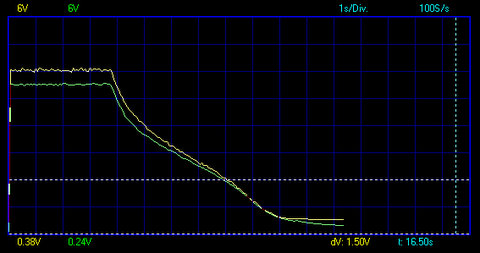
Green trace 20 AM, yellow 5AM
 |http://thumbsnap.com/DMSUttns[/url]
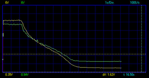
The Bosch is more complex as the response is skewed
 [url]
[url]Green trace Bosch, yellow 5AM
stevesprint said:
Mark and I have proved the CO trim effects the AFR up to 3,000+ rpm when running the non-cat map (similar to lambda control) and also when switching from non-cat to cat map the Lambda long term trim is reset according to the CO trim value ...
Furthermore we also know the CO trim and Lambda long term trim are stored in the same memory address which proves the CO trim is adjusting the lambda long term trim.
Ok, the penny has now dropped! You set the three CO trim pot values each time in open tune and switched from the open loop fuel map/data section to closed loop tune and THEN checked the Lambda trim values.Furthermore we also know the CO trim and Lambda long term trim are stored in the same memory address which proves the CO trim is adjusting the lambda long term trim.
Edited by stevesprint on Wednesday 29th October 20:55
davep said:
Ok, the penny has now dropped! You set the three CO trim pot values each time in open tune and switched from the open loop fuel map/data section to closed loop tune and THEN checked the Lambda trim values.
Sorry I tuned out during all the excitement to take my daughter out trick or treating.Dave, yes that's correct.
My tests on the previous page are misleading, as I never explained that the engine was stone cold and not even running. I was only trying to prove the CO trim scale is the same as the long term trim scale plus the CO trim value is carried over to map 5 lambda trim when switching maps.
To reproduce my tests you first need to fire up and then stall the engine to load the currently selected map’s ADC mux table, I wonder who taught me that trick, in this case select map 2. Now as you turn the CO trim screw you’ll see in real time the CO trim voltage change in RoverGauge and if you now switch to map 5 you’ll also see the long term lambda trim change in real time.
Restarting the engine will reload the currently selected map’s ADC mux table that also demonstrates to change maps you have to at a minimum stall and restart the engine. After switching to map 5 and restarting the code will use the trim values at longLambdaTrimR and longLambdaTrimL regardless if they were last set via map 5 lambda code or map 2 CO trim code.
Sorry if I caused you and Dan sleepless night but hopefully we can now finally put this one to bed so we can all now sleep at night.
Edited by stevesprint on Saturday 1st November 00:41
danbourassa said:
Steve, to answer the other part of your question, you are right about the byte at $C0A0. I believe this byte was a test and development aide for Lucas. I'm thinking that it allowed them to remove the long term trim when needed, in order to assist development of the basic map. There are other bits in $C0A0 that are used to potentially control other code.
Could we also use $C0A0 (Prom offset $00A0) to remove the CO trim with map 2 while working on a map. I realise this is not the most efficient approach for map 5 as the long term will still be calculated with map 5 and then not used, I bit like TVRs approach to removing the road speed limiter. Also, it could be misleading as RoverGauge will show the long term trim changing but the code will not actually be using the trim. Plus lets not even think about the short term trim.If not would it be safe to remove the CO trim channel from the map 2 ADC mux list??
I’ll have to give both approaches ago with open and closed maps before the winter. It will also be interesting to see if the short term trims still works with map 5.
Now look who can't sleep, lol.
Edited by stevesprint on Saturday 1st November 01:17
danbourassa said:
Mark, if I make code changes for the 20AM, should I also do the Bosch unit? Are there advantages to the Bosch?
The 20AM is no longer available new, where as the Bosch is. Otherwise the wiring is simpler on the 20AM, as it does not need a 5 volt rail. The Bosch has a 12 and a 5 volt input, and certainly in the past great effort has been made to get a 5 volt supply from the ECU to this pin, but TBH I dont think its actually needed but I need to double check this however. Personally I think a simple 5 volt regulator from the 12 v supply would be far better than messing around with the ECU loom if it is needed.stevesprint said:
To reproduce my tests you first need to fire up and then stall the engine to load the currently selected map’s ADC mux table, I wonder who taught me that trick, in this case select map 2. Now as you turn the CO trim screw you’ll see in real time the CO trim voltage change in RoverGauge and if you now switch to map 5 you’ll also see the long term lambda trim change in real time.
You say real time but when you switched to map 5 the long term Lambda trim didn't change with any further adjustment to the CO trim pot, right?Edited by stevesprint on Saturday 1st November 00:41
stevesprint said:
Please can you help me understand, in the code, how the Lambda long term trim/CO trim is taken into account when calculating the injector pulse width when running the non-cat map. I’m sure you realise I’m ultimately trying to prove copying a cat map to a non-cat map is an effective way to turn off automatic Lambda control and instead have manual lambda control.
I hope I've understood this correctly but to get manual control couldn't you simply insert channel 9 into a cat map's ADC Mux table and set the control code at XC0A0 to $00? You'd have to check the implications of setting XC0A0 in this way as it's used elsewhere. Might be good time to invest in a Logic Analyser.
Edited by davep on Saturday 1st November 11:43
Gassing Station | Griffith | Top of Page | What's New | My Stuff