Instructions to change fuel maps on 14CUX Griffith, Chimaera
Discussion


stevesprint said:
Dave $09 (channel 9) is not in MAP 5's ADC Mux table therefore I don’t think. I’ve been learning from my mistakes when I copied a Map2 ADC mux table into Map5 that I’m sure Dan remembers.
Steve, yes I do remember when you did this and I suspected that this is what you did again this time. However, there appears to be more than one way to couple an open-loop ADC table with a closed loop map. When you change maps by changing tune resistor with power on, the fuel map part will change but the ADC table will not change until the ECU gets a spark from the engine. We touched on this subject earlier in this thread. This allows you to create open/closed hybrid maps momentarily. Of couse, as soon as the engine is started, the map is re-synchronized. This may or may not explain what happened to Griffith_500 but I'm not going to worry too much about that. I'm now convinced that the CO trim is the open loop equivalent of the long term trim. Adjusted manually by the user but applied by software in the same way.This also explains why the effect of the CO trim gradually diminishes as load and RPMs rise. Other fueling modifiers in the code multiply the fuel value by a factor. This affects the fueling over the whole range. For example, a 10% increase in fuel is still 10% whether at idle or full throttle at the RPM limit. However, CO/long-term trim is calculated and applied differently. The range is -256 counts to +255 counts of fuel adjustment.
CO trim = 0.00 volts gives 100% reduction = -256 counts
CO trim = 2.50 volts gives 100% increase = +255 counts
Since the adjustment value is fixed, it becomes a smaller and smaller percentage of the fueling as the overall fuel number increases.
davep said:
I hope I've understood this correctly but to get manual control couldn't you simply insert channel 9 into a cat map's ADC Mux table and set the control code at XC0A0 to $00? You'd have to check the implications of setting XC0A0 in this way as it's used elsewhere.
DaveInteresting idea, we need to prove if XC0A0 = $00 not only stops the trims being applied to the injector pulse width but also if it stops the trims being calculated.
Therefore we don't know if inserting channel 9 into a cat map's ADC Mux table with XC0A0 = $00 would or wouldn't stop the CO trim ADC service and the lambda routine in ICI to constantly overwrite each others setting as they share the same memory address. (longLambdaTrimR & longLambdaTrimL). It would of been good if we could have just removed a lambda service or two from the mux table, but as you know it not a service in the mux list. I'll try copying map2's mux table to map5's mux table with XC0A0 = $00. When I previously copied map2 mux to map5 mux in error over 6 months ago I remember the CO trim did adjust the long trim when the engine wasn't running, but I can't remember what happened with the short trim. I'll have to give it ago but with XC0A0 = $00.
davep said:
You say real time but when you switched to map 5 the long term Lambda trim didn't change with any further adjustment to the CO trim pot, right?
Surprisingly the long term did change with further adjustment of the CO trim, remember map2’s mux table stays active until the engine is fired up again. I'll test to see if it takes a spark interrupt or does the engine need to actually run ie 375rpm with R3652 or 505rpm with R2967.danbourassa said:
Steve, yes I do remember when you did this and I suspected that this is what you did again this time.
Actually, I didn't need to as map2’s mux table stays active until the engine is fired up again. This behaviour is exactly as per your description on the 20th March 2014 and I now see you have explained it again today in more detail, thanks. I like your recent description and it's very accurate “This allows you to create open/closed hybrid maps momentarily”.danbourassa said:
I'm now convinced that the CO trim is the open loop equivalent of the long term trim. Adjusted manually by the user but applied by software in the same way.
Excellent news and thanks for the confirmation. This confirms copying map5 to map2 and setting the CO Trim to 1.25v (the mid point) is an effective way to disable lambda control.
Furthermore, yesterday I went for a drive with the below map 2 mux table that I removed the CO trim service from. Luckily the CO Trim defaulted to the mid point of 1.25 volts and the CO trim screw had no effect on the CO trim voltage or the AFR.
LC473 DB $87,$86,$02,$03,$84,$02,$8D,$88,$02,$8B,$80,$85,$81,$8E,$FA,$FA ; ADC
I now realise the Mux table I just created above is identical to the map5 mux table, at least we now know the CO trim is the only difference between map2 and map5's mux tables.
I also had a quick test with prom offset $00A0 set to 00. With map 2 the CO trim screw had very little effect on the AFR (13.5 with 2.5 volts and 13.8 with 0.0 volts). Strange as it was bang on 13.5 when I removed the CO trim service from the previous test, maybe the cooling fans or headlamps could have effected the results.
I was then very surprised with the following results when I ran XC0A0 = $00 with a standard map 5
Dan, I agree it certainly looks like a development code flow control flag. It may help you understand whats going on to know both long trims started in the middle and then moved slowly in opposite directions at the normal speed, it looked Spooky !! Their was no fault codes and my long trims would normally be no worse than even +36% and odd –19%. I ran the test several times with different CO trim values which seem to of caused different results. It was almost as though the CO trim was playing a part in the results but I don't understand how when the CO trim isn't in map5's mux table, I will double check my bin file. I really don't know what to think, so if it helps I'll happily test it further for you.
Edited by stevesprint on Monday 3rd November 07:29
I'll next test Dave's suggestion to insert channel 9 into a cat map's ADC Mux table and set the control code at XC0A0 to $00, but thinking about this it would give you manual control of the long trims but then the long trims wouldn't be applied. We shall see.
Edited by stevesprint on Monday 3rd November 07:29
Dan, any ideas as to why Lambda readings are attempted with an open loop map 1, 2 or 3 selected and no sensors fitted:
Also why the 'if open loop branch/jump' is done in two stages:
bcs .LE0C6 ; branch if fuel map number is less than 4
... and ...
.LE0C6 jmp .LE523 ; jump label for skipping closed loop
;-------------------------------------------------------------------------------
;                     Open Loop Map Destination
;
; Fuel maps 1, 2 and 3 jump here immediately after the HO2 ADC measurement.
; Closed loop maps also jump here when conditions require open loop.
; Closed loop maps, running in closed loop, eventually get here too.
;
;------------------------------------------------------------------------------
Also why the 'if open loop branch/jump' is done in two stages:
bcs .LE0C6 ; branch if fuel map number is less than 4
... and ...
.LE0C6 jmp .LE523 ; jump label for skipping closed loop
davep said:
Dan, any ideas as to why Lambda readings are attempted with an open loop map 1, 2 or 3 selected and no sensors fitted
No, I don't know why. Both short and long term trim are also applied in open loop. Of course, we now know that long-term becomes the CO trim. Short term is forced to the neutral value of $8000 before it's applied so whatever garbage value is read by the Lambda channel is ineffective anyway.davep said:
Also why the 'if open loop branch/jump' is done in two stages
I think it's because branch type instructions are always preferable to use but have limitations in reach. They can be conditional which is more efficient than doing a separate test and then branching to avoid a jump. They have a single byte operand instead of the jmp instruction's two byte operand, so they execute faster and take up less code space. However, the branch works as a relative instruction. It moves forward or backward in code relative to the current position. And since the operand is a single signed byte, its reach is only from +255 to -256 (funny how those numbers come up again so soon). Since the jump instruction has a 2-byte operand, it can move to any point in the memory space.In this case, we have a number of conditional branches that branch to a local jump instruction that's within reach. The ultimate jump destination is out of the reach (I assume) of any of the individual branch instructions. By the way, any assembler will flag an error when you try to branch too far, but I don't know if they will alert you if you use a JMP where a BRA will work.
davep said:
Forgot to previously ask how Colin's MEMS project is going, is it generating the same level of interest as 14CUX? Should be plenty of Mini owners out there wondering what's going on within the EMS.
It hasn't taken off like RoverGauge but it is slowly gaining attention and he's starting to get emails about it. Although there are plenty of Minis out there, I think those with MEMS and single point injection are in the minority.Dave,
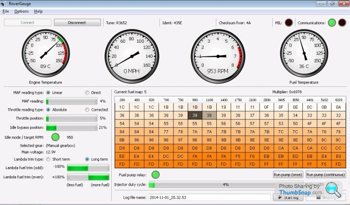
Map 5 plus CO trim in mux table & prom offset $00A0 = 00
I deliberately set the CO trim to 2.5v which you can see forced the long trim to +100%. I’m confident the long trim wasn’t applied to the injector pulse calculations as the short trim was moving small amounts as normal. It was unclear if the short trim was being applied to the injector pulse calculations but the AFR did move about slightly which is normal for map5. (Map2's AFR at idle is normally more stable than map5’s AFR)
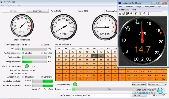
Map 5 plus CO trim in mux table & standard prom offset $00A0
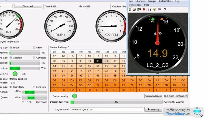
The long trim was forced to +100% as the CO trim voltage was 2.5v. As the long trim was being applied to the injector pulse calculations the short trim moved further negative than normal to compensate with a nett result of a normal AFR.
For both tests I let the engine idle for 4 minutes to give the long trim time to kick in and in both tests I never saw the long trim move away from 100%. Therefore I believe its safe to assume enabling the CO trim in map5 provides manual long term trim control but sadly it's unclear about the short term trim.
Map 5 plus CO trim in mux table & prom offset $00A0 = 00
I deliberately set the CO trim to 2.5v which you can see forced the long trim to +100%. I’m confident the long trim wasn’t applied to the injector pulse calculations as the short trim was moving small amounts as normal. It was unclear if the short trim was being applied to the injector pulse calculations but the AFR did move about slightly which is normal for map5. (Map2's AFR at idle is normally more stable than map5’s AFR)
Map 5 plus CO trim in mux table & standard prom offset $00A0
The long trim was forced to +100% as the CO trim voltage was 2.5v. As the long trim was being applied to the injector pulse calculations the short trim moved further negative than normal to compensate with a nett result of a normal AFR.
For both tests I let the engine idle for 4 minutes to give the long trim time to kick in and in both tests I never saw the long trim move away from 100%. Therefore I believe its safe to assume enabling the CO trim in map5 provides manual long term trim control but sadly it's unclear about the short term trim.
Steve great set of results and well described procedure, we'll have to start drilling down into the code to try and resolve some of the many CO trim:injection pulse width 'if-thens' and the associated variables.
One question: In the screenshots do the positions of the AFR meter max/min range indicators define the needle deflection for the same test conditions?
One question: In the screenshots do the positions of the AFR meter max/min range indicators define the needle deflection for the same test conditions?
Can I take two steps backwards then- so to recap the value of CO trim voltage is only set on the catalyst map as an initial long term trim value of effectively 0 until the lambda's kick in and reset it? It would account for the voltages specified by Mr Adams and the like, and why I never saw a change when winding the CO trim up and down whilst on Lamda control...
Steve, Dan, Dave - have been following the latest additions to this thread with interest. As Steve knows, after a link telephone conversation with him I tackled my first updated map on a spare 14CUX. My question is: all the latest thread messages discuss lambda and adjustment of CO and hence AFM trim within the 14CUX itself, do I take it this is for the later models with catalysts and Lambda sensors and NOT precats like my 4.3? Regards, Pete
Pete, CO trim and long term Lambda trim starts with the following chunk of code, which is run on pre-cat cars only as it is pointed to via a non-cat specific pointer in an ADC control table:
A 10 bit ADC value representing the voltage set by the CO trim pot on the AFM unit (common to non-cat and cat cars) is stored in memory at X00C8/9. The 10 bit value is shifted left seven times to locate its MSB into Carry and if normal the value is stored as the long trim variable in memory locations longLamdaTrimR/L. The question is are these values actually used on a non-cat tune other than to be sent out on the diagnostic interface and does the CO trim value have any impact on AFR in a cat car if a control flag and the ADC table are tweaked to allow the CO trim pot to set longLamdaTrimR/L.
Dan any idea what the 10 bit values will be for Steve's three test voltage levels?
Pete, have you posted the badges yet?
adcRoutine9     ldd         $00C8               ; load 10-bit value from X00C8/C9
                asld
                asld
                asld
                asld
                asld
                asld
                asld                            ; shift MSB into carry
                bcc         .msbLow             ; return if MSB was low (normal cond.)

                ldd         #$FFFF              ; bad value, store $FFFF instead

.msbLow         std         longLambdaTrimR
                std         longLambdaTrimL
                rts
A 10 bit ADC value representing the voltage set by the CO trim pot on the AFM unit (common to non-cat and cat cars) is stored in memory at X00C8/9. The 10 bit value is shifted left seven times to locate its MSB into Carry and if normal the value is stored as the long trim variable in memory locations longLamdaTrimR/L. The question is are these values actually used on a non-cat tune other than to be sent out on the diagnostic interface and does the CO trim value have any impact on AFR in a cat car if a control flag and the ADC table are tweaked to allow the CO trim pot to set longLamdaTrimR/L.
Dan any idea what the 10 bit values will be for Steve's three test voltage levels?
Pete, have you posted the badges yet?
Edited by davep on Tuesday 4th November 22:45
davep said:
Steve great set of results and well described procedure, we'll have to start drilling down into the code to try and resolve some of the many CO trim:injection pulse width 'if-thens' and the associated variables.
Dave Thanks, In case you haven't noticed I thoroughly enjoy testing and investigation the 14CUX, I’m not sure why but it does give me a lot pleasure. Sadly I'm starting to run out of testing opportunities as it’s getting colder, wetter and the nights are drawing in. BUT the good news is we’ll have more time to investigate all those 'if-thens' in the code. Plus when it’s snowing I plan to finish the AFR & RoverGauge log merger.
davep said:
One question: In the screenshots do the positions of the AFR meter max/min range indicators define the needle deflection for the same test conditions?
Good point, please ignore the AFR gauge max/min pointers as I don't normally use the LogWorks on screen AFR gauge and therefore only noticed them myself while posting these screen shots. I normally use my favourite gauge below but unfortunately it doesn’t have a print screen button.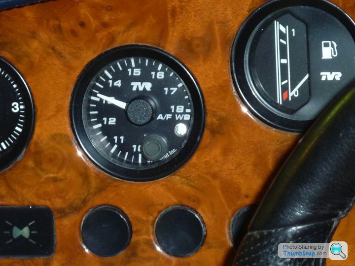
blitzracing said:
Can I take two steps backwards then- so to recap the value of CO trim voltage is only set on the catalyst map as an initial long term trim value of effectively 0 until the lambda's kick in and reset it? It would account for the voltages specified by Mr Adams and the like, and why I never saw a change when winding the CO trim up and down whilst on Lamda control...
Mark, Taking three steps back and ignoring all my recent bodges everything you already know and taught us about the CO Trim is still correct. Mark Adams must be specifying a CO trim voltage in case the non cat map is used.To confirm the CO trim voltage is completely ignored by the cat map and is not used as a starting point before the long term trims kick in. I’ve bodged a cat map to enable the AFM CO trim and it was interesting to note the AFM CO trim screw took priority over the normal cat map lambda long term code even at idle after 2 minutes.
PeteGriff said:
My question is: all the latest thread messages discuss lambda and adjustment of CO and hence AFM trim within the 14CUX itself, do I take it this is for the later models with catalysts and Lambda sensors and NOT precats like my 4.3? Regards, Pete
The major break though is that Dan has confirmed the AFM CO trim screw effectively provides Precat owners manual control of the Lambda long term trim and therefore its important to set is correctly. In addition we have found a safe way to disable the CO Trim for Precats that defaults to the mid point of 1.25 volts, whooopy.stevesprint said:
...In addition we have found a safe way to disable the CO Trim for Precats that defaults to the mid point of 1.25 volts, whooopy.
So Steve, is this 'disable default mid point trim' part of the updated 'map' that I am currently using (latest version from you for 430), or is it yest to be incorporated? Regards, Peteblitzracing said:
Why would you want to disable or preset via software the CO trim in any form on the non cat map? Its there to allow the car to pass the MOT emissions with a quick tweak if needs be.
Mark,I actually tend to agree with you. Why remove the flexibility of the CO trim especially when you can manually set it to the default mid point of 1.25v yourself.
However a few Precat owners have confirmed their 430 seems to run better when the CO trim is set near the mid point plus I've heard a few people complaining about bad running just because the CO trim was set incorrect.
Therefore as standard 430's run best with the default setting I’ll happily have two version of the 430 chip, one with and one without the CO trim enabled to make it easier and safer for people without a multi-meter, RoverGaugeor or the correct imperial allen key. Furthermore I'm sure you wouldn't want my 430 chip getting a bad review just because someones CO trim was set incorrectly.
Here's a thought I could disable the CO trim in Map 1 and leave it working in Map2 and that way we'll have the best of both world.
I’ll create the 430 chip with the disabled CO trim as soon as the first person asks for it.
Edited by stevesprint on Wednesday 5th November 23:58

stevesprint said:
Mark,
I actually tend to agree with you. Why remove the flexibility of the CO trim especially when you can manually set it to the default mid point of 1.25v yourself.
However a few Precat owners have confirmed their 430 seems to run better when the CO trim is set near the mid point plus I've heard a few people complaining about bad running just because the CO trim was set incorrect.
Therefore as standard 430's run best with the default setting I’ll happily have two version of the 430 chip, one with and one without the CO trim enabled to make it easier and safer for people without a multi-meter, RoverGaugeor or the correct imperial allen key. Furthermore I'm sure you wouldn't want my 430 chip getting a bad review just because someones CO trim was set incorrectly.
Here's a thought I could disable the CO trim in Map 1 and leave it working in Map2 and that way we'll have the best of both world.
I’ll create the 430 chip with the disabled CO trim as soon as the first person asks for it.
You want a guinea pig?I actually tend to agree with you. Why remove the flexibility of the CO trim especially when you can manually set it to the default mid point of 1.25v yourself.
However a few Precat owners have confirmed their 430 seems to run better when the CO trim is set near the mid point plus I've heard a few people complaining about bad running just because the CO trim was set incorrect.
Therefore as standard 430's run best with the default setting I’ll happily have two version of the 430 chip, one with and one without the CO trim enabled to make it easier and safer for people without a multi-meter, RoverGaugeor or the correct imperial allen key. Furthermore I'm sure you wouldn't want my 430 chip getting a bad review just because someones CO trim was set incorrectly.
Here's a thought I could disable the CO trim in Map 1 and leave it working in Map2 and that way we'll have the best of both world.
I’ll create the 430 chip with the disabled CO trim as soon as the first person asks for it.
Edited by stevesprint on Wednesday 5th November 23:58
FFG
Gentlemen,I have been reading this topic now for some time and decided that I would like to make a start on my project.
Sadly I appear to have fallen at the first hurdle in that I have taken a working 14cux and converted it to what may be scrap.
I removed the original fuel eprom and fitted a socket for the supposedly good tvr eprom I was given.
I tried it in the car but got no initial fuel pump run on ignition on.
My Rovergauge would not connect to it(did before)so I assume I have done some damage to the board.
My question is this.Will Rovergauge connect to a 14cux without the fuel eprom fitted?
There is a chance(I hope)that the tvr eprom is faulty and this might let me know if the ecu is still good.
By the way,I removed the old eprom by snipping the pins off and desoldering the circuit board,this way I did not have to lean on any other components.
Sorry to bother you but I would be grateful for any help on this .
Thanks in advance JJ.
jjohnson23 said:
Gentlemen,I have been reading this topic now for some time and decided that I would like to make a start on my project.
Sadly I appear to have fallen at the first hurdle in that I have taken a working 14cux and converted it to what may be scrap.
I removed the original fuel eprom and fitted a socket for the supposedly good tvr eprom I was given.
I tried it in the car but got no initial fuel pump run on ignition on.
My Rovergauge would not connect to it(did before)so I assume I have done some damage to the board.
My question is this.Will Rovergauge connect to a 14cux without the fuel eprom fitted?
There is a chance(I hope)that the tvr eprom is faulty and this might let me know if the ecu is still good.
By the way,I removed the old eprom by snipping the pins off and desoldering the circuit board,this way I did not have to lean on any other components.
Sorry to bother you but I would be grateful for any help on this .
Thanks in advance JJ.
Hi JJ, they say that hindsight is a wonderful thing, I like you have recently taken to 'having a play with alternative fuel maps, but decided to go down the route of buying a spare 14CUX to do it! It cost £70 delivered, but was well worth it as it was a later version, in mint condition and already had the EProm socket fitted into the PCB (a later Land Rover addition). Firstly to try and help; check carefully that you have not left any small solder bridges across any pins where you have soldered the socket, ensure you have soldered all the pins satisfactorily, but as a word of warning DO NO APPLY TOO MUCH HEAT for too long, you should ideally be using a lower temperature bit in the iron and it should be a fine tip type. If all that is ok as far as you can see ensure that the EProm you have fitted is in correctly (is it around the right way) as they have an orientation indent. Finally ensure all connection plugs are securely fitted and fully home. If no joy replace the EProm with your original and try again. If none of this works you either have damaged your ECU or there is another silly gremlin causing the issue. Sadly I appear to have fallen at the first hurdle in that I have taken a working 14cux and converted it to what may be scrap.
I removed the original fuel eprom and fitted a socket for the supposedly good tvr eprom I was given.
I tried it in the car but got no initial fuel pump run on ignition on.
My Rovergauge would not connect to it(did before)so I assume I have done some damage to the board.
My question is this.Will Rovergauge connect to a 14cux without the fuel eprom fitted?
There is a chance(I hope)that the tvr eprom is faulty and this might let me know if the ecu is still good.
By the way,I removed the old eprom by snipping the pins off and desoldering the circuit board,this way I did not have to lean on any other components.
Sorry to bother you but I would be grateful for any help on this .
Thanks in advance JJ.
When I tried to a new fuel map recently my Griff started and ran perfectly, this was using my acquired second ECU as described above. Don't panic, if all else fails just get your self a spare 14CUX, I can give you details of the Land Rover breaker that mine came from (they have an Ebay shop). Good luck, Pete
Gassing Station | Griffith | Top of Page | What's New | My Stuff