Instructions to change fuel maps on 14CUX Griffith, Chimaera
Discussion


stevesprint said:
Dave
Although first compare is with the second column the first column’s row 2 and 3 come into play and are used to create the beginning of the graph. This means the compare is always one column ahead of the active column. The last column is used to create the last section of the graph.
Its hard coded so the first 2 columns increase and the remaining 7 columns decrease, see the following compare and branch.
Compare B cmpb #$08 ; compare index counter with 8
Branch if Carry Set bcs .LF9BC ; branch ahead if B is < 8
I see it now Steve, thanks. I've looked back at the original data table handling posts, how Dan deciphered table handling from just raw Assembler code I just don't know.Although first compare is with the second column the first column’s row 2 and 3 come into play and are used to create the beginning of the graph. This means the compare is always one column ahead of the active column. The last column is used to create the last section of the graph.
 Row    Function
  1     Coolant temperature (Compared one ahead)
  2     Column starting Y Axis
  3     Rate of increase or decrease to the right (00 is flat)
Its hard coded so the first 2 columns increase and the remaining 7 columns decrease, see the following compare and branch.
Compare B cmpb #$08 ; compare index counter with 8
Branch if Carry Set bcs .LF9BC ; branch ahead if B is < 8
stevesprint said:
Dan, Dave or Colin
I've been asked if a 512K EPROM with 4 prom images would work in the 14CUX or would it be safe to try?
Cheers
Steve
Steve, sorry for the late response on this.I've been asked if a 512K EPROM with 4 prom images would work in the 14CUX or would it be safe to try?
Cheers
Steve
When the 32K PROM (27C256) was introduced and quickly replaced the 16K (27C128) it was compatible by design because the /PGM input was re-assigned to the additional address line (A14) which was needed. This program pin was already hardwired high in the circuit board because /PGM is active-low. This is why only the upper half of the 32K PROM is accesible in the 14CUX.
This compatibility approach was continued with the 64K PROM (27C512). In this case, the Vpp input which is normally held at +5 volts was reassigned to the additional address line (A15). This would mean that only the top 16K of the 64K PROM would be used but it should work.
Dave, the reason one would want to do this is the same as using the 32K PROM in place of the 16K. The earlier chips are actually harder to find and can be more expensive than the later, larger devices.
danbourassa said:
Steve, sorry for the late response on this.
When the 32K PROM (27C256) was introduced and quickly replaced the 16K (27C128) it was compatible by design because the /PGM input was re-assigned to the additional address line (A14) which was needed. This program pin was already hardwired high in the circuit board because /PGM is active-low. This is why only the upper half of the 32K PROM is accesible in the 14CUX.
This compatibility approach was continued with the 64K PROM (27C512). In this case, the Vpp input which is normally held at +5 volts was reassigned to the additional address line (A15). This would mean that only the top 16K of the 64K PROM would be used but it should work.
Dave, the reason one would want to do this is the same as using the 32K PROM in place of the 16K. The earlier chips are actually harder to find and can be more expensive than the later, larger devices.
Dan, I read the question as "can four (16K) PROM images be placed together in a 512K chip and somehow be selectable?". I assumed someone wants to store four full variations of the code that can be individually selected rather than keep swapping out one of four chips. Although the 14CUX processor is in Multiplexed Mode 2 and port 4 is available for software handling of A8-A15 the 14CUX configuration precludes this because, as you say, A14 is hardwired and Vpp is preassigned to A15.When the 32K PROM (27C256) was introduced and quickly replaced the 16K (27C128) it was compatible by design because the /PGM input was re-assigned to the additional address line (A14) which was needed. This program pin was already hardwired high in the circuit board because /PGM is active-low. This is why only the upper half of the 32K PROM is accesible in the 14CUX.
This compatibility approach was continued with the 64K PROM (27C512). In this case, the Vpp input which is normally held at +5 volts was reassigned to the additional address line (A15). This would mean that only the top 16K of the 64K PROM would be used but it should work.
Dave, the reason one would want to do this is the same as using the 32K PROM in place of the 16K. The earlier chips are actually harder to find and can be more expensive than the later, larger devices.
I'm pleased to report my new coolant idle control table combined with a small code fix to the cold target idle makes a very noticeable reduction to the cold starting and warming up idle speed, plus the idle doesn't creep up so much while warming up on the move.
I've also found one of the issues that causes R3652's idle to linger slightly higher and longer than R2967 while slowing down.
Prom offset 15D should be 1A for TVR & UK LR not 20 for cold weather.
I've therefore added these updates to my TVR tunes based on Land Rover final code on my web page http://www.stevesprint.com/remap-14cux/bins . Please note the updated TVR 400 & 500 tunes don't have the extended fuel table, as I don’t know the effect of stretching the fuel table to 6250rpm has on the fuelling.
Mark, if you email me Craig's tune bin I'll happily add the updates including the new coolant table.
You can add the coolant table yourself by copying the following 9 x 3 table into prom offset 17B to 195 and to make life easier I've also added the Coolant Idle Control Table to TunerPro.
00 0B 23 30 48 51 88 E4 F2
78 78 A0 A0 A0 A0 A0 74 40
00 60 00 00 00 00 1E FA FA
If anyone wants to safely create their own coolant idle control table you are welcome to download and run my table simulator program to check your own table updates still create a smooth curve with no glitches or gaps, for further information please see the readme file enclosed with the simulator.
http://www.stevesprint.com/remap-14cux/Coolant_Idl...
These improvements now makes me feel hot starting could also benefit with the same improvements but sadly that's far more complex to control and should be a fun project for the winter.
Should you require further information please do not hesitate to contact me.
Cheers
Steve
spitfire4v8 said:
Is it only one coolant table that is used for all the maps Steve ?
Jools,Correct, one table for all the maps, at prom offset 17B to 195, unlike the coolant based fuel multiplier tables.
For further information have a look at the readme file with the simulator as I've just added additional background information like the following TunerPro note.
In TunerPro I’ve deliberately configured the “Coolant base Idle Control Table” so you can’t change the temperature set points in the top row as they are used throughout the 14CUX code to control other functions. For example the 4th temperature setting, at prom offset 17E, (87 Degs C) alone is referenced 12 times throughout the code including the start of the closed loop fuelling code and the purge valve routine.
Although I’m now enjoying the satisfaction of lowering the cold idle speed myself to 1050 rpm on my 4.3 I really don’t know if my modified coolant idle control table will be too low for the winter or for 400/500s. Therefore I’ll happily tweak the cold idle back up again for the other capacity if required.
I've fine tuned the coolant idle control table to lower the slowing down lingering idle speed to about 1,000rpm and luckily this has also reduced the high starting idle when the engine is cold. This latest version is available on my download page at http://www.stevesprint.com/remap-14cux/bins as I'm interested to hear if lowering the lingering idle effects slow speed smoothness.
I would like to take this opportunity to thank everyone that has emailed me with positive or constructive negative feedback as its all a huge help either way including the following feedback from other precat owners that makes it all worth while:
“The R3652 was outstanding, it was much smoother, gear changes were slicker and I felt I could use the rev range much better, Griff was thrashed hitting 6000 RPM at times.”
“thank you for your help in changing the drivability of my car after 15 years of ownership. It’s reinvigorated my interest in using it”
“I’m impressed version R3652 is much smoother and is what I’ve always been looking for”
“Tests on R3652_430 have been very impressive, the car is so smooth, really, really nice. Thank you very much Steve, its the result I have always wished for”
“smoother particularly at around the 1400 rpm range where my car used to shunt a little”
Cheers, Steve
Dave and Dan
Before cranking when the engine temperature is below 87 deg C the stepper motor remains fully open and causes the high starting idle up to 86 degs C that is often mentioned, luckily raising the coolant idle control table curve has helped reduce the initial cold starting idle. However, when starting above 86 deg C the stepper is normally open only about 35 % before cranking and causes a very low starting idle that unfortunately I've now made even lower by raising the coolant table curve. I can't simply change the coolant table above 86 deg as that would upset the improved lingering idle. Therefore to raise the starting idle above 86 degs I've inserted the following code into a section of idleControl.asm that is always executed when the engine is running or when the engine is not running above 86 deg C.
Although the value of C15D doesn't effect the lingering idle I can't simply increase its value as that would also effect starting below 86 Degs once the engine is running. As I’m effectively increasing the value of C15D above 86 degs and C15D doesn’t effect the lingering idle I’ve also lowered the value of C15D to help lower the starting idle below 87 deg.
Furthermore, in an attempt to control the starting idle below 87 degs I tried changing the following cmpb in idleControl.asm below label .LD675 to activate the stepper motor before cranking down to 55 Degs instead of 87 degs
from
cmpb $C17E ; inside coolant temp table (value is $23)
to
cmpb $C17F ; Steve=$C17F=55 Deg, enable stepper down to 55 deg
From RoverGauge this mod appears to actually work but sadly caused the stepper motor to buzz as though its oscillating between two different set points possibly controlled by two different sections of the code.
I now realise what you mean, the stepper motor is controlled everywhere in the code, not only from the main idleControl.asm & stepperMtr2.asm routines but also from the throttle pot, coolant, reset, shutdown, main loop & main fuelling (ICI) routines. I've even noticed the thickness (temperature) of the oil is enough to make a different to the warming up idle and why does the idle rise when first moving off from cold, complex is an understatement !!!
In the winter I hope you and Dave don't mind helping understand an overview of all the different stepper motor control routines. If Mark Blitz can fix the starting over revving idle by packing the stepper motor with washers I hope we can do the same by limiting iacPosition in the code.
In the mean time I'll carry on enjoying my Griff with a lower lingering idle while slowing down and lower cold starting idle.
Cheers, Steve
P.S. Dan, I've recently been reading https://www.clear.rice.edu/elec201/Book/6811_asm.h... and the following paragraph made me think of you.
"In the direct mode, only one byte of address data is required to specify the memory address, since it is known to be in the first 256 bytes of memory. Instructions using direct addressing may require only two bytes: one for the op-code, and one for the address information. They execute in fewer cycles as a result of this savings."
I would like to take this opportunity to thank everyone that has emailed me with positive or constructive negative feedback as its all a huge help either way including the following feedback from other precat owners that makes it all worth while:
“The R3652 was outstanding, it was much smoother, gear changes were slicker and I felt I could use the rev range much better, Griff was thrashed hitting 6000 RPM at times.”
“thank you for your help in changing the drivability of my car after 15 years of ownership. It’s reinvigorated my interest in using it”
“I’m impressed version R3652 is much smoother and is what I’ve always been looking for”
“Tests on R3652_430 have been very impressive, the car is so smooth, really, really nice. Thank you very much Steve, its the result I have always wished for”
“smoother particularly at around the 1400 rpm range where my car used to shunt a little”
Cheers, Steve
Dave and Dan
Before cranking when the engine temperature is below 87 deg C the stepper motor remains fully open and causes the high starting idle up to 86 degs C that is often mentioned, luckily raising the coolant idle control table curve has helped reduce the initial cold starting idle. However, when starting above 86 deg C the stepper is normally open only about 35 % before cranking and causes a very low starting idle that unfortunately I've now made even lower by raising the coolant table curve. I can't simply change the coolant table above 86 deg as that would upset the improved lingering idle. Therefore to raise the starting idle above 86 degs I've inserted the following code into a section of idleControl.asm that is always executed when the engine is running or when the engine is not running above 86 deg C.
.LD6ED        adda      $C15D               ; value is $20
              ldab      coolantTempCount    ; load ECT sensor counts
              cmpb      $C17E               ; compare with $C17E=$23 (87 Deg C inside coolant table)
              bcc       .STEVE              ; branch ahead if ECT >= $23 (cooler than 87 Deg; engine must be running)

              adda       #$30               ; increase start idle above 86 Deg C
              ldab       port1data
              andb       #$FE               ; Turn ON MIL lamp while testing
              stab       port1data

.STEVE        staa       $00C8              ; original code but with my label
Although the value of C15D doesn't effect the lingering idle I can't simply increase its value as that would also effect starting below 86 Degs once the engine is running. As I’m effectively increasing the value of C15D above 86 degs and C15D doesn’t effect the lingering idle I’ve also lowered the value of C15D to help lower the starting idle below 87 deg.
Furthermore, in an attempt to control the starting idle below 87 degs I tried changing the following cmpb in idleControl.asm below label .LD675 to activate the stepper motor before cranking down to 55 Degs instead of 87 degs
from
cmpb $C17E ; inside coolant temp table (value is $23)
to
cmpb $C17F ; Steve=$C17F=55 Deg, enable stepper down to 55 deg
From RoverGauge this mod appears to actually work but sadly caused the stepper motor to buzz as though its oscillating between two different set points possibly controlled by two different sections of the code.
danbourassa said:
Steve, Dave,
You are making great progress and it seems that I have some catching up to do. You have fearlessly dived into one of the most complex parts of this code. Normally we're in the garage this time of year but I feel like I'm missing out on the fun. I will try to review what you've accomplished and hopefully even contribute something useful. Keep up the good work.
DanYou are making great progress and it seems that I have some catching up to do. You have fearlessly dived into one of the most complex parts of this code. Normally we're in the garage this time of year but I feel like I'm missing out on the fun. I will try to review what you've accomplished and hopefully even contribute something useful. Keep up the good work.
I now realise what you mean, the stepper motor is controlled everywhere in the code, not only from the main idleControl.asm & stepperMtr2.asm routines but also from the throttle pot, coolant, reset, shutdown, main loop & main fuelling (ICI) routines. I've even noticed the thickness (temperature) of the oil is enough to make a different to the warming up idle and why does the idle rise when first moving off from cold, complex is an understatement !!!
In the winter I hope you and Dave don't mind helping understand an overview of all the different stepper motor control routines. If Mark Blitz can fix the starting over revving idle by packing the stepper motor with washers I hope we can do the same by limiting iacPosition in the code.
In the mean time I'll carry on enjoying my Griff with a lower lingering idle while slowing down and lower cold starting idle.
Cheers, Steve
P.S. Dan, I've recently been reading https://www.clear.rice.edu/elec201/Book/6811_asm.h... and the following paragraph made me think of you.
"In the direct mode, only one byte of address data is required to specify the memory address, since it is known to be in the first 256 bytes of memory. Instructions using direct addressing may require only two bytes: one for the op-code, and one for the address information. They execute in fewer cycles as a result of this savings."
Edited by stevesprint on Wednesday 8th July 20:00
danbourassa said:
stevesprint said:
Dan, Dave or Colin
I've been asked if a 512K EPROM with 4 prom images would work in the 14CUX or would it be safe to try?
Cheers
Steve
When the 32K PROM (27C256) was introduced and quickly replaced the 16K (27C128) it was compatible by design because the /PGM input was re-assigned to the additional address line (A14) which was needed. This program pin was already hardwired high in the circuit board because /PGM is active-low. This is why only the upper half of the 32K PROM is accesible in the 14CUX.I've been asked if a 512K EPROM with 4 prom images would work in the 14CUX or would it be safe to try?
Cheers
Steve
This compatibility approach was continued with the 64K PROM (27C512). In this case, the Vpp input which is normally held at +5 volts was reassigned to the additional address line (A15). This would mean that only the top 16K of the 64K PROM would be used but it should work.
The reason one would want to do this is the same as using the 32K PROM in place of the 16K. The earlier chips are actually harder to find and can be more expensive than the later, larger devices.
Thanks, Steve
Hi everyone! I found this topic meanwhile searching for ECU chip modification other than Mark Adams, because that’s high priced for me. Reason for change is the engine conversion in my 95 sofdash RRC from 3.9 to 4.6 what I finished last year.
I have a lot of question but first of all, I have to thank for you all for that lot of work and effort what you’ve done sharing this knowledge, especially Steve for the homepage and gathering everything together, Dan, Colin for RoverGauge, Mark for the cable.
I really want to give something back, but at this time in 14CUX topic there’s not so much what I can.
I built an automatic transmission combined a ZF4HP22 and ZF4HP24 initiatied by Ashcroft Transmission info and based on other forums, and made the engine conversion I mentioned, and I have lot of photos of these. I want to create a homepage about this and other works on my RRC, but I also have limited time. But if someone is interested in these, please dont hesitate to contact me.
Sometimes I create logos for shirts or stickers for my friends, or drawing things in AutoCAD 2D, so I can offer these also.
I tried to read all the 44 pages in this topic, but I haven’t finished, and also cannot remember everything. So please let me know if I’m asking what was answered.
Before finding this topic I bought a modified chip on ebay, I uploaded the bin file here:
https://drive.google.com/open?id=0B1M468PjAn4qfl9H...
It is said, it is for a modified 4.6 engine, but as I saw it is based on the 2967 map.
I also uploaded there two logs in excel diagram format, I will have questions about these later.
I have a lot of questions, but now I have to go for my daugther to nursery school , so I start with my biggest problem, and that’s the fumes.
With the original 3383 chip it had also bad smells, but now maybe its worse, and now I can see the smoke coming out from exhaust if I step a bit harder on the gas.
Can somebody help what’s the problem? Thanks, and I'm sorry for my english, if its misunderstandable.
Szabolcs
Before finding this topic I bought a modified chip on ebay, I uploaded the bin file here:
https://drive.google.com/open?id=0B1M468PjAn4qfl9H...
It is said, it is for a modified 4.6 engine, but as I saw it is based on the 2967 map.
I also uploaded there two logs in excel diagram format, I will have questions about these later.
I have a lot of questions, but now I have to go for my daugther to nursery school
, so I start with my biggest problem, and that’s the fumes.With the original 3383 chip it had also bad smells, but now maybe its worse, and now I can see the smoke coming out from exhaust if I step a bit harder on the gas.
Can somebody help what’s the problem? Thanks, and I'm sorry for my english, if its misunderstandable.
Szabolcs
Im afraid thats meaningless- you just have sensor data there and no mixture data. I assume you dont use Catalysts as there is no trim values, and the chip you have has the catalyst map copied into the non catalyst position. It will run like this but its far from ideal. Id start a fresh topic on this for diagnosis with your engine spec'.
blitzracing said:
Im afraid thats meaningless- you just have sensor data there and no mixture data. I assume you dont use Catalysts as there is no trim values, and the chip you have has the catalyst map copied into the non catalyst position. It will run like this but its far from ideal. Id start a fresh topic on this for diagnosis with your engine spec'.
Thanks for the reply. I dont have cats, but I have O2 sensors which are not connected. It was said included with chip, its for non cat 4.6 wiht green tune resistor, so I didnt connected O2 sensors after the engine conversion.So before further diagnosis, is it better to connect the O2 sensors, change for white tune resistor and change for a better map? For example ”TVR Griffith 430 Precat & TVR Chimmaera 450 CAT combined in Land Rover final revision R3652”, what Steve suggested for another 4.6 owner? What do you think?
Beyond the smoke problem and changing map, I have another question. It seems, my MAF sensor is not functioning properly. Its hard to find here 5AM MAF and I dont want to change again for aftermarket one. I can get Lucas 20AM easier. Wiring the 20AM seems OK based on RPIengineering site, but to how to rescale it as you wrote it (here: http://www.g33.co.uk/fuel_injection.htm)?
sszab77 said:
I tried to read all the 44 pages in this topic, but I haven’t finished, and also cannot remember everything. So please let me know if I’m asking what was answered.
Before finding this topic I bought a modified chip on ebay, I uploaded the bin file here:
https://drive.google.com/open?id=0B1M468PjAn4qfl9H...
It is said, it is for a modified 4.6 engine, but as I saw it is based on the 2967 map.
I also uploaded there two logs in excel diagram format, I will have questions about these later.
I have a lot of questions, but now I have to go for my daugther to nursery school, so I start with my biggest problem, and that’s the fumes.
With the original 3383 chip it had also bad smells, but now maybe its worse, and now I can see the smoke coming out from exhaust if I step a bit harder on the gas.
Can somebody help what’s the problem? Thanks, and I'm sorry for my english, if its misunderstandable.
Szabolcs
sszab77Before finding this topic I bought a modified chip on ebay, I uploaded the bin file here:
https://drive.google.com/open?id=0B1M468PjAn4qfl9H...
It is said, it is for a modified 4.6 engine, but as I saw it is based on the 2967 map.
I also uploaded there two logs in excel diagram format, I will have questions about these later.
I have a lot of questions, but now I have to go for my daugther to nursery school
, so I start with my biggest problem, and that’s the fumes.With the original 3383 chip it had also bad smells, but now maybe its worse, and now I can see the smoke coming out from exhaust if I step a bit harder on the gas.
Can somebody help what’s the problem? Thanks, and I'm sorry for my english, if its misunderstandable.
Szabolcs
Welcome to Pistonheads and sorry for the delayed response, I’ve been out having high-octane fun until the weather changed.
Your R2967 RS is a 1995on Griff 500 chip with map 5 (cat) copied into map 2 (non cat) as Mark suggests. You can see from the tables below its mainly a 500 fuel table and therefore is not ideal for a 4.6 but I’m sure it will make a good starting point for your non cat 4.6 as we have nothing closer, plus I'm sure it will run much better once you fix your AFM. My R3652_430 might we worth a spin even though the non-cat map is for a 430 as it has the same AFM scalar as a 500. You really must have it remapped on a rolling road or fit an AFR gauge because in addition to the above our small light weight cars, for example, will have a different cruise position on the main fuel table than a tall 2 tone Rangie.
You’ll be pleased to hear who ever copied your map 5 to map 2 knew what they were doing as they also changed the all important AFM scalar, temperature based fuel multiplier, rpm limiter and 3 of the last 4 setting in the extended data of Map 5. Even the top row of the fuel table has been leaned off so it pops on overrun from 2,500rpm down. Interestingly they didn’t copy TVRs map5 throttle pot direction table but maybe for a good reason.
The AFM scalar is easy to change with TunerPro, just decrease or increase the scalar until you just hit the bottom row of the fuel table on full load. You are best to wire in a variable resistor into the loom to replace the CO trim screw on the 5AM, but is not critical as we can lock the CO trim in the middle point via the software.
Jools.
Do you know what causes the smell of fumes and is their anything sszab77 can do to reduce it?
Mark,
What do you make of these changes to the fuel table, are you think what I’m thinking??? Shunting & overrun popping???
2967 RS    Map 2

28    28    28    27    27    27    27    25    25    25    24    21    20    19    19    19
51    51    51    54    54    54    53    52    52    52    51    51    49    49    49    48
84    84    84    85    85    85    85    85    85    86    87    83    80    79    79    79
132  132   132   119   116   116   117   118   117   123   123   110   110   110   110   110
155  150   150   150   151   150   152   155   155   158   158   158   155   150   150   150
185  185   185   185   185   185   186   188   190   195   194   195   196   193   190   190
238  228   228   220   220   250   250   250   245   240   235   233   237   235   225   225
253  253   253   253   253   253   253   253   253   253   255   255   255   255   245   253


Griff 500 Map 5

28    28    28    27    27    27    27    25    23    22    22    21    20    19    19    19
51    51    51    52    53    53    53    53    54    54    54    51    49    49    49    48
86    86    86    86    86    87    86    86    85    84    87    83    80    79    79    79
132  132   132   119   116   116   117   118   117   123   123   110   110   110   110   110
155  150   150   150   151   150   152   155   155   158   158   158   155   150   150   150
185  185   185   185   185   185   186   188   190   195   194   195   196   193   190   190
238  228   228   220   220   250   250   250   245   240   235   233   237   235   225   225
253  253   253   253   253   253   253   253   253   253   255   255   255   255   245   253


Difference
200  480   620   700   780   900  1100  1400  1750  2000  2700  3100  3750  4100  4752  5502
0      0     0     0     0     0     0     0    -2    -3    -2     0     0     0     0     0
0      0     0    -2    -1    -1     0     1     2     2     3     0     0     0     0     0
2      2     2     1     1     2     1     1     0    -2     0     0     0     0     0     0
0      0     0     0     0     0     0     0     0     0     0     0     0     0     0     0
0      0     0     0     0     0     0     0     0     0     0     0     0     0     0     0
0      0     0     0     0     0     0     0     0     0     0     0     0     0     0     0
0      0     0     0     0     0     0     0     0     0     0     0     0     0     0     0
0      0     0     0     0     0     0     0     0     0     0     0     0     0     0     0
Edited by stevesprint on Wednesday 15th July 09:04
I’m having second thoughts on the most suitable map for you mainly because the 430 precat scalar is actually richer than the 500s cat scalar, even the 450 cat scalar is richer then the 500 cat scalar. Luckily we can make these comparisons as they all have the same AFM scalar of 91. It makes sense a cat map is leaner than a non cat map and therefore I’m now think the 430 map might actually be your best option, especially when you consider the 430BVs used the same 430 map and output similar bhp to a 500. You won’t know until you fit an AFR gauge or visit your local rolling road.
Good Luck, Steve
Edited by stevesprint on Wednesday 15th July 09:04
Thank You for the response Steve, these are good news for me. Meanwhile I tried the 430 non cat map. I'm not sure but maybe it seems bit better with the smell. The difference of 430 and 500 performance I cannot compared, because both are another dimesion for me, with new timing chain, lifters, and crower cam, compared to the worn 3.9 engine.
Thanks for the info about the AFM. I'll try the 20AM. Now I'm sure mine is not ok, I made two logs again, will upload later, its interesting.
Is there any info in this topic about how LimpHome map is working? I made videos and logs about cold starting, and have questions, but due to holiday with my daugthers my limited time got more limited.
Sz.
blitzracing said:
stevesprint said:
Mark,
What do you make of these changes to the fuel table, are you think what I’m thinking??? Shunting & overrun popping???
]
Id say the top row modifications are to add popping and banging on the over run, between 2700 and 1700, then the next line down is to reduce any shunting from 1400 rpm to 2700, and Id say the third line 2000 rpm point is to lean it off during cruse. I cant pass comment on the low end richer points, as the engine does not really spend any time in this area of the map. Mind you the changes are so small in real terms I think you would be hard to feel the effects. What do you make of these changes to the fuel table, are you think what I’m thinking??? Shunting & overrun popping???
2967 RS    Map 2


Difference
200  480   620   700   780   900  1100  1400  1750  2000  2700  3100  3750  4100  4752  5502
0      0     0     0     0     0     0     0    -2    -3    -2     0     0     0     0     0
0      0     0    -2    -1    -1     0     1     2     2     3     0     0     0     0     0
2      2     2     1     1     2     1     1     0    -2     0     0     0     0     0     0
0      0     0     0     0     0     0     0     0     0     0     0     0     0     0     0
0      0     0     0     0     0     0     0     0     0     0     0     0     0     0     0
0      0     0     0     0     0     0     0     0     0     0     0     0     0     0     0
0      0     0     0     0     0     0     0     0     0     0     0     0     0     0     0
0      0     0     0     0     0     0     0     0     0     0     0     0     0     0     0
]
There's a new version of RoverGauge, 0.7.4, with a couple bug fixes:
https://drive.google.com/folderview?id=0B83FOZ5t1n...
The most important fix is reversing the odd/even description of the fuel trim readings. There has always been some confusion surrounding this because some Land Rover service documents refer to left and right engine banks, but other documents just refer to banks 'A' and 'B'. (It's not clear whether Land Rover was ever completely consistent within their own documentation.) To try and alleviate confusion, we started using 'odd' and 'even' nomenclature because the cylinder numbering on the Rover V8 never changes. In any case, the odd and even readings were swapped until RoverGauge version 0.7.4, where I've fixed it. This problem also affected the O2 sensor fault codes, which I've fixed as well.
Enjoy,
Colin
Can someone advise?
I was running RoverGuage (not the newest version Colin just posted) at the weekend and logging the data whilst driving. As an example, the log output showed currentFuelMapCol as 7 and currentFuelMapRow as 2 and indicated an enginespeed as 1748 but this did not correspond with the RPM range value in the fuel table when looking at the map in TunnerPro.
When looking more closely at TunnerPro, I noticed that Column 8 looked to be the correct one and Row 2 was correct. Am I right in assuming that columns start from 0 and rows start from 1? Or am I going mad?
I only noticed this issue as I’m trying to cross reference RoverGuage Logs and my Wideband AFR logs to help me produce the best possible Map for my Pre Cat Griff.
Steve, thanks for the advice on Installing the Wideband!
I map using tunerproRT and rovergauge running together. I've never noticed any differences between the map displays so you've got something configured incorrectly I imagine. Are you looking at the correct map in tunerpro? What xdf are you using ? Steve's latest xdf has everything you need and more besides, but make sure you've selected the correct map to display.
A screen shot might help us work out what's wrong.
A screen shot might help us work out what's wrong.
It’s not the displays as such, but the column reference in the RoverGuage log I'm questioning.
Current Map being used (extended RPM to 6250):-
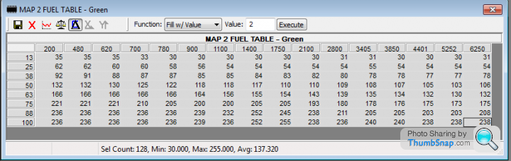
This is a portion of a Log from Sunday, the areas of interest are highlighted in Red...
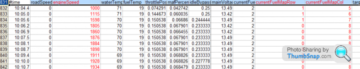
Note; when you look at the LOG RPM(Engine Speed) and the LOG currentFuelMapCol
it is not the correct column number as shown in the TunerPro image.
Count the columns from the left on TunerPro image and the RPM range doesn't match that in the RoverGauge LOG... It seems to be one step out unless we count the first Column as 0 in TunerPro.
Maybe there is something I'm not seeing.
Current Map being used (extended RPM to 6250):-
This is a portion of a Log from Sunday, the areas of interest are highlighted in Red...
Note; when you look at the LOG RPM(Engine Speed) and the LOG currentFuelMapCol
it is not the correct column number as shown in the TunerPro image.
Count the columns from the left on TunerPro image and the RPM range doesn't match that in the RoverGauge LOG... It seems to be one step out unless we count the first Column as 0 in TunerPro.
Maybe there is something I'm not seeing.
Gassing Station | Griffith | Top of Page | What's New | My Stuff