Griff chassis diagram
Discussion


I've forwarded this to one of our MCAD chaps who use SolidEdge, he has a file translator so is going to have a look see if it has this format...hmmm no joy.
Looks like you need a tool to translate from the point cloud from the scan into solid model before you can save it in a solid model format that can be imported.
bottoms There is more stuff on the web if you search...
Looks like you need a tool to translate from the point cloud from the scan into solid model before you can save it in a solid model format that can be imported.
bottoms There is more stuff on the web if you search...
Edited by Rob_the_Sparky on Thursday 10th March 13:43
Edited by Rob_the_Sparky on Thursday 10th March 13:56
Rob_the_Sparky said:
I've forwarded this to one of our MCAD chaps who use SolidEdge, he has a file translator so is going to have a look see if it has this format...hmmm no joy.
Looks like you need a tool to translate from the point cloud from the scan into solid model before you can save it in a solid model format that can be imported.
Correct you need to decimate the point cloud into something more manageable as I have done and then put it through a surfacing application. I'm getting odd results with the meshing at the moment but will persevereLooks like you need a tool to translate from the point cloud from the scan into solid model before you can save it in a solid model format that can be imported.
This is good stuff - If the point cloud scan is available in .xyx or e57 file format (or if you can check it can be saved as such from the original scanners/scan file) - I can import it into my architectural software and use as a trace base for the start of a useable model. Modelling the frame with this as a base should be relatively straightforward.
Storm Guy said:
This is good stuff - If the point cloud scan is available in .xyx or e57 file format (or if you can check it can be saved as such from the original scanners/scan file) - I can import it into my architectural software and use as a trace base for the start of a useable model. Modelling the frame with this as a base should be relatively straightforward.
I can send you the scan (full fat or my reduced one) in either format if you want to have a go at that.Send me a PM with your email address and I'll send it via MBF.
Guys, this is great, I wish I could contribute more but 3D CAD modelling is not my area of expertise. Where I can help is copious photos of a clean, blasted chassis plus any dimensions you may require as a check. I guess the deliverable here is an accurate 3D CAD model for anybody to use in the future for whatever purpose.
The other thing is that Pete Coffield offered to do another scan in a more controlled environment if that would help. Pete
The other thing is that Pete Coffield offered to do another scan in a more controlled environment if that would help. Pete
Edited by Pete Mac on Friday 11th March 14:11
Pete Mac said:
Guys, this is great, I wish I could contribute more but 3D CAD modelling is not my area of expertise. Where I can help is copious photos of a clean, blasted chassis plus any dimensions you may require as a check. I guess the deliverable here is an accurate 3D CAD model for anybody to use in the future for whatever purpose.
The other thing is that Pete Coffield offered to do another scan in a more controlled environment if that would help. Pete
I'd say lets see how we get on with this and then if we need another scan arrange that.The other thing is that Pete Coffield offered to do another scan in a more controlled environment if that would help. Pete
If that was necessary I'd suggest it was placed on outrigger supports, scanned and then supported elsewhere so the outriggers can be scanned seperately. Then those scans couild be merged so we could eliminate the stand more easily.
That however may not be necessary if Stormguy can use the cleaned scan I've sent him as a successful template.
Edited by V8 GRF on Friday 11th March 15:28
Thanks David - file safely received.
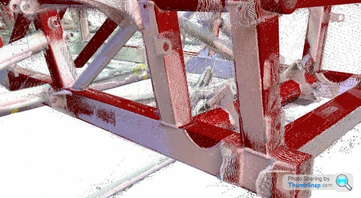
Good news folks - scan successfully imported and can be used as a ghost layer. The key however is that the scan file is not detailed enough. It's great to show the general geomtery (pics as in the other posts) - but if it is to be used an real world base (as opposed to a nice virtual model), more scan detail would be required, especially the detail that sits off the main frame, eg suspension arm connection points etc. I have lots of pics I've collected through the years of chassii - but could do with more in due course.
The file I've got has 'reduced' in the file name so am assuming it's a light version. It's also only 1.09MB - not very content heavy. As a start though the principle is good.
I'll further it a little later over the w/e and post up some pics of progress
Good news folks - scan successfully imported and can be used as a ghost layer. The key however is that the scan file is not detailed enough. It's great to show the general geomtery (pics as in the other posts) - but if it is to be used an real world base (as opposed to a nice virtual model), more scan detail would be required, especially the detail that sits off the main frame, eg suspension arm connection points etc. I have lots of pics I've collected through the years of chassii
- but could do with more in due course.The file I've got has 'reduced' in the file name so am assuming it's a light version. It's also only 1.09MB - not very content heavy. As a start though the principle is good.
I'll further it a little later over the w/e and post up some pics of progress
Gent’s I might be able to help here.
3D scanning and then reverse engineering is what I do, unfortunately I can’t get my hands on our scanners outside of work (to complex to explain) but I can take data in and process it.
I use a post processing package called PolyWorks and CATIA V5 is our CAD system.
If you can send me the scan data as you received it I should be able to process it in PolyWorks. That is take out all the noise and mesh it in an STL format and/or fit primitive features to the scan data, basic cylinders, planes, etcetera.
I can then import this lot into CATIA and re-model a clean straight and true chassis.
Don’t know how long this would take, get a better idea when I’ve seen the scan data and the work would have to done when I get time, i.e. lunch and after normal hours. Once done though it can be saved in IGES or STEP format and anybody could use it.
Cheers,
Simon.
Simon.b said:
Gent’s I might be able to help here.
3D scanning and then reverse engineering is what I do, unfortunately I can’t get my hands on our scanners outside of work (to complex to explain) but I can take data in and process it.
I use a post processing package called PolyWorks and CATIA V5 is our CAD system.
If you can send me the scan data as you received it I should be able to process it in PolyWorks. That is take out all the noise and mesh it in an STL format and/or fit primitive features to the scan data, basic cylinders, planes, etcetera.
I can then import this lot into CATIA and re-model a clean straight and true chassis.
Don’t know how long this would take, get a better idea when I’ve seen the scan data and the work would have to done when I get time, i.e. lunch and after normal hours. Once done though it can be saved in IGES or STEP format and anybody could use it.
Cheers,
Simon.
Simon, if you mail me I can send you the point cloud. Alternatively someone like V8 GRF may have taken it to another level. Peter3D scanning and then reverse engineering is what I do, unfortunately I can’t get my hands on our scanners outside of work (to complex to explain) but I can take data in and process it.
I use a post processing package called PolyWorks and CATIA V5 is our CAD system.
If you can send me the scan data as you received it I should be able to process it in PolyWorks. That is take out all the noise and mesh it in an STL format and/or fit primitive features to the scan data, basic cylinders, planes, etcetera.
I can then import this lot into CATIA and re-model a clean straight and true chassis.
Don’t know how long this would take, get a better idea when I’ve seen the scan data and the work would have to done when I get time, i.e. lunch and after normal hours. Once done though it can be saved in IGES or STEP format and anybody could use it.
Cheers,
Simon.
Larger file much better - thanks. Lost of noise to work through however.
The ghost (scan) is being used a guide to align the new structural elements and good for starters. Just looked very crudely at the basic geometry - will try and sort junctions later. It is going to take some time to sort out the finer details, but principle looks like it will work. Sounds like Simon has the right software and background to take this further.
I'll progress regardless and post up in due course.
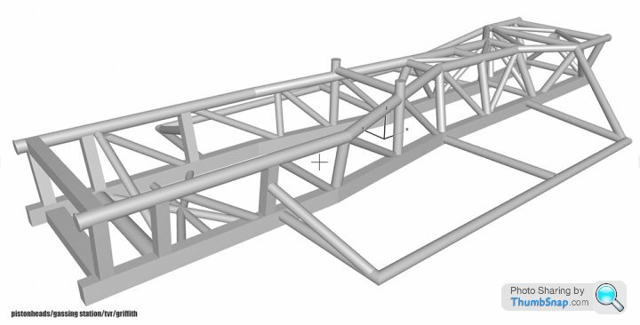
As expected, the chassis is not uniform even with geometry that you'd think should ideally be symmetrical - no doubt understandable from a hand built/welded assembly. Several mms between identical components along the longitudinal axis. Will hopefully end up with a clean geometrical model (and no doubt the frame, even given its deviations from geomtery will have enough tolerance to be of some practical use).


The ghost (scan) is being used a guide to align the new structural elements and good for starters. Just looked very crudely at the basic geometry - will try and sort junctions later. It is going to take some time to sort out the finer details, but principle looks like it will work. Sounds like Simon has the right software and background to take this further.
I'll progress regardless and post up in due course.
As expected, the chassis is not uniform even with geometry that you'd think should ideally be symmetrical - no doubt understandable from a hand built/welded assembly. Several mms between identical components along the longitudinal axis. Will hopefully end up with a clean geometrical model (and no doubt the frame, even given its deviations from geomtery will have enough tolerance to be of some practical use).
Edited by Storm Guy on Sunday 13th March 12:01
Superb stuff you're obviously a skilled CAD operator.
You really shouldn't be sutprised about the chassis not being symmetrical. As you say it was handmade and will vary depending on the skill of the welder.
I also understand that sometimes that they warped under the heat of the process so much that they had to take a mallet to them to free them from the jig.....
Storm Guy said:
Larger file much better - thanks. Lost of noise to work through however.
The ghost (scan) is being used a guide to align the new structural elements and good for starters. Just looked very crudely at the basic geometry - will try and sort junctions later. It is going to take some time to sort out the finer details, but principle looks like it will work. Sounds like Simon has the right software and background to take this further.
I'll progress regardless and post up in due course.
As expected, the chassis is not uniform even with geometry that you'd think should ideally be symmetrical - no doubt understandable from a hand built/welded assembly. Several mms between identical components along the longitudinal axis. Will hopefully end up with a clean geometrical model (and no doubt the frame, even given its deviations from geomtery will have enough tolerance to be of some practical use).
Asaad, that's spectacular, you've even managed to capture the brackets. It really doesn't surprise me that the chassis is a few mm out of symmetrical. I have looked very closely at it and I cannot spot any accident damage. As David says it probably had a fair amount of welly with a large hammer at some point in its fabrication and I question whether TVR where that diligent in the production of their chassis. I have sent the original scan to Simon b. but I don't know what software he has that does a better job than yours. In fact I am not sure who the person is who says this is a finished job.The ghost (scan) is being used a guide to align the new structural elements and good for starters. Just looked very crudely at the basic geometry - will try and sort junctions later. It is going to take some time to sort out the finer details, but principle looks like it will work. Sounds like Simon has the right software and background to take this further.
I'll progress regardless and post up in due course.
As expected, the chassis is not uniform even with geometry that you'd think should ideally be symmetrical - no doubt understandable from a hand built/welded assembly. Several mms between identical components along the longitudinal axis. Will hopefully end up with a clean geometrical model (and no doubt the frame, even given its deviations from geomtery will have enough tolerance to be of some practical use).
Edited by Storm Guy on Sunday 13th March 12:01
I guess if the chassis is only 'several' mm out from symmetrical it may be worth producing a CAD drawing that is actually symmetrical....!
Once everyone is satisfied that no further scans will add any value then this chassis is off to be galvanised and powder coated (possibly) and will form the basis of my 'nut and bolt' rebuild.
Pete
Edited by Pete Mac on Sunday 13th March 18:20
Thanks Simon.
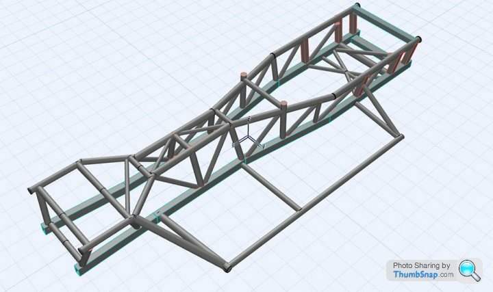
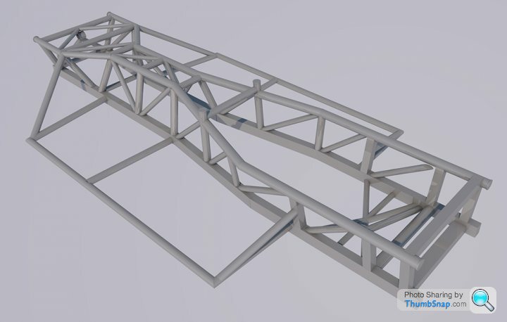
Ok folks - still in very much in draft but think it's getting there - detail to add, brackets/fixings etc.
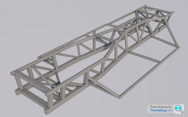
I have modelled as per scan, correcting symmetry along long axis. As stated there is quite a bit of variation between sides. Also key item is the bowing of the bottom frame along its length. Don't know whether this is intentional or age related with a slight bow. Slight kick up at the rear is normal, but also at the front end - would have thought horizontal along it's lenth bar the rear.
Nevertheless this particulalr model is as per scan, but can assess further once the weather gets better and I can get under the car to see what's mine like - and amend as needed.

Ok folks - still in very much in draft but think it's getting there - detail to add, brackets/fixings etc.
I have modelled as per scan, correcting symmetry along long axis. As stated there is quite a bit of variation between sides. Also key item is the bowing of the bottom frame along its length. Don't know whether this is intentional or age related with a slight bow. Slight kick up at the rear is normal, but also at the front end - would have thought horizontal along it's lenth bar the rear.
Nevertheless this particulalr model is as per scan, but can assess further once the weather gets better and I can get under the car to see what's mine like - and amend as needed.
Storm Guy said:
Thanks Simon.
Ok folks - still in very much in draft but think it's getting there - detail to add, brackets/fixings etc.
I have modelled as per scan, correcting symmetry along long axis. As stated there is quite a bit of variation between sides. Also key item is the bowing of the bottom frame along its length. Don't know whether this is intentional or age related with a slight bow. Slight kick up at the rear is normal, but also at the front end - would have thought horizontal along it's lenth bar the rear.
Nevertheless this particulalr model is as per scan, but can assess further once the weather gets better and I can get under the car to see what's mine like - and amend as needed.
That is truly beautiful (beauty is in the eye of the beholder).Ok folks - still in very much in draft but think it's getting there - detail to add, brackets/fixings etc.
I have modelled as per scan, correcting symmetry along long axis. As stated there is quite a bit of variation between sides. Also key item is the bowing of the bottom frame along its length. Don't know whether this is intentional or age related with a slight bow. Slight kick up at the rear is normal, but also at the front end - would have thought horizontal along it's lenth bar the rear.
Nevertheless this particulalr model is as per scan, but can assess further once the weather gets better and I can get under the car to see what's mine like - and amend as needed.
This wasn't why I started this but how far out is my chassis from symmetrical?
So all the dire warnings of my chassis warping when I get it galvanised are probably unfounded as it is already out of symmetrical.
Asaad, if I can help by doing some photos of any details on the chassis to explain anything then let me know.
Pete
Gassing Station | Griffith | Top of Page | What's New | My Stuff