Griff chassis diagram
Discussion


Hi Peter thanks. The chassis seems to have a slight kick up at the front area (appx 25mm). The rear seems to normally be about 35mm from bottom of the chassis line (horizontal) to the kick up (again measured to the bottom of the chassis member). Not sure whether the fcatory frame sat completely level along all of it's length other than the rear, or both front and rear had a kick up.
I'll email you the some model images to illustrate what I found. There is about 5mm difference between the two sides here and there, some members may be 10mm out but these are mainly cross supports so not affecting body etc. There also seems to be about 5-10mm horizontal difference between outriggers (the main side memebrs rather than the bracing back to the main frame). Of course every mm will become obvious when CAD modelling but in reality doubt if any of this would make a significant difference other than in the obvious critical areas.
What may help (Pete or anyone else who has their body off) is confirmation of the tube diameters and main box section sizes - I have concentrated first on getting the geometry right for the model, just fitting tube sizes within the scan points, rather than worrying too much about accurate sizes yet. Would be good to have someone quickly mark up sizes on one of the images for clarity. Many thanks
Storm Guy said:
Hi Peter thanks. The chassis seems to have a slight kick up at the front area (appx 25mm). The rear seems to normally be about 35mm from bottom of the chassis line (horizontal) to the kick up (again measured to the bottom of the chassis member). Not sure whether the fcatory frame sat completely level along all of it's length other than the rear, or both front and rear had a kick up.
I'll email you the some model images to illustrate what I found. There is about 5mm difference between the two sides here and there, some members may be 10mm out but these are mainly cross supports so not affecting body etc. There also seems to be about 5-10mm horizontal difference between outriggers (the main side memebrs rather than the bracing back to the main frame). Of course every mm will become obvious when CAD modelling but in reality doubt if any of this would make a significant difference other than in the obvious critical areas.
What may help (Pete or anyone else who has their body off) is confirmation of the tube diameters and main box section sizes - I have concentrated first on getting the geometry right for the model, just fitting tube sizes within the scan points, rather than worrying too much about accurate sizes yet. Would be good to have someone quickly mark up sizes on one of the images for clarity. Many thanks
AsaadI'll email you the some model images to illustrate what I found. There is about 5mm difference between the two sides here and there, some members may be 10mm out but these are mainly cross supports so not affecting body etc. There also seems to be about 5-10mm horizontal difference between outriggers (the main side memebrs rather than the bracing back to the main frame). Of course every mm will become obvious when CAD modelling but in reality doubt if any of this would make a significant difference other than in the obvious critical areas.
What may help (Pete or anyone else who has their body off) is confirmation of the tube diameters and main box section sizes - I have concentrated first on getting the geometry right for the model, just fitting tube sizes within the scan points, rather than worrying too much about accurate sizes yet. Would be good to have someone quickly mark up sizes on one of the images for clarity. Many thanks
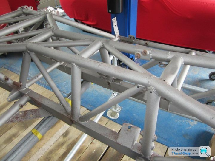
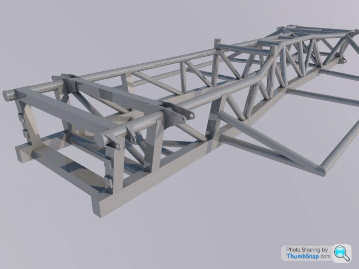
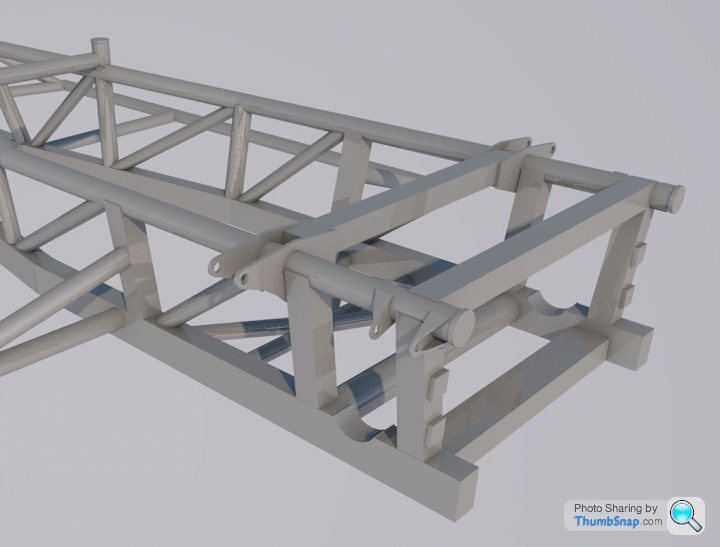
I have gone round and measured the various tubes and box sections:
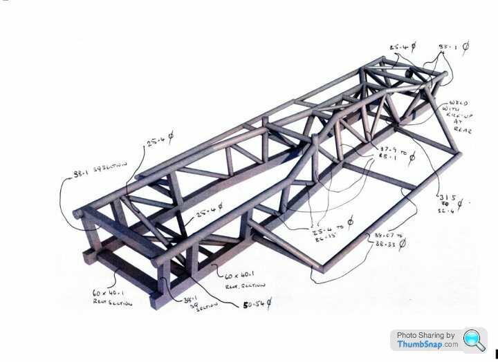
I hope this is clear. The measurements are there or there abouts given the chassis has had a fairly harsh media blast and has been subject to TVR engineering!
Chassis seems to be made up of 60mmx40mm box section, 38mm square section, 25.4mm tube, 38mm tube and there is a 50.5mm tube cross piece at the front.
There is definitely a kick up at the rear, there is a weld and there is also a weld at the front. The kick up is not so pronounced. Symmetry I am not too bothered about as I guess that is TVR for you more than distortion.
The following are photos of the complicated sections for your reference. I think one of them more or less shows the kick up.
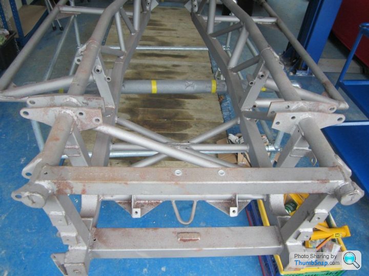

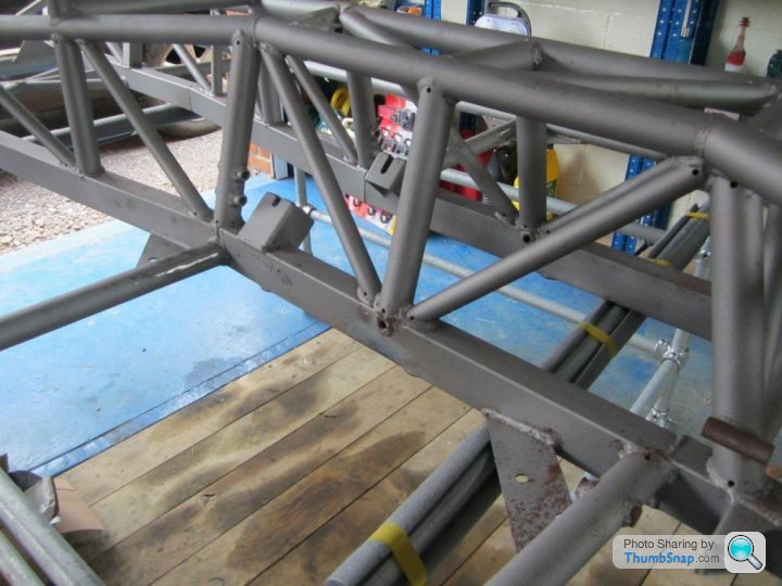
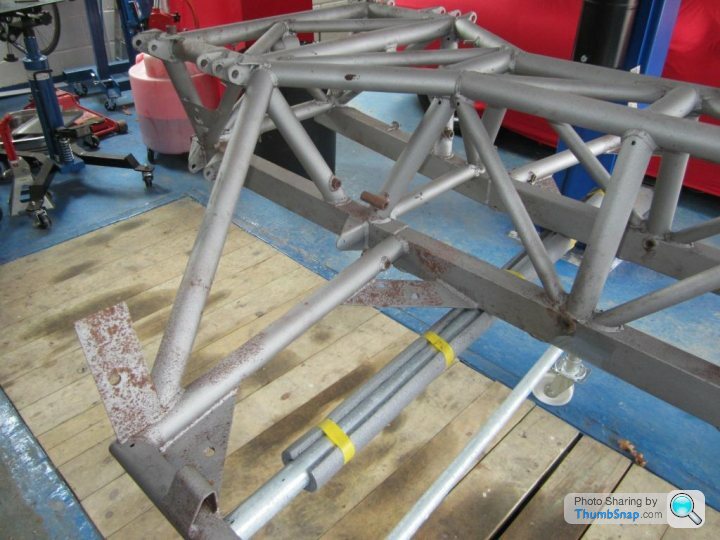
I hope this is helpful. Pete
Storm Guy said:
That is great Pete, very helpful and just the job - many thanks.
The model is getting there but having to fit it in as and when - a few brackets added with general sizes amended a per your dims annotation.
Asaad, that is really very clever. It looks like you really know your stuff.The model is getting there but having to fit it in as and when - a few brackets added with general sizes amended a per your dims annotation.
I am, unfortunately sitting in Moscow Airport on my way back to work in Kazakhstan so won't have acess to chassis for 4 weeks. I will have it galvanised on my return.
I will follow this thread with interest. Pete
 Superb stuff.
FlipFlopGriff said:
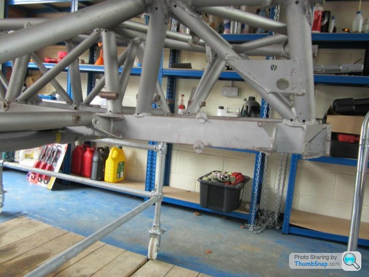
Is that why there are holes in all the tubes? Not standard I assume?
FFG
Correct. 2 x 5mm holes as close to the welds as possible, one hole to vent and the other to drain the molten zinc. I think the galvanisers may insist I open up the holes in the big members to 8mm but I will see what I can get away with. Will report back when I finally do it. PeteFFG
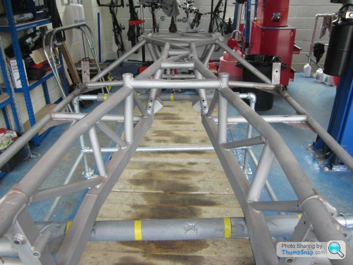
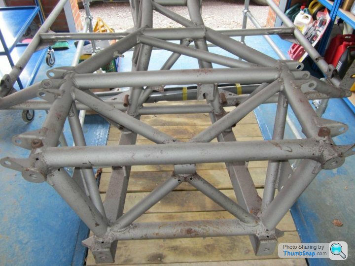
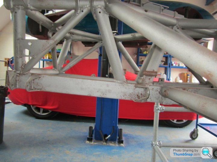
Is it just me or is one of the diagonals at what I guess to be the back of the engine bay is vertical on one side but 45 degrees on the other? At work so can't take a look at my car but looks too different to be to be a mistake. Something to do with accommodating the steering or starter motor??
Rob_the_Sparky said:
Is it just me or is one of the diagonals at what I guess to be the back of the engine bay is vertical on one side but 45 degrees on the other? At work so can't take a look at my car but looks too different to be to be a mistake. Something to do with accommodating the steering or starter motor??
It's not an error but you're correct, the bracing does differ from one side to the other with a long length on the offside (drivers)followed by a short section with the reverse on the nearside (passenger)As you said it's probably a clearance issue or maybe adding some different angles in to aid stiffness.
Storm Guy said:
Thank you 
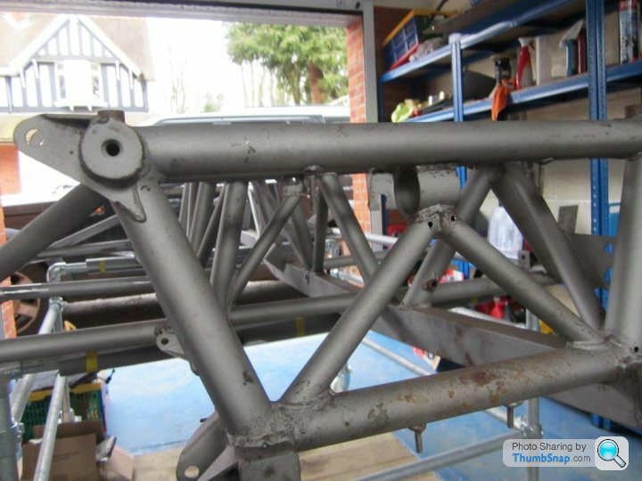
Good point Pete - must say, I'd missed that bit. Yes the scan shows it. I also need to do the squished bits to the rear side of penultimate front two vertical members.
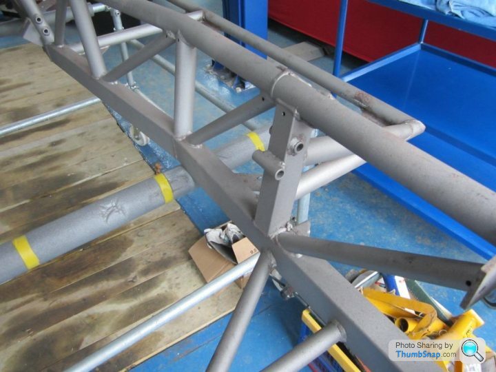
This I presume you mean?Good point Pete - must say, I'd missed that bit. Yes the scan shows it. I also need to do the squished bits to the rear side of penultimate front two vertical members.
A lovely bit of engineering I must say. Do you think they used a 10lb lumb hammer and blunt cold chisel? Don't we just love TVRs.
I can't remember what these are for, presumably something on the engine...?
Pete
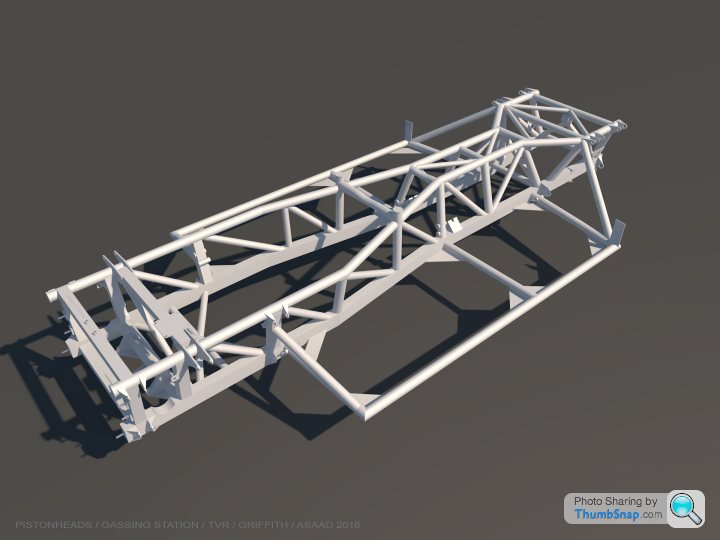
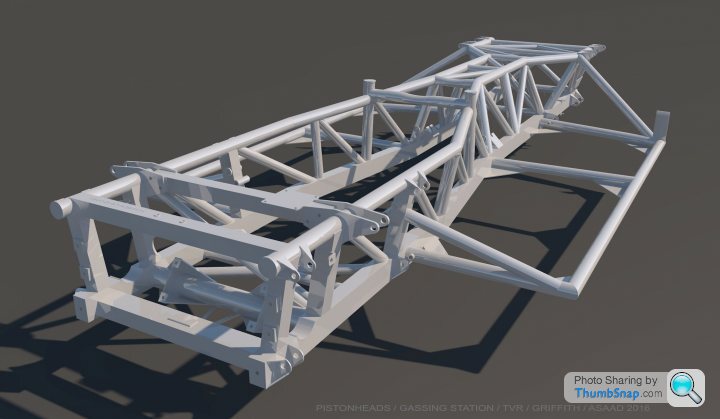
Here it is folks....
This has taken some considerable time and effort to get sorted but hope it is of some use.
Needed to get it off my plate as I have some other pressing commitments ahead – but wanted to get it to a certain stage.
As you know it started out as a check to see if a point cloud scan could reasonably be used as a starting point for a CAD model.
Some of my earlier queries / confusion re angles, kick ups etc was from the fact that (and no criticism of the scan, as it was the ideal starting point) - the chassis seems to have been ever so slightly off horizontal when scanned. This could have been for several reasons including that the scaffold frame it sat on may have been mms off level.
This only became apparent after researching more and more chassis information /pictures etc. As I was originally using the scan as a base, the resulting model angles were all a little slightly off - so decided to redo the model with the principles of a level base and true geometry/symmetry (to cater for any age related bowing/distortion etc) etc. This impacted on all the already modelled angles as you can imagine.
Unfortunately I could not rotate either scan, nor the individual elements in one go - though I actually think this may have led to more issues that it would have solved.
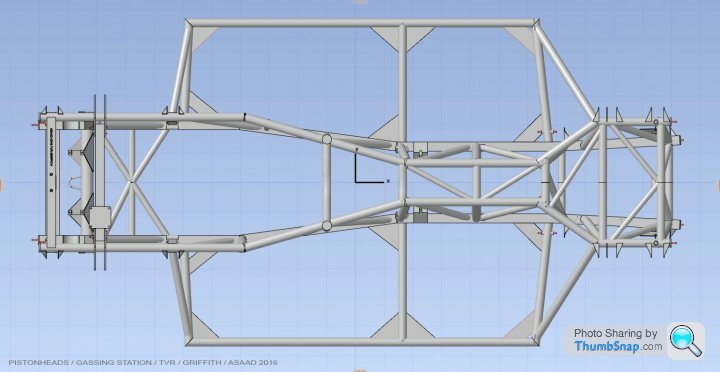
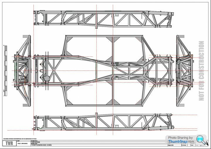
Please find below a link to the 1:5 scale pdf chassis drawing plans/elevations. Though they are to scale but have as yet no dimensions – with obviously a clear note added that these are intended purely for information and not for construction. Whereas it is a fairly accurate representation, based on the scan, and then adjusted to form a ‘true’ chassis, it can only ever be diagrammatic.
Linear dims / angles could in theory be added (along with frame member diameters/box sizes as per Pete’s info), but you can see the potential issues due to my interpretation.
Please also a link to the viewer (Graphisoft’s BIMx viewer) for the 3D CAD model.
It is available as a free download for the IPad or as a desktop PC viewer (which has more user settings than the mobile version) – search BIMx on the AppStore, or for desktop go to here….
http://www.graphisoft.com/downloads/bimx/bimx_desk...
Please download the instructions (BIMx Quick Reference Card) to understand the navigation and settings, although very easy to use (mouse and keyboard arrows on desktop, finger / touch surface on iPad) -some good tools in settings.
CAD Model and PDF downloadable here:……http://bit.ly/1Spe0xM
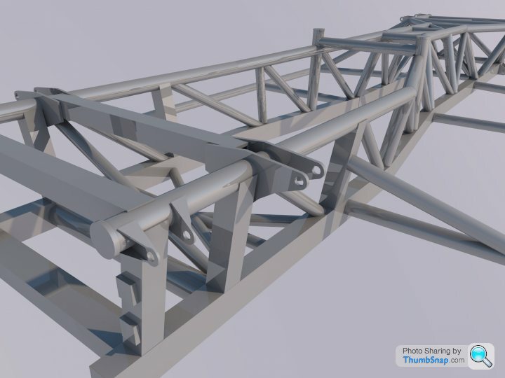
Actual model views that you will be able to navigate...
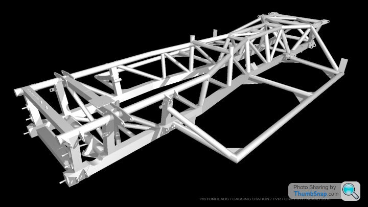
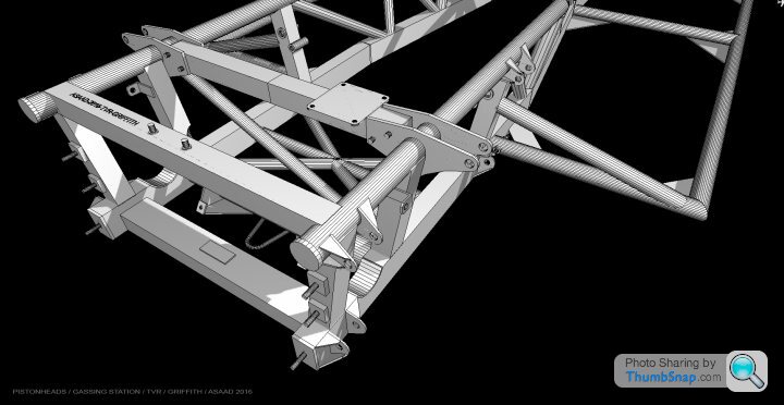
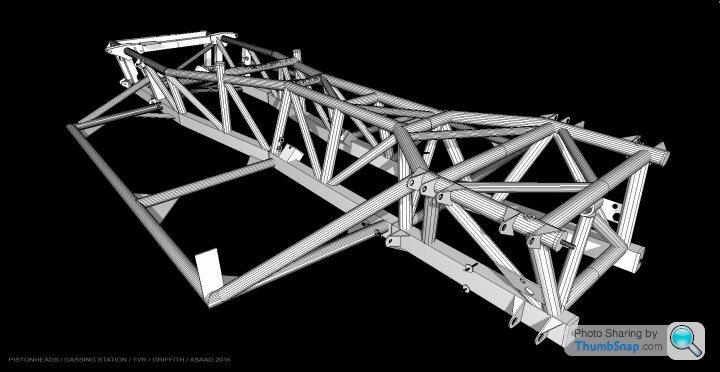
The model will evolve (and be fine tuned) over time - modelling brake line routings, suspension arms, ARB, fixings and the like.
Will share updates of the 3D model as it develops, but now may not be for some time.
For the TVR community, I hope it serves some purpose (and of course, thanks to Pete and David for sparking me into something I may wish I never started ).
Notwithstanding the effort gone into the modelling, the standard disclaimer ‘for info only’ – but primarily the commercial benefit that some may gain from it - think it best not to share or release the master CAD model file (or formats thereof) other than the BIMx file above. Am sure you good folk will appreciate the reasoning.
Any issues viewing, or with the modelling, please do let me know and hope it helps – has certainly been interesting. Thanks.
This has taken some considerable time and effort to get sorted but hope it is of some use.
Needed to get it off my plate as I have some other pressing commitments ahead – but wanted to get it to a certain stage.
As you know it started out as a check to see if a point cloud scan could reasonably be used as a starting point for a CAD model.
Some of my earlier queries / confusion re angles, kick ups etc was from the fact that (and no criticism of the scan, as it was the ideal starting point) - the chassis seems to have been ever so slightly off horizontal when scanned. This could have been for several reasons including that the scaffold frame it sat on may have been mms off level.
This only became apparent after researching more and more chassis information /pictures etc. As I was originally using the scan as a base, the resulting model angles were all a little slightly off - so decided to redo the model with the principles of a level base and true geometry/symmetry (to cater for any age related bowing/distortion etc) etc. This impacted on all the already modelled angles as you can imagine.
Unfortunately I could not rotate either scan, nor the individual elements in one go - though I actually think this may have led to more issues that it would have solved.
Please find below a link to the 1:5 scale pdf chassis drawing plans/elevations. Though they are to scale but have as yet no dimensions – with obviously a clear note added that these are intended purely for information and not for construction. Whereas it is a fairly accurate representation, based on the scan, and then adjusted to form a ‘true’ chassis, it can only ever be diagrammatic.
Linear dims / angles could in theory be added (along with frame member diameters/box sizes as per Pete’s info), but you can see the potential issues due to my interpretation.
Please also a link to the viewer (Graphisoft’s BIMx viewer) for the 3D CAD model.
It is available as a free download for the IPad or as a desktop PC viewer (which has more user settings than the mobile version) – search BIMx on the AppStore, or for desktop go to here….
http://www.graphisoft.com/downloads/bimx/bimx_desk...
Please download the instructions (BIMx Quick Reference Card) to understand the navigation and settings, although very easy to use (mouse and keyboard arrows on desktop, finger / touch surface on iPad) -some good tools in settings.
CAD Model and PDF downloadable here:……http://bit.ly/1Spe0xM
Actual model views that you will be able to navigate...
The model will evolve (and be fine tuned) over time - modelling brake line routings, suspension arms, ARB, fixings and the like.
Will share updates of the 3D model as it develops, but now may not be for some time.
For the TVR community, I hope it serves some purpose (and of course, thanks to Pete and David for sparking me into something I may wish I never started ).
Notwithstanding the effort gone into the modelling, the standard disclaimer ‘for info only’ – but primarily the commercial benefit that some may gain from it - think it best not to share or release the master CAD model file (or formats thereof) other than the BIMx file above. Am sure you good folk will appreciate the reasoning.
Any issues viewing, or with the modelling, please do let me know and hope it helps – has certainly been interesting. Thanks.
Edited by Storm Guy on Wednesday 19th October 16:51

Storm Guy said:
Here it is folks....
This has taken some considerable time and effort to get sorted but hope it is of some use.
Needed to get it off my plate as I have some other pressing commitments ahead – but wanted to get it to a certain stage.
As you know it started out as a check to see if a point cloud scan could reasonably be used as a starting point for a CAD model.
Some of my earlier queries / confusion re angles, kick ups etc was from the fact that (and no criticism of the scan, as it was the ideal starting point) - the chassis seems to have been ever so slightly off horizontal when scanned. This could have been for several reasons including that the scaffold frame it sat on may have been mms off level.
This only became apparent after researching more and more chassis information /pictures etc. As I was originally using the scan as a base, the resulting model angles were all a little slightly off - so decided to redo the model with the principles of a level base and true geometry/symmetry (to cater for any age related bowing/distortion etc) etc. This impacted on all the already modelled angles as you can imagine.
Unfortunately I could not rotate either scan, nor the individual elements in one go - though I actually think this may have led to more issues that it would have solved.
Please find below a link to the 1:5 scale pdf chassis drawing plans/elevations. Though they are to scale but have as yet no dimensions – with obviously a clear note added that these are intended purely for information and not for construction. Whereas it is a fairly accurate representation, based on the scan, and then adjusted to form a ‘true’ chassis, it can only ever be diagrammatic.
Linear dims / angles could in theory be added (along with frame member diameters/box sizes as per Pete’s info), but you can see the potential issues due to my interpretation.
Please also a link to the viewer (Graphisoft’s BIMx viewer) for the 3D CAD model.
It is available as a free download for the IPad or as a desktop PC viewer (which has more user settings than the mobile version) – search BIMx on the AppStore, or for desktop go to here….
http://www.graphisoft.com/downloads/bimx/bimx_desk...
Please download the instructions (BIMx Quick Reference Card) to understand the navigation and settings, although very easy to use (mouse and keyboard arrows on desktop, finger / touch surface on iPad) -some good tools in settings.
CAD Model and PDF downloadable here:……http://bit.ly/1Spe0xM
Actual model views that you will be able to navigate...
The model will evolve (and be fine tuned) over time - modelling brake line routings, suspension arms, ARB, fixings and the like.
Will share updates of the 3D model as it develops, but now may not be for some time.
For the TVR community, I hope it serves some purpose (and of course, thanks to Pete and David for sparking me into something I may wish I never started ).
Notwithstanding the effort gone into the modelling, the standard disclaimer ‘for info only’ – but primarily the commercial benefit that some may gain from it - think it best not to share or release the master CAD model file (or formats thereof) other than the BIMx file above. Am sure you good folk will appreciate the reasoning.
Any issues viewing, or with the modelling, please do let me know and hope it helps – has certainly been interesting. Thanks.
Asaad, This has taken some considerable time and effort to get sorted but hope it is of some use.
Needed to get it off my plate as I have some other pressing commitments ahead – but wanted to get it to a certain stage.
As you know it started out as a check to see if a point cloud scan could reasonably be used as a starting point for a CAD model.
Some of my earlier queries / confusion re angles, kick ups etc was from the fact that (and no criticism of the scan, as it was the ideal starting point) - the chassis seems to have been ever so slightly off horizontal when scanned. This could have been for several reasons including that the scaffold frame it sat on may have been mms off level.
This only became apparent after researching more and more chassis information /pictures etc. As I was originally using the scan as a base, the resulting model angles were all a little slightly off - so decided to redo the model with the principles of a level base and true geometry/symmetry (to cater for any age related bowing/distortion etc) etc. This impacted on all the already modelled angles as you can imagine.
Unfortunately I could not rotate either scan, nor the individual elements in one go - though I actually think this may have led to more issues that it would have solved.
Please find below a link to the 1:5 scale pdf chassis drawing plans/elevations. Though they are to scale but have as yet no dimensions – with obviously a clear note added that these are intended purely for information and not for construction. Whereas it is a fairly accurate representation, based on the scan, and then adjusted to form a ‘true’ chassis, it can only ever be diagrammatic.
Linear dims / angles could in theory be added (along with frame member diameters/box sizes as per Pete’s info), but you can see the potential issues due to my interpretation.
Please also a link to the viewer (Graphisoft’s BIMx viewer) for the 3D CAD model.
It is available as a free download for the IPad or as a desktop PC viewer (which has more user settings than the mobile version) – search BIMx on the AppStore, or for desktop go to here….
http://www.graphisoft.com/downloads/bimx/bimx_desk...
Please download the instructions (BIMx Quick Reference Card) to understand the navigation and settings, although very easy to use (mouse and keyboard arrows on desktop, finger / touch surface on iPad) -some good tools in settings.
CAD Model and PDF downloadable here:……http://bit.ly/1Spe0xM
Actual model views that you will be able to navigate...
The model will evolve (and be fine tuned) over time - modelling brake line routings, suspension arms, ARB, fixings and the like.
Will share updates of the 3D model as it develops, but now may not be for some time.
For the TVR community, I hope it serves some purpose (and of course, thanks to Pete and David for sparking me into something I may wish I never started ).
Notwithstanding the effort gone into the modelling, the standard disclaimer ‘for info only’ – but primarily the commercial benefit that some may gain from it - think it best not to share or release the master CAD model file (or formats thereof) other than the BIMx file above. Am sure you good folk will appreciate the reasoning.
Any issues viewing, or with the modelling, please do let me know and hope it helps – has certainly been interesting. Thanks.
Absolutely superb stuff, a real masterpiece.
The scaffold frame that I made is almost certainly off horizontal and it was perched on the wooden hatch above my mancave, so although stable the whole structure was off horizontal. We made no attempt to level the chassis. A lessons learnt for me if I ever attempted to do something like this again - set a level datum point. As I said before, I never realised the effort required to turn a scan into a 3D CAD drawing.
I would also like to thank Pete Coffield who did the scan, it took him the best part of a day to do this. He doesn't scan car bits for a business, this was just a bit of fun so we had his time and use of his scanning equipment for nothing - thanks Pete.
Although I understand your 'health warnings' over the use of these drawings it seems a pity that this thread just disappears down the Pistonheads list on the Griffith Forum. I think this is at least worth an article in the Sprint Magazine, taking people through the process. What do you think? Pete
Pete Mac said:
<snip>
Although I understand your 'health warnings' over the use of these drawings it seems a pity that this thread just disappears down the Pistonheads list on the Griffith Forum. I think this is at least worth an article in the Sprint Magazine, taking people through the process. What do you think? Pete
Hi Pete, yes I was thinking about an article. So if you'd like to compile the first elements up to posting here I think Stormguy and I can add our parts as well.Although I understand your 'health warnings' over the use of these drawings it seems a pity that this thread just disappears down the Pistonheads list on the Griffith Forum. I think this is at least worth an article in the Sprint Magazine, taking people through the process. What do you think? Pete
You could ask teh PH mods to pin this so it doesn't 'sink'
Gassing Station | Griffith | Top of Page | What's New | My Stuff