280i fuel hoses
Discussion


Hi guys, inspired by Zigs cooling hose diagram, I've done one of my fuel hoses.. Hoping someone can shed some light on a question I have.
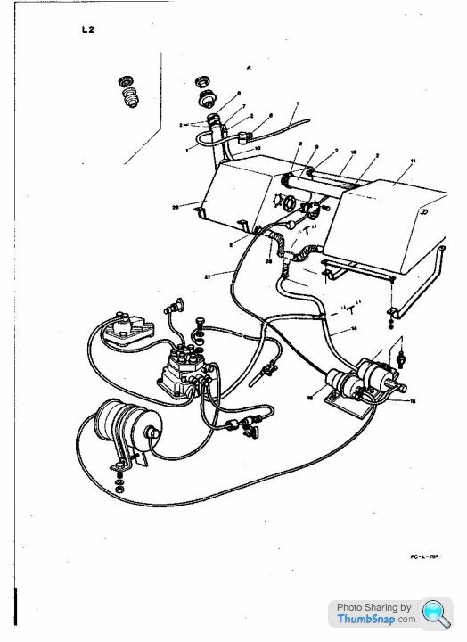
I need to know how to connect up the 4 numbered pipes. They are all the same size, but when I pulled the car apart, only 1. and 4 existed, and were connected, i.e. the fuel return went back into the nearside tank.
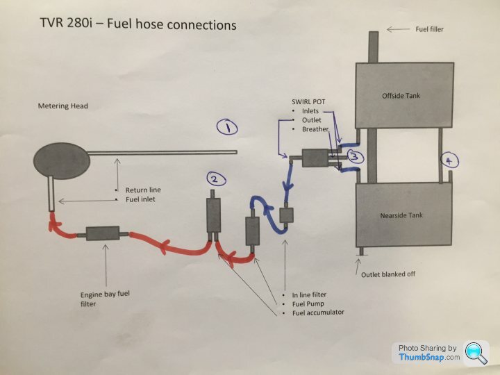
However.... I now have a brand new swirl pot (3) and a brand new fuel accumulator (2). BOTH have an extra outlet pipe compared to the "originals". Should I blank off 2 and 3 or is there a better solution?
Thanks in advance!
Toby
I need to know how to connect up the 4 numbered pipes. They are all the same size, but when I pulled the car apart, only 1. and 4 existed, and were connected, i.e. the fuel return went back into the nearside tank.
However.... I now have a brand new swirl pot (3) and a brand new fuel accumulator (2). BOTH have an extra outlet pipe compared to the "originals". Should I blank off 2 and 3 or is there a better solution?
Thanks in advance!
Toby
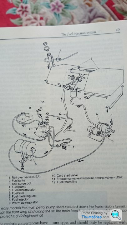
Mmmm...This was my fuel hose layout when i bought Delilah..
This was a right pigs ear...I suffered from cavitation of th pump and all sorts..
Then the "Tee's" were removed from where they were not needed....The return line from the metering unit was still "Tee'd" into the pump line and although it wasn't right i can't remember if it had any implications on the supply to the pump...
And then when i had to by-pass the accumulator...
All this time i never had an outlet to consider from the swirl pot....And the "T" was removed from the return from the metering unit and connected directly to the tank.
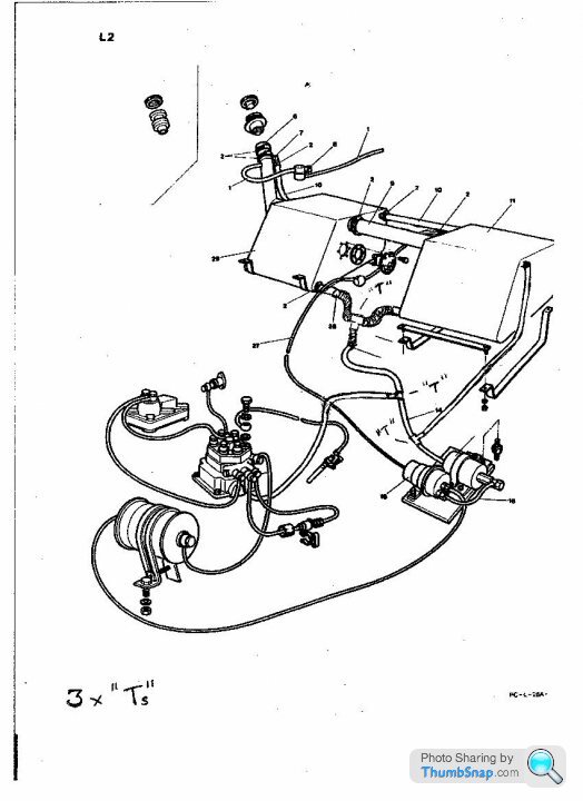
Mark,
Your 350i diagram above worries me somewhat... I really hope you haven't got an overflow pipe; I've never heard of such a thing.
What you have labelled as an overflow is actually the connection for the return line from the fuel rail; and the connection you've labelled as 'return from bulkhead' should be connected to the small vent line from the 'swirl pot'.
Quick answer is that 1,2 should link up to 4. I think 3 does too, but not sure.
1 and 2 are definitely fuel returns, and therefore go back to the main tank.
The pump should get a direct feed, so tanks to swirl pot to pump, then accumulator, then filter, then metering head.
Then all the rest are returns for overflow, pressure relief etc.
I haven't got a swirl tank in mine, just a T joiner from tanks to pump.
Thanks guys. Bit of a puzzle, this!
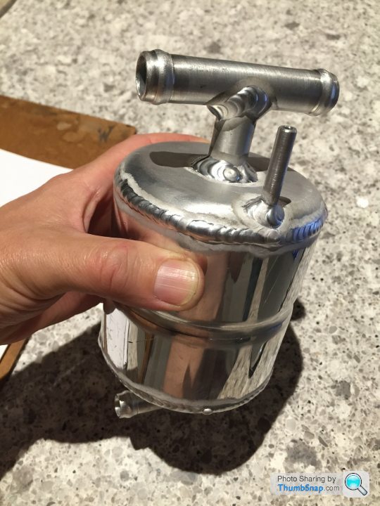
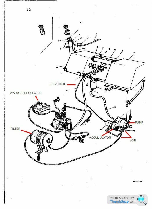
The thin outlet from the swirl pot (3) was called a "breather" by RT, and takes bubbles out of the fuel feed, so I agree it should terminate at the tank (4). Can the swirl pot also accept returned fuel from (1) (say via a T piece)? Seems counter intuitive.
But if so that would just leave (2), from the accumulator. As I understand it there is a diaphragm in there so it shouldn't have fuel coming through unless it fails. As I say, the old one had no such outlet.
Any other thoughts?
Could be Aaron. You'd think either a swirl pot breather is required or it isn't. If I blanked it off with some hose and a bung there should be no difference as it would then be like my old one which gave no trouble at all.
Heard from KMI who supplied the accumulator and fuel pump, and they say the outlet on the back is a breather (If the seal goes fuel will come out) and that some manufacturers pipe it to the tank while others leave it completely open. Don't fancy that really, but equally I don't fancy the fuel return being connected to the back of the accumulator.
How about: fuel return (1) to tank (4), blank off swirl pot and cap off the accumulator leaving a small breather hole to prevent pressure behind the diapgragm?
Personally having an air breather on a swirl pot doesn't seem practical..For a start the breather is lower than the feed so the breather would essentially be full of fuel anyway down to the volume of fuel above it....Where would the air come from?..Surely the natural gravity of the fuel passing through the swirl pot would pull air in from a breather?..There is no vacuum due to the tank breather.
Perhaps the accumulator could be plumbed into the filler neck breather..After all it is just air.
There are simply not enough outlets/Inlets to accommodate .....
Perhaps the accumulator could be plumbed into the filler neck breather..After all it is just air.
There are simply not enough outlets/Inlets to accommodate .....
I replaced all the fuel hoses from the tanks to the pump and the pump itself on my 280 last summer.
From memory (will dig out some photos this evening that I took if I can find them) I think mine was set up as follows...
Return from the engine bay was connected to the nearside tank.
'Breather'/third connection on top of the swirl pot - This connected back to the nearside tank also, on a seperate inlet.
There was no return or anything from the pump or acumulator.
I suspect the evolution of the 'swirl pot' is a classic example of TVR product development being done on customer cars. I'd have thought the later types with the breather would work the best; however judging by the cooling system evolution I'm not convinced that they know what they were doing when changing things!
PS... it's not really a swirl pot as there's no swirl involved - i think it's just a reservoir to try to prevent fuel starvation on cornering.
PS... it's not really a swirl pot as there's no swirl involved - i think it's just a reservoir to try to prevent fuel starvation on cornering.
As far as I know, some accumulators had a 'breather' which was really a safety thing, in case the unit developed a leak ?? But it doesn't quite make sense, I agree..... The accumulator is just a diaphragm and a spring....
and same for 'swirl pot' It's just an extra reservoir really, a bigger T piece.
and same for 'swirl pot' It's just an extra reservoir really, a bigger T piece.
Hi all, can anyopne tell me (or post a photo of) the route the fuel hose and return line follow from the nearside outrigger into and out of the engine bay please? do they use the hole in the top of the wheelarch and if so, is there a grommet and some protection from stones coming off the front N/S wheel? Just one more photo I didn't take before dismantling! Thanks.
I've no idea if mine is original or not, but supply pipe runs from pump along outrigger, under sill moulding, and then is clipped to chassis to get to metering unit.
Return pipe is clipped along spine of chassis then to tank on opposite side from pump.
I reckon you can put it anywhere within reason, as long as it doesn't chafe on anything.
Return pipe is clipped along spine of chassis then to tank on opposite side from pump.
I reckon you can put it anywhere within reason, as long as it doesn't chafe on anything.
Gassing Station | Wedges | Top of Page | What's New | My Stuff