Hazards work, but no indicators. Early Grifith
Discussion


From ex Auto sparks....there wont be a seperate Flasher relay....so your Hazards work fine...thats good all circuits to lamps OK...but when Hazords are off...2 contacts within The Hazard switch re - join to enable normal flashers...so there 2 fuses involved....one for Hazards...permant live....and one for normal flashers ignition only...check fuse...could be a lose connection at Flasher switch itself...best i can help . Peter
Thank you.
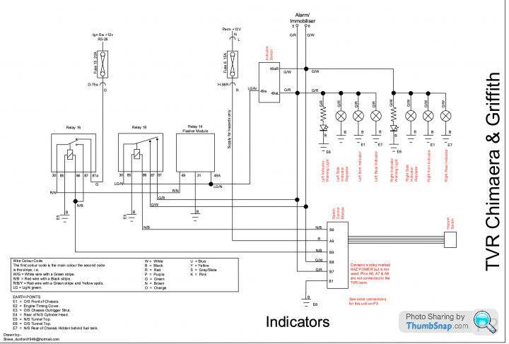
As I understand it then (according to the attached), my indicator stalk switch will have a light green/brown (LGN) ignition switched live, and then the switch makes the circuit with either the left (green/red), or right (green/white) cable. I presume these left and right cables from the switch go to the flasher relay, before going off to the bulbs?
 stalk swiot
As I understand it then (according to the attached), my indicator stalk switch will have a light green/brown (LGN) ignition switched live, and then the switch makes the circuit with either the left (green/red), or right (green/white) cable. I presume these left and right cables from the switch go to the flasher relay, before going off to the bulbs?
stalk swiotIf you see numbers on the Hazard switch...some dont have im affraid...but No 15 will be live with the Ignition on....OK....No 30 will be live all the time.....OK.....No 49 will come live when Hazards off ONLY...thats where the switching of circuits takes place.....Hazards take place when turned on linking then with No 30.....then sending all indicators working [ ie GW...& GR ].....as said make sure you have live 15 [ fused ]....i feel you have disturbed something when dash out...as guess all OK before...sorry cant help more...Peter now 81 years.
Peter-jforf said:
If you see numbers on the Hazard switch...some dont have im affraid...but No 15 will be live with the Ignition on....OK....No 30 will be live all the time.....OK.....No 49 will come live when Hazards off ONLY...thats where the switching of circuits takes place.....Hazards take place when turned on linking then with No 30.....then sending all indicators working [ ie GW...& GR ].....as said make sure you have live 15 [ fused ]....i feel you have disturbed something when dash out...as guess all OK before...sorry cant help more...Peter now 81 years.
Ah so it's all done at the hazard switch, I see. That will help greatly; thanks for the detail. You've still got it at 81 years. :-)
Well yes, I had the dash out completely for repairing, so I've disconnected and reconnected a lot of stuff back there.
Belle427 said:
Not sure if this helps too.
https://www.pistonheads.com/gassing/topic.asp?h=0&...
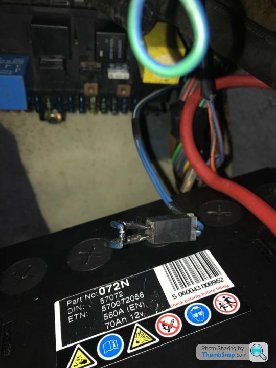
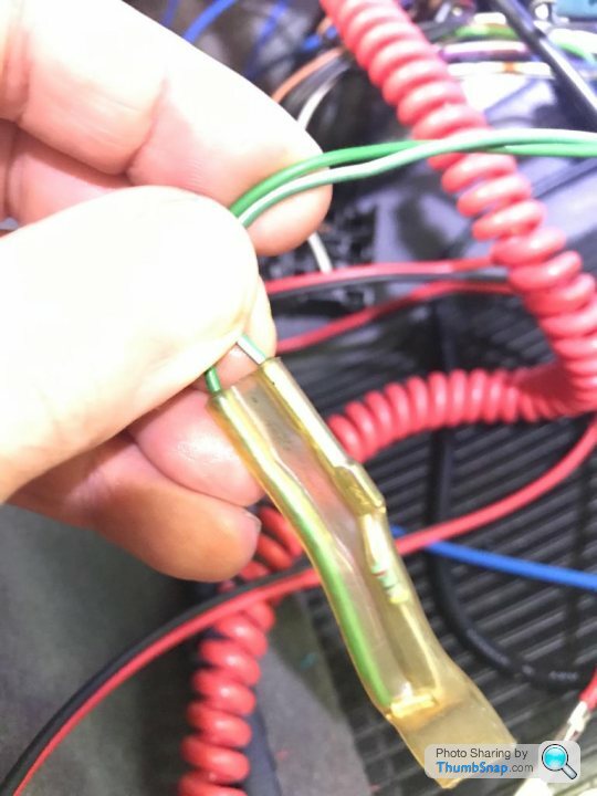
Certainly does, thanks; I think I might have seen this diode in the snakes' wedding in the footwell.https://www.pistonheads.com/gassing/topic.asp?h=0&...
I got some extremely useful, and 1000 times easier to read, electrical diagrams from Steve D on here.
It covers lots of areas including the indicators.
PM me, and I'll email the bundle, the resolution is perfect as a pdf, terrible on this forum.
It covers lots of areas including the indicators.
PM me, and I'll email the bundle, the resolution is perfect as a pdf, terrible on this forum.
Edited by PabloGee on Friday 5th January 14:28
Re the above diagram....all OK......if your car is same....then 49A is the important circuit that may be not there at normal indicator switch....LG/N.....again i mention may be a Fuse gone on ignition....as i see your car if ?? with that diagram all OK as Hazards work fine.....over complicated early system i guess..... Peter
PabloGee said:
I got some extremely useful, and 1000 times easier to read, electrical diagrams from Steve D on here.
It covers lots of areas including the indicators.
PM me, and I'll email the bundle, the resolution is perfect as a pdf, terrible on this forum.
Wow, what an improvement! Have sent you an email for those diagrams. Thanks.It covers lots of areas including the indicators.
PM me, and I'll email the bundle, the resolution is perfect as a pdf, terrible on this forum.
Edited by PabloGee on Friday 5th January 14:28
So I've got no switched live on wire LG/N at the indicator switch.
I have found what I think are the relays (top 2 in first photo), since they do indeed have the G/R and G/W wires going to them, but they do not match the diagram.
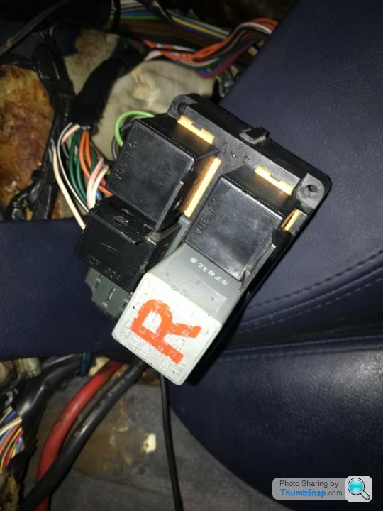
My G/R and G/W indicator wires go to separate relays, and these relays only have 4 pins (they do not have the 5th 87a pin). My Griffith is an early '92 car, so I don't think this diagram applies.
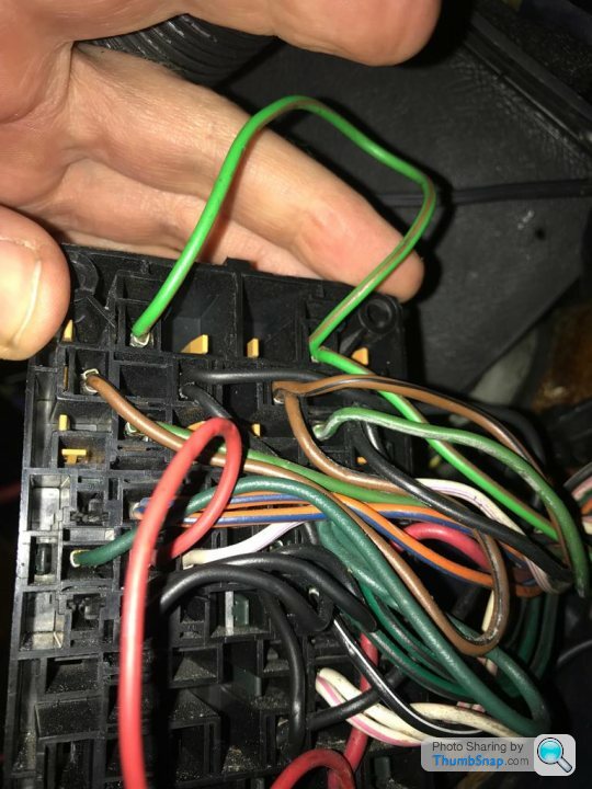
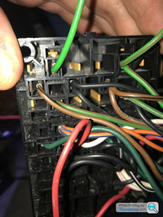
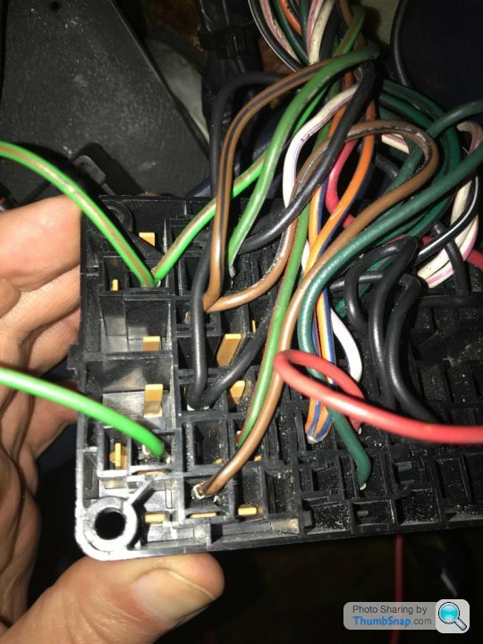
I've checked for switch live on the LG/N wire at the relays but it's dead.
I have found what I think are the relays (top 2 in first photo), since they do indeed have the G/R and G/W wires going to them, but they do not match the diagram.
My G/R and G/W indicator wires go to separate relays, and these relays only have 4 pins (they do not have the 5th 87a pin). My Griffith is an early '92 car, so I don't think this diagram applies.
I've checked for switch live on the LG/N wire at the relays but it's dead.
Should there be an ignition switched live up at the indicator switch i.e. the LG/N wire that is up at the stalk, should that become a permanent supply when ignition is on, and then operating the indicator stalk makes a connection between the live LG/N and either the G/R or G/N?
Should I expect my test lamp to find a supply at the stalk on LG/N with ignition on, even if switch is in middle neutral position?
Should I expect my test lamp to find a supply at the stalk on LG/N with ignition on, even if switch is in middle neutral position?
Gassing Station | Griffith | Top of Page | What's New | My Stuff