Hazards work, but no indicators. Early Grifith
Discussion


PreCat Griffith said:
Should there be an ignition switched live up at the indicator switch i.e. the LG/N wire that is up at the stalk, should that become a permanent supply when ignition is on, and then operating the indicator stalk makes a connection between the live LG/N and either the G/R or G/N?
Should I expect my test lamp to find a supply at the stalk on LG/N with ignition on, even if switch is in middle neutral position?
Thats how i assumed it worked, terminal 49a when connected to the load starts the flash.Should I expect my test lamp to find a supply at the stalk on LG/N with ignition on, even if switch is in middle neutral position?
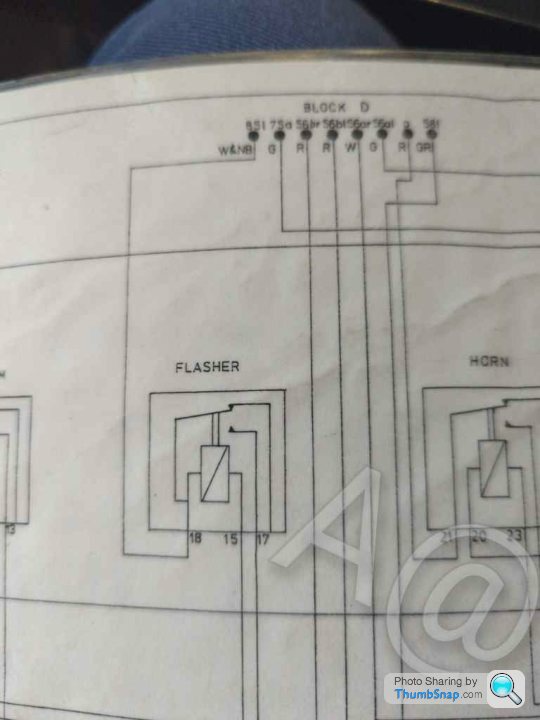
Hazards work so this suggests there is an output at 49a working ok which gets connected by relay 16 terminals 87.
Seems to suggest something amiss after the indicator switch itself but this is odd, connecting a test lamp to terminal 49a should make the flasher operate but im not 100% sure on that tbh.
You can disregard that diagram from earlier; my early Griff is wired differently. There are indeed 2 relays and a flasher, but each indicator seems to have it's own relay.
I'm focusing on the diode now and doing research of old threads on here. Thanks for planting the seed a few posts back.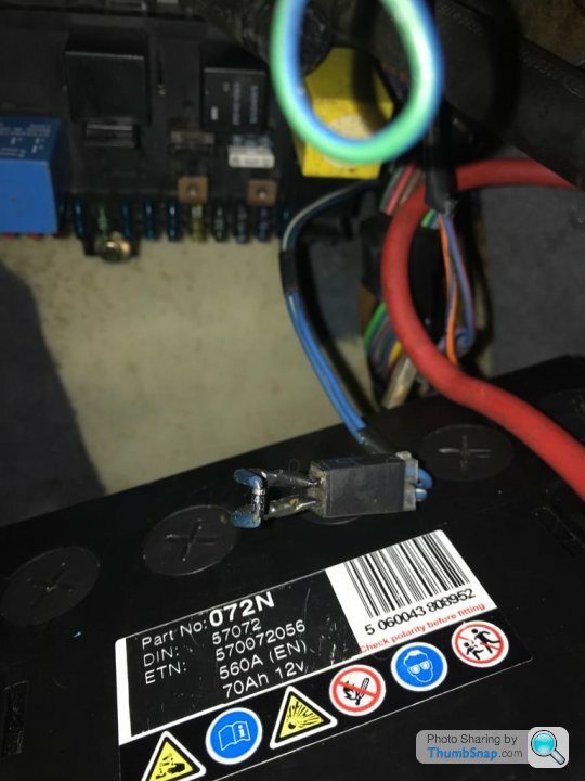
I'm focusing on the diode now and doing research of old threads on here. Thanks for planting the seed a few posts back.
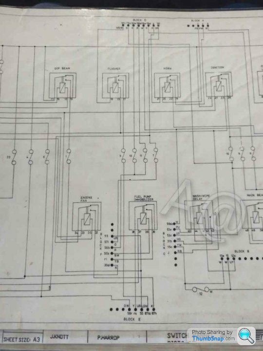
Looking at a wiring diagram for a 92 Griff with this rist board I am seeing that the Hazards are running twin relays.
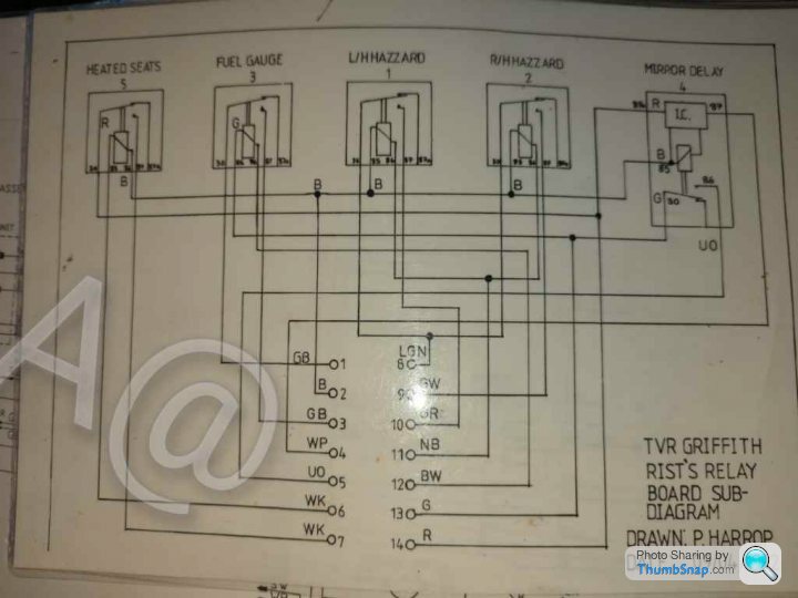
The fuse for the indicator is number 5 (follows on from the main 92 diagram that is everywhere)
and the blue/white-doide-blue/red diode is unrelated to the indicators.
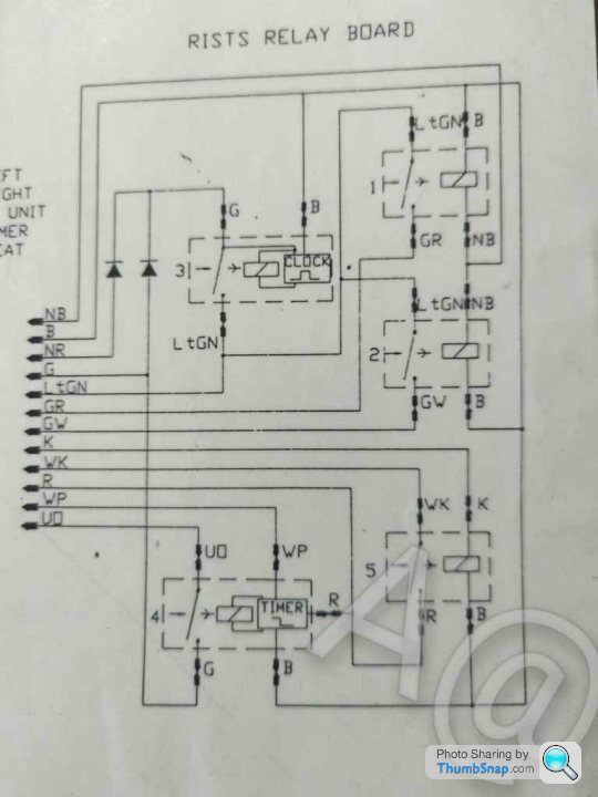
(I can see where the diodes in the system may come from here on a 96 car diagram where heated seats are added to the rist board)
A@
The fuse for the indicator is number 5 (follows on from the main 92 diagram that is everywhere)
and the blue/white-doide-blue/red diode is unrelated to the indicators.
(I can see where the diodes in the system may come from here on a 96 car diagram where heated seats are added to the rist board)
A@
Ah thank you; yes this is the wiring I have!
Shame that diode is not the one then. Does another exist that I should be looking for?
At my indicator stalk switch, I have the LG/N, and the 2 indicator wires G/W and G/R. Am I supposed to have supply to the LG/N with ignition on (and then I make the circuit with the G/W or G/R when throwing the switch?
If I start experimenting with a test live feed to things, do I risk blowing anything worse than a fuse?
Im no expert on flasher units but if you were to rig up a 21 watt test lamp, ground one wire and connect the other to the LG/N terminal at the stalk the lamp should flash.
If it did it proves the circuit to the stalk is ok.
Happy to be corrected on that, not sure what kind of load the flasher unit expects.
If it did it proves the circuit to the stalk is ok.
Happy to be corrected on that, not sure what kind of load the flasher unit expects.
I did exactly this with ignition on, and I get nothing at the LG/N on the stalk. I still don't know if I'm expecting this LG/N at the stalk to be live with ignition on? I'm tempted to start feeding a temporary test 12v straight off the battery to these wires at the stalk and see what happens.
When I turn the hazard switch on, my test light will flash in time with the indicators when touched on any of the wires at the stalk (LG/N, BR and BW).
If all else fails I might just tap in a new igntion switched 12v feed to the LG/N at the stalk.
When I turn the hazard switch on, my test light will flash in time with the indicators when touched on any of the wires at the stalk (LG/N, BR and BW).
If all else fails I might just tap in a new igntion switched 12v feed to the LG/N at the stalk.
With ignition on, if I put a live straight from the battery onto the LG/N terminal at the switch, the switch will activate the indicators when thrown, but on solid (not flashing).
I think I'm just going to buy a flasher unit and wire it up like the below. I know it's a botch, but I'm at a loss now.
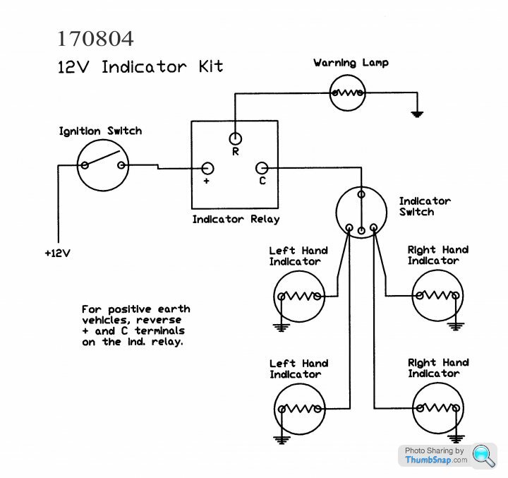
I think I'm just going to buy a flasher unit and wire it up like the below. I know it's a botch, but I'm at a loss now.
Just as an update, I took a feed off the remote switch at the radio and connected it to the power wire at the indicator stalk via a £2.60 flasher relay unit. A bodge I know, but at least the indicators work now (while sat in the garage anyway....yet to actually start it up and drive it).
Gassing Station | Griffith | Top of Page | What's New | My Stuff