Raspberry Pi project
Discussion


Oh my god, thought my soldering iron was ok, got a £50 Maplin soldering station off Amazon, what a revelation, a joy to use and so much more accurate and easy to get things to do what you want, it does what you think it should do, thinner gauge solder thai snt 11 years old helps as well.

Am progressing slowly with this, got my garage set up to do the stuff rather than my work desk, have to stand up but there is a pc, decent light, magnifier etc.
Was pondering where to put the display for the fist tank monitor, cut a hole in the cabinet etc etc, was thinking ti might look cool if I put it in the tank but obviously would need to be properly waterproof, do you think it is possible to put a display (not sure what type yet) in something, underwater and run a cable to it, was thinking of using an ethernet cable as it has multiple cores to the pins on the display, my current 2 line one needs like 8 wires so that works but would it be possible to water proof long term, would look cool stuck on the inside but not if it fills with water, electrocutes/poisons all my fish !
Was pondering where to put the display for the fist tank monitor, cut a hole in the cabinet etc etc, was thinking ti might look cool if I put it in the tank but obviously would need to be properly waterproof, do you think it is possible to put a display (not sure what type yet) in something, underwater and run a cable to it, was thinking of using an ethernet cable as it has multiple cores to the pins on the display, my current 2 line one needs like 8 wires so that works but would it be possible to water proof long term, would look cool stuck on the inside but not if it fills with water, electrocutes/poisons all my fish !
You can use a PCF8574 behind your display, and then connect that to your Arduino using i2c - it only needs 4 pins then.
See this howto
You can buy the modules on Ebay for £1.09
Ralph Bacon has a good explanation on how to use i2c with the PCF8574 module on his video blog he has several other good Arduino videos as well.
See this howto
You can buy the modules on Ebay for £1.09
Ralph Bacon has a good explanation on how to use i2c with the PCF8574 module on his video blog he has several other good Arduino videos as well.
Yes I'd think twice about long term submersion of electronics.
As you say, unless you suspend it in a block of clear resin, it's unlikely you'll achieve 100% water resistance - and then you still potentially have the issue of condensation, heat variations etc. as IIRC tropical* tanks tend to have the water quite warm?
I would have thought the display will remain fairly clear if pressed right up against the glass on the back of the tank, and it'll give the fish something to look at too :-)
- Assuming your tank is tropical!
TonyRPH said:
Yes I'd think twice about long term submersion of electronics.
As you say, unless you suspend it in a block of clear resin, it's unlikely you'll achieve 100% water resistance - and then you still potentially have the issue of condensation, heat variations etc. as IIRC tropical* tanks tend to have the water quite warm?
I would have thought the display will remain fairly clear if pressed right up against the glass on the back of the tank, and it'll give the fish something to look at too :-)
Yeah, tropical, the pump and heater manage ok but they are designed from the outset to be submerged, but behind is fine, have ordered a couple of four line ones, they are so cheap, £5.69, in fact most of the stuff for this stuff is cheap these days, in the 90s, last time i had the urge for doing electronics, stuff like this was expensive, Ebay and Amazon are a godsend, the starter kit for Arduino is marvellous, thirty quid and it includes so much stuff, amazing present for technically inclined kids.As you say, unless you suspend it in a block of clear resin, it's unlikely you'll achieve 100% water resistance - and then you still potentially have the issue of condensation, heat variations etc. as IIRC tropical* tanks tend to have the water quite warm?
I would have thought the display will remain fairly clear if pressed right up against the glass on the back of the tank, and it'll give the fish something to look at too :-)
- Assuming your tank is tropical!
have got it up and running to sense the temp, display it and produce an audible noise if it goes out of bounds.
All a bit breadboard based for now but still lots of work to do on the functionality.
Next steps are to get it texting me and perhaps make it so it can run if the mains drops out as that is the main cause of the temp dropping I expect so it is cock all use if it goes off.
All a bit breadboard based for now but still lots of work to do on the functionality.
Next steps are to get it texting me and perhaps make it so it can run if the mains drops out as that is the main cause of the temp dropping I expect so it is cock all use if it goes off.
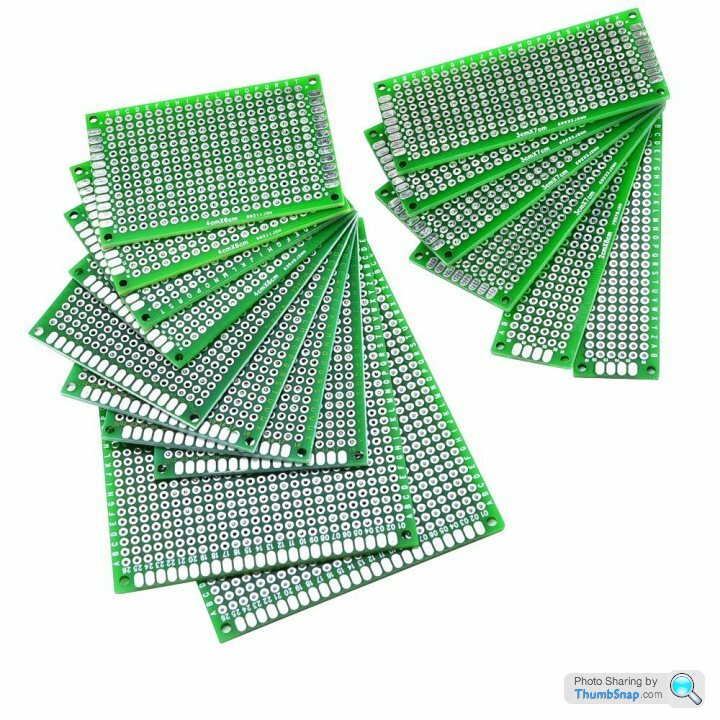
I use these proto boards
It's the same layout as breadboard, but instead you actually solder the parts in.
So it's easy to move from breadboard prototype to finished product (unless you want to get a board made of course).
£10 for 16 boards of differing sizes.
It's the same layout as breadboard, but instead you actually solder the parts in.
So it's easy to move from breadboard prototype to finished product (unless you want to get a board made of course).
£10 for 16 boards of differing sizes.
There are also proto-boards available using the Arduino form-factor - solder on some headers, and you have a custom-made Arduino shield. The official Arduino proto-shield has a lot of space devoted to an SMD device pin-out, but there are plenty of others which just have a 0.1 inch pin matrix. Note that these are typically a matrix, rather than strips like veroboard, so you'll have to solder-bridge the connections.
Sadly, the Arduino header pattern isn't all on a 0.1 inch spacing, otherwise you could just use veroboard and some headers to make a shield - not quite sure why they did that.
Sadly, the Arduino header pattern isn't all on a 0.1 inch spacing, otherwise you could just use veroboard and some headers to make a shield - not quite sure why they did that.
ash73 said:
eharding said:
Note that these are typically a matrix, rather than strips like veroboard, so you'll have to solder-bridge the connections.
I was going to ask about that, the one linked above just looks like a matrix of holes. How do you bridge them?I think I might look for one with power rails and so on.
Cool, will give that a go.
Have got a cheapy GSM module, that is my next task, getting it to text me.
its a long term project, may take a while, cant understand why when I work in IT on databases which is driving me mad, why this is so therapeutic as it is not a million miles off, i think it is perhaps I exist in chaos due to lack of resource, so this I get to do at my own pace to my own standards. Should really spend some time on a CV and have a change of scenery, maybe a job with more than four DBA's to 600 odd DB servers.
@J4CKO
Here's a couple of videos you might find useful:
Web Enable your Arduino (ENC28J60 or W5100 Ethernet Controller)
And;
Send EMAIL from your Arduino! Better HTML! Time Server! More!
Here's a couple of videos you might find useful:
Web Enable your Arduino (ENC28J60 or W5100 Ethernet Controller)
And;
Send EMAIL from your Arduino! Better HTML! Time Server! More!
ash73 said:
<snip>
I tried bridging the holes with solder but got nowhere with that, but it was ok laying bare wire across them and soldering each point.<snip>
(my bold)I tried bridging the holes with solder but got nowhere with that, but it was ok laying bare wire across them and soldering each point.<snip>
That's the way you are supposed to do it.
Usually you'll solder the piece of wire to the first pad, and then follow the desired route bending the wire as required, but remaining over pads, so that you can solder it at each point.
I usually do this, and then only solder a couple of pads at a time, and then once I'm satisfied with the layout, I complete the soldering over the remaining wire / pads.
This is one of mine (audio preamp). here's some s
 tty soldering here though!
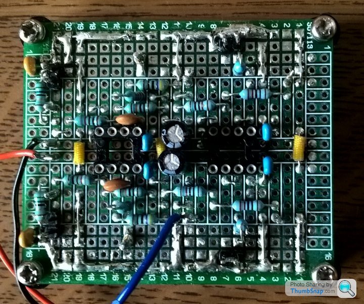
Edited by TonyRPH on Saturday 25th February 08:35
Gassing Station | Computers, Gadgets & Stuff | Top of Page | What's New | My Stuff