Instructions to change fuel maps on 14CUX Griffith, Chimaera
Discussion


Its just to put the correct maps in the two locations- at the moment its a complete lottery what you get if you go from say a TVR 5ltr cat map to the non cat map in the same chip with the tune resistor - it could still be 3.9 Range Rover far as we know. Im sure there are some out there running green tune having popped the cats out that don't have any idea what the map it truly is.
blitzracing said:
Its just to put the correct maps in the two locations- at the moment its a complete lottery what you get if you go from say a TVR 5ltr cat map to the non cat map in the same chip with the tune resistor - it could still be 3.9 Range Rover far as we know. Im sure there are some out there running green tune having popped the cats out that don't have any idea what the map it truly is.
Probably running the LimpHomeMap, Map 0, if the tune resistor is involved.Perhaps a 'Correct TVR Fuel Map Check' could be included in the car's service schedule and offered by TVR specialists and tuners? All they would need is RoverGauge and TunerPro, or similar.
I've already mentioned the 'NAS lockout tune resistor so one map only' solution a few pages back, and Dan thinks it's feasible, this might be an alternative approach.
davep said:
blitzracing said:
It would be nice to do own own TVR super chip along the following lines:
Use the latest "operation pride" base tune with the better stepper and cold start control.
Enable the MIL lamp.
Raise the idle to 850 RPM (over the Range Rover setting)
Put both Cat and Non cat maps for any given engine size for those running decatted manifolds.
It would be really good to use Dans extended and smoothed RPM banding to take the fueling to 6200 rpm instead of 5400 rpm (or so) but that needs time on the rollers with example engines thats a whole new ball game, so it would just be a case of sticking with the TVR map as is at the moment. Im sure this is all do able. Im a bit tied up at the moment with knocking down my garage and trying to get a new one built before the winter, so stuff like this is on the "to do" list at the moment.
Looking at the configure build list in Dan's Version 2 code I think the first two in the list can be done as of now:Use the latest "operation pride" base tune with the better stepper and cold start control.
Enable the MIL lamp.
Raise the idle to 850 RPM (over the Range Rover setting)
Put both Cat and Non cat maps for any given engine size for those running decatted manifolds.
It would be really good to use Dans extended and smoothed RPM banding to take the fueling to 6200 rpm instead of 5400 rpm (or so) but that needs time on the rollers with example engines thats a whole new ball game, so it would just be a case of sticking with the TVR map as is at the moment. Im sure this is all do able. Im a bit tied up at the moment with knocking down my garage and trying to get a new one built before the winter, so stuff like this is on the "to do" list at the moment.
Edited by blitzracing on Friday 11th July 13:00
;----------------------------------------------------------
; These flags control how the code section is built
; This section should not be altered.
;----------------------------------------------------------
BUILD_R3365             = 0
BUILD_R3383             = 1
BUILD_R3652             = 0
BUILD_R3360_AND_LATER   = 0
BUILD_TVR_CODE          = 0
NEW_STYLE_AC_CODE       = 0
NEW_STYLE_FAULT_SCAN    = 0
NEW_STYLE_FAULT_DELAY   = 0
NEW_STYLE_MIL_CODE      = 0
Raising the idle shouldn't be difficult.
Not sure I fully understand the 'Put both Cat and Non-cat maps ... for decatted manifolds' requirement. As you know there are five fuel map areas available for use (already set up for open and/or closed loop) then it's just a question of designating tune resistor values to their specific engine configurations (or use CRASM build control flags as above) and then lots of tweaking in the respective code paths.
I'm big headed enough to say I could easily knock up your TVR super chip to your specification and you could re-map the 3.9 extended fuel table with your AFR gauge and my time logger. I was pleasantly surprise how well the re-mapping worked with my AFR logger even though it was very time consuming. In the winter I'll have ago at writing a program to automatically merge the RG and AFR logs.
I personally would rather wait for Dan's version 3 as I don't like the overrun in the later Land Rover revisions plus the idle control improvements in the later TVR version are good enough.
Dave,
I'm sure you realise when building the different versions always start with the correct data.ams file and don't just change the BUILD_ Rxxxx directives as the data after map 5 varied with the different revisions.
Your right changing the idle speed is very very easy now we know how plus using all 5 maps is a good idea and work really well.
I now run R2967 code but with a modified R2422 430 map 2 and 450 map5. During re-mapping I would often load maps 1, 2 & 3 with three different sets of test fuel tables so I could easily switch test fuel maps in the work car park without anyone knowing how special I am.
Dan
You'll be please to hear I've been putting you rebuild project to good use and now do all my mods in version 2 so I can pretend I'm a real computer programmer.
Mark,
Great to see you again at the Berkshire meeting. Thanks for helping me log my speed sensor in the pub car park at 3mph and thanks for checking Phil's ECU fault codes as it's his car we pinched the Chimmy 400 cat prom from.
Thanks again for lending me your logger.
I bet Dave doesn't have so much fun at his local TVR meetings.
Cheers, Steve
I'm trying to understand the overrun behavior differences between older and newer code since this is the feature that seems to be mentioned often. Ideally, we would use the latest code since it has a number of improvements but tailor the overrun to personal taste.
Steve, very early in this thread you mentioned transferring your fuel map into a 94 Land Rover version of code and you stated that the overrun was much quieter (and unacceptable). Do you remember if you transferred the whole fuel map data structure (including the throttle rate table) or just the 8 by 16 fuel map matrix?
Dave, later in the thread you also mention liking the R2422 tune for, I assume, the same reason. You state that it pops and bangs on overrun. It would help if we understood whether the overrun differences are due to the code itself or just differences in the data section.
danbourassa said:
I'm trying to understand the overrun behavior differences between older and newer code since this is the feature that seems to be mentioned often. Ideally, we would use the latest code since it has a number of improvements but tailor the overrun to personal taste.
Steve, very early in this thread you mentioned transferring your fuel map into a 94 Land Rover version of code and you stated that the overrun was much quieter (and unacceptable). Do you remember if you transferred the whole fuel map data structure (including the throttle rate table) or just the 8 by 16 fuel map matrix?
Dave, later in the thread you also mention liking the R2422 tune for, I assume, the same reason. You state that it pops and bangs on overrun. It would help if we understood whether the overrun differences are due to the code itself or just differences in the data section.
Dan, Steve, very early in this thread you mentioned transferring your fuel map into a 94 Land Rover version of code and you stated that the overrun was much quieter (and unacceptable). Do you remember if you transferred the whole fuel map data structure (including the throttle rate table) or just the 8 by 16 fuel map matrix?
Dave, later in the thread you also mention liking the R2422 tune for, I assume, the same reason. You state that it pops and bangs on overrun. It would help if we understood whether the overrun differences are due to the code itself or just differences in the data section.
It’s good to hear from you, I was just going to bed but this is worth my immediate attention. Plus you must have over heard my telephone conversation this evening with Dave on the very same subject.
I confirm running R3833 and R3526 with the complete data structure (inc throttle/coolant tables & scalars etc)for maps 1 to 5 from R2967 or TVR R2422 kills the overrun fuelling down to 1,300 rpm and can start as low as 1,550rpm, as opposed to 2,500rpm in the TVR prom. I’m not changing any data in R3833 and R3526 above map 1 except the idle or below map 5 except the RPM table.
My AFR gauge clearly shows when the fuel is cut and unfortunately cutting the fuel lower makes the car shunty and lurchy as the fuel is turned on and off. There must be a minimum cut in rpm set point and a lower restart set point.
I would be more than happy to run some tests with different code/data combinations to help identify where the overrun limits are stored, your wish is my command.
Night, Steve
P.S. Dave makes a great assembler teacher.
P.S.S I hope you've seen the results of your hard work on my Growl rolling road graph, in particular the extended RPM to 6,200 that I now permanently run.
Edited by stevesprint on Friday 18th July 22:50
Dan,
I’ve just been incredibly reckless and been for a drive with R3383 data and R2967 code and the fuel overrun cut could start as low as 1,550 rpm like with the later proms. This proves there is an overrun setting in the Data as Dave thought. Once the overrun fuel is cut both the old and new proms would restart the fueling with exactly the same behaviour at about 1,300rpm.
To be clear C000 to C7FF was from R3383 except fuel maps 1-5 (complete structure) that were from R2967. C800 to FFFF was from R2967 except your extended RPM table. Therefore we are looking for a parameter in the data section (excluding the fuel maps) that sets the minimum RPM the overrun fuel cut can start.
I might have to start testing half then quarter etc of the data section as and when I'm out for drives next, like a binary chop search. Maybe I could be more scientific and look for hex values close to 1,500 or 2,500 rpm. Oh no not rpm’s as they are usually expressed as spark period units of 2 uSec and involve the magic number of 7,500,000. Therefore is 2,500 rpm $0BB8 (2 uSec) and is 1,500 rpm $1388 (2 uSec)
I don’t understand why I’m like a dog with a bone but at least Mark Adams, Steve Heath or the Stig haven’t given the game away and spoilt our fun.
Edited by stevesprint on Saturday 19th July 00:13
Steve, I think this is good news. Once we figure this out, it will expand our understanding of the code and give us more tuning options.
I did see your rolling road graph. It's interesting to me that you can see the performance result of the glitch in the RPM curve. You have proven the importance of having a smooth curve.
I did see your rolling road graph. It's interesting to me that you can see the performance result of the glitch in the RPM curve. You have proven the importance of having a smooth curve.
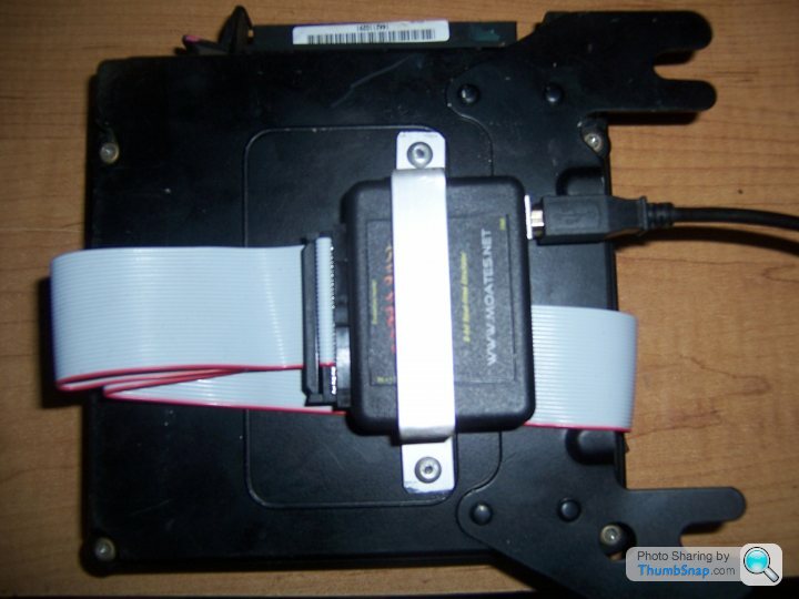
Can one of you clever people tell me how to sort the Checksum in Tuner pro? Ive got the emulator working a treat on a spare ECU, so I can copy maps to and from the ECU with the touch of a button. Ive set Tuner pro to show the fuel maps in Hex, so they tally with RoverGauge. If I edit a load point and try and save the map- it complains the checksum is wrong, so it wont save. I thought it would be a case of saving the file, then using the 14CUX toolkit to correct the checksum, but I cant get that far. Whats the correct process to save a modified map before writing it to the emulator?
blitzracing said:
Can one of you clever people tell me how to sort the Checksum in Tuner pro?
Mark, Download www.stevesprint.com/remap-14cux/TunerPro-xdf.zip and copy 14CUX_CHECKSUM2.0.dll into "C:\Program Files\TunerPro RT" directory
Call me if you have any issues, Enjoy.
Steve
P.S. I'm not one of the clever people.
I'm not clever either, but further to the ‘MIL_DELAY control flag in a TVR revision’ discussion above I’ve had a look at the code to try and determine how the MIL lamp function is enabled, and when it is switched On and Off. This may get ‘nerdy’ and beyond the scope of Steve's thread, but some use may come of it.
Consider the MIL_DELAY control flag handling code, as shown here in Dan’s mainLoop ASM build file:
The instruction ldaa XC7C2 loads the contents of memory address $C7C2, which is set with a value of $00 or $FF (the value of the MIL control flag discussed above), into Accumulator A.
Instruction bne (branch if not equal) checks if the Z(ero) bit in the Code Condition Register (CCR) was set in the previous ldaa instruction. Z is set if the loaded value is $0000; cleared otherwise. If clear ($FF then MIL is to be enabled) the code branches to the offset defined by the label LCA6C. If Z is set ($00 MIL is to be disabled) the code will continue with the next offset.
With MIL set as disabled a ldaa instruction loads the contents of port1data, which is initialised with a value $02, into Accumulator A. Port 1 is a mode independent 8-bit I/0 and timer port. Each line can be configured as either an input or output as defined by the port 1 data direction register. The line functions for port1data are:
As we know during MPU register initialisation port1data is set for $02. So port1data contents are 00000010, meaning P10 is Low and the MIL lamp can be enabled. But with $02 loaded in Acc A, the Inclusive OR instruction oraa performs logical OR on the contents of Acc A and #$01 (in memory), like so OR (1+0=1, 0+1=1, and 1+1=1); giving 00000011 in our example. This resultant value of $03 is now stored in Acc A and then stored in port1data with staa. So port1data contents are now 00000011, meaning P10 is now High and the MIL lamp cannot be switched On.
However, if the MIL control flag is set as $FF the code branches to L6A6C, where a full scan of the fault codes is conducted. If the resultant fault code is not zero the contents of port1data (containing $02) and a value of $FE are ANDed to drive P10 Low to switch the MIL EFI lamp On.
Steve has reported that when he changed the MIL_CONTROL flag from $00 to $FF in a TVR revision of the code there was still no MIL EFI lamp On when a fault was induced. Looking at the logic above the possible causes for this may be:
-port1data’s value of $03 has not been re-initialised or cleared to $02,
-the result of the fault scan codes procedure is always zero for some reason,
-the fault fell outside of the fault scan range, the scan is a bit flakey.
So more analysis is needed.
Consider the MIL_DELAY control flag handling code, as shown here in Dan’s mainLoop ASM build file:
;---------------------------------------
;              Service MIL
;
; If data value at XC7C2 is zero, turn
; MIL off and branch to next section.
; For NAS, value is $FF.
;---------------------------------------
                ldaa        $C7C2               ; value will be $FF or $00 (MIL delay)
                bne         .LCA6C              ; branch if not zero
                ldaa        port1data
                oraa        #$01                ; EFI warning light OFF
                staa        port1data
                bra         Write9x00           ; this is just a big waste of time
The instruction ldaa XC7C2 loads the contents of memory address $C7C2, which is set with a value of $00 or $FF (the value of the MIL control flag discussed above), into Accumulator A.
Instruction bne (branch if not equal) checks if the Z(ero) bit in the Code Condition Register (CCR) was set in the previous ldaa instruction. Z is set if the loaded value is $0000; cleared otherwise. If clear ($FF then MIL is to be enabled) the code branches to the offset defined by the label LCA6C. If Z is set ($00 MIL is to be disabled) the code will continue with the next offset.
With MIL set as disabled a ldaa instruction loads the contents of port1data, which is initialised with a value $02, into Accumulator A. Port 1 is a mode independent 8-bit I/0 and timer port. Each line can be configured as either an input or output as defined by the port 1 data direction register. The line functions for port1data are:
| Port | Direction | Level | Purpose |
|---|---|---|---|
| P10 | Output | High | MIL |
| P11 | Output | High | Purge Valve (uses MPU Timer 2) |
| P12 | Output | High | Even Injector Bank (uses Timer 3 and T4 transistor) |
| P13 | Output | High | Condensor Fan Timer |
| P14 | Output | Low | Stepper Motor Drive 1 |
| P15 | Output | Low | Stepper Motor Drive 2 |
| P16 | Output | Low | Fuel Pump Relay (defaults to ON) |
| P17 | Output | Low | Stay Alive Toggle |
As we know during MPU register initialisation port1data is set for $02. So port1data contents are 00000010, meaning P10 is Low and the MIL lamp can be enabled. But with $02 loaded in Acc A, the Inclusive OR instruction oraa performs logical OR on the contents of Acc A and #$01 (in memory), like so OR (1+0=1, 0+1=1, and 1+1=1); giving 00000011 in our example. This resultant value of $03 is now stored in Acc A and then stored in port1data with staa. So port1data contents are now 00000011, meaning P10 is now High and the MIL lamp cannot be switched On.
However, if the MIL control flag is set as $FF the code branches to L6A6C, where a full scan of the fault codes is conducted. If the resultant fault code is not zero the contents of port1data (containing $02) and a value of $FE are ANDed to drive P10 Low to switch the MIL EFI lamp On.
Steve has reported that when he changed the MIL_CONTROL flag from $00 to $FF in a TVR revision of the code there was still no MIL EFI lamp On when a fault was induced. Looking at the logic above the possible causes for this may be:
-port1data’s value of $03 has not been re-initialised or cleared to $02,
-the result of the fault scan codes procedure is always zero for some reason,
-the fault fell outside of the fault scan range, the scan is a bit flakey.
So more analysis is needed.
danbourassa said:
I'm trying to understand the overrun behavior differences between older and newer code since this is the feature that seems to be mentioned often. Ideally, we would use the latest code since it has a number of improvements but tailor the overrun to personal taste.
Dan,I’ve finally found the location for the overrun setting is at prom offset 137, it’s $10 for Land Rover and $0A for TVR 400Cat(R2967-9B). It’s not the same for all TVR proms and explains why I always preferred and use R2967-9B for the TVR 400Cat.
Your comment in data.asm at line 179 or 180 “ICI, compared with upper byte of filtered ign. period” should have given me a hint but I didn’t test it earlier as the values are not what I was expecting. What I can’t understand is why its $09 in my original R2422 430 prom, at least I still have an excuse to carry on experimenting.
Arr, please confirm the ign. period is the spark to spark time in 2 uSec therefore the lower the figure the faster the engine is running? It's dividing by that magic number thingy again 7,500,000, therefore prom offset 137 should be lower for TVR like in R2422 not higher as in R2967-9B, I'm confused.
The main thing is now your version 3 can be configured to make TVR owners smile on overrun.
Edit
The overrun fuel is not cut within the first minute of driving even with a hot engine and maybe a use for one of the mysteryDownCounter’s.
Edited by stevesprint on Tuesday 22 July 19:52
stevesprint said:
Arr, please confirm the ign. period is the spark to spark time in 2 uSec therefore the lower the figure the faster the engine is running?
Yes, this is correct. Using the period instead of the frequency also flips the polarity of a conditional test, so it can be confusing. I sometimes refer to the left two columns in the RPM table as a quick reference to get my bearings. If the C137 values don't make sense on their own, it may be that other factors are involved. The area of code where it's used is still a bit of a puzzle.stevesprint said:
The overrun fuel is not cut within the first minute of driving even with a hot engine and maybe a use for one of the mysteryDownCounter’s.
It may be the 'mysteryDownCounter' or the 'startupFuelTime' (X009C). I will try to flowchart this section of code when I have time. You might have the whole thing figured out by then.danbourassa said:
Yes, this is correct. Using the period instead of the frequency also flips the polarity of a conditional test, so it can be confusing.
Dan, Thanks for confirming. With all the excitement of finding the overrun prom location I wasn't thinking logically with the data values. Fortunately my test results below now make perfect sense.
Revison  C137     RPM
R3383     10     1,600     Standard Land Rover
R2967     10     1,600
R2967     0A     2,650     Standard 400 Cats
R3383     0A     2,650
R3383     09     2,750
R3833     07     3,400
R3383     04    +5,000??


Here's the standard values from the TVR proms (its 10 in all Land Rover Proms, old and new)

400 PreCat  10  (1,600)
430 & BV    09  (2,750)
400 Cat     0A  (2,650)
450 Cat     10  (1,600)
500 1994    10  (1,600)
500 1995    0A  (2,650)
Please note the RPM readings above are from the dash rpm counter and therefore are only a rough guide.
As it's a great time of year for test driving the 14CUX please do not hesitate to let me know if their are any other prom locations that need finding or testing.
Edited by stevesprint on Thursday 24th July 20:27
davep said:
I'm not clever either, but further to the ‘MIL_DELAY control flag in a TVR revision’ discussion above I’ve had a look at the code to try and determine how the MIL lamp function is enabled, and when it is switched On and Off. This may get ‘nerdy’ and beyond the scope of Steve's thread, but some use may come of it.
Consider the MIL_DELAY control flag handling code, as shown here in Dan’s mainLoop ASM build file:
;---------------------------------------
; Service MIL
;
; If data value at XC7C2 is zero, turn
; MIL off and branch to next section.
; For NAS, value is $FF.
;---------------------------------------
ldaa $C7C2 ; value will be $FF or $00 (MIL delay)
bne .LCA6C ; branch if not zero
ldaa port1data
oraa #$01 ; EFI warning light OFF
staa port1data
bra Write9x00 ; this is just a big waste of time
Dave,Consider the MIL_DELAY control flag handling code, as shown here in Dan’s mainLoop ASM build file:
;---------------------------------------
; Service MIL
;
; If data value at XC7C2 is zero, turn
; MIL off and branch to next section.
; For NAS, value is $FF.
;---------------------------------------
ldaa $C7C2 ; value will be $FF or $00 (MIL delay)
bne .LCA6C ; branch if not zero
ldaa port1data
oraa #$01 ; EFI warning light OFF
staa port1data
bra Write9x00 ; this is just a big waste of time
Thanks for getting all nerdy, I secretly like it but please don’t tell everyone.
To help me understand what’s going on above please can you confirm when port1data contains $03 both P10 and P11 are disabled (MIL and purge valve)? Also please confirm that enabled means the MIL lamp is actually illuminated or it can be illuminated.
To help identify the issue would changing the beq instruction to brn (branch never), in the code below, force the MIL lamp on even if there are no fault codes.
;---------------------------------------------------------------------------
; This is the way the fault checking is done in older code (including TVR).
; This method is not as good since unused bits can get through the mask
; and set the MIL.
;---------------------------------------------------------------------------
                                               ; scan for set fault bits
.LCA6F       ldaa          faultBits_4D
             anda          #$EF                ; mask out bit 4 (DTC 59 -- Group Fault)
             oraa          faultBits_4B        ; OR in all bits from faultBits_4B
             oraa          faultBits_4C        ; OR in all bits from faultBits_4C
             anda          #$F0                ; low nibble unused for all three
             oraa          faultBits_49        ; OR in all bits from faultBits_49
             oraa          faultBits_4A        ; OR in all bits from faultBits_4A
             beq           Write9x00           ; if zero, no faults, branch ahead

             ldaa          port1data
             anda          #$FE                ; EFI warning light ON
             staa          port1data
stevesprint said:
To help me understand what’s going on above please can you confirm when port1data contains $03 both P10 and P11 are disabled (MIL and purge valve)? Also please confirm that enabled means the MIL lamp is actually illuminated or it can be illuminated.
To help identify the issue would changing the beq instruction to brn (branch never), in the code below, force the MIL lamp on even if there are no fault codes.
Without sight of the 14CUX PCB schematic I cannot confirm what happens between portdata1 and the unit connector, but I think it's reasonable to assume that with P10 set high the MIL lamp will be inhibited or cannot be illuminated. By MIL lamp enabled I mean can be illuminated in the event of a fault.To help identify the issue would changing the beq instruction to brn (branch never), in the code below, force the MIL lamp on even if there are no fault codes.
;---------------------------------------------------------------------------
; This is the way the fault checking is done in older code (including TVR).
; This method is not as good since unused bits can get through the mask
; and set the MIL.
;---------------------------------------------------------------------------
                                               ; scan for set fault bits
.LCA6F       ldaa          faultBits_4D
             anda          #$EF                ; mask out bit 4 (DTC 59 -- Group Fault)
             oraa          faultBits_4B        ; OR in all bits from faultBits_4B
             oraa          faultBits_4C        ; OR in all bits from faultBits_4C
             anda          #$F0                ; low nibble unused for all three
             oraa          faultBits_49        ; OR in all bits from faultBits_49
             oraa          faultBits_4A        ; OR in all bits from faultBits_4A
             beq           Write9x00           ; if zero, no faults, branch ahead

             ldaa          port1data
             anda          #$FE                ; EFI warning light ON
             staa          port1data
I'd just comment out the beq line to test the lamp.
Dan, I'm having a few problems getting the 'logic' to work on the setup and initialisation of portdata1 and portdata2. My start point was the table for port initialisation in the Reset Entry ASM (as in my previous post), upon further analysis I think the table may be incorrect for the following reasons:
- the initialisation value for ports 1 and 2 is $0F02, looking at the table I think this value has been applied with the MSB at the wrong bit/pin position
- breaking the dataword into bytes, $0F should be used for portdata2 not portdata1; this then establishes MPU operating mode at RESET (which is latched via SC1-3, the three most significant bits of portdata2)
- the LSB of $02 should be applied to portdata1.
Now here comes the rub, I'm still not sure how the port direction initialisation code of $FFFE for the portdrr1 (and portdrr2???) works. Using the MSB convention and port allocation used for $0F02, a value of $FFFE means all port lines are Outputs except P10, which is an Input (our old friend the MIL lamp). Any thoughts?
Edited by davep on Thursday 31st July 09:20
Dave, writing the 16-bit value $0F02 to address X0002/03 loads $0F into X0002 (Port 1) and $02 into X0003 (Port 2) which, I believe, is correct. I think that the Mode is set by the condition of the 3 lines as soon as power is applied and has nothing to do with the data that is written to this port. The datasheet states that the 3 lines are latched when the MPU comes out of reset. This would be before any code is executed. Although we don't have a schematic, I think we can infer that these lines are lightly held high or low as needed to achieve Mode 2. The resistor values would be high enough to become transparent to the normal board operation.
As far as the data direction...are you being a little-endian Intel-head?
As far as the data direction...are you being a little-endian Intel-head?
danbourassa said:
Dave, writing the 16-bit value $0F02 to address X0002/03 loads $0F into X0002 (Port 1) and $02 into X0003 (Port 2) which, I believe, is correct. I think that the Mode is set by the condition of the 3 lines as soon as power is applied and has nothing to do with the data that is written to this port. The datasheet states that the 3 lines are latched when the MPU comes out of reset. This would be before any code is executed. Although we don't have a schematic, I think we can infer that these lines are lightly held high or low as needed to achieve Mode 2. The resistor values would be high enough to become transparent to the normal board operation.
As far as the data direction...are you being a little-endian Intel-head?
There in lies the problem, I was looking at port1data, port1drr simply as registers, and also I had my Intel or DEC hat on. Thanks Dan, back to big-endian it is then.As far as the data direction...are you being a little-endian Intel-head?
I knew it!

Gassing Station | Griffith | Top of Page | What's New | My Stuff