Crossram build
Discussion


I tossed out the Ultima bolts and got some ARP bolts drilled some holes for safety wires, I never hurts to be safe. In the past I have found that most bolts fall off of these types of cars due to the hard driving they go through, so many of the bolts will be safety wired. [ur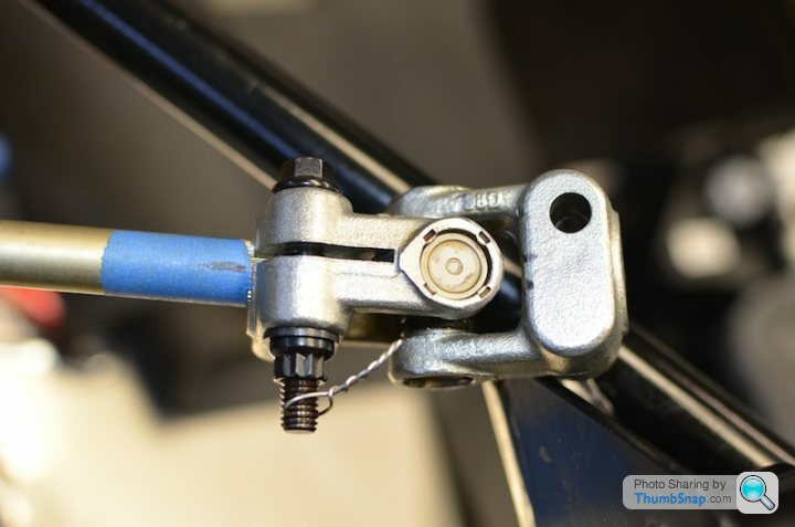 |http://thumbsnap.com/oKyWuuUn[/url]
|http://thumbsnap.com/oKyWuuUn[/url]Edited by crossram on Thursday 26th December 06:06
crossram said:
I tossed out the Ultima bolts and got some ARP bolts drilled some holes for safety wires, I never hurts to be safe. In the past I have found that most bolts fall off of these types of cars due to the hard driving they go through, so many of the bolts will be safety wired. [ur|http://thumbsnap.com/oKyWuuUn[/url]
Whilst I can relate to the idea of making things as safe as possible I feel, in this case, you have perhaps gone the other way.|http://thumbsnap.com/oKyWuuUn[/url]Edited by crossram on Thursday 26th December 06:06
The Ultima supplied bolts would have been 8.8 grade and include Nyloc nuts which are more than adequate for the task. I have dismantled these joints on 20 year old TVR cars and in some cases have had to cut them off as they are so secure.
It appears, but I could be wrong, that there is no lock washer on your bolt. The lock wire will prevent the bolt from rotating but does not prevent the nut from doing so. It looks like the nut could undo by about 5 turns. The wire will stop the nut and bolt falling out but this is a clamp so the clamping force will be lost and the steering shaft could then spin in the joint with the resultant lose of steering.
If the lock wire had gone through a corner of the nut and a corner of the bolt head then all would be well.
Steve
If you feel the nylocs are not secure enough, you can always try these products: http://www.nord-lock.com/
crossram said:
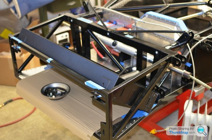
Here are some pictures of my build I made some flanges to keep the hot air out of the cabin for the cables 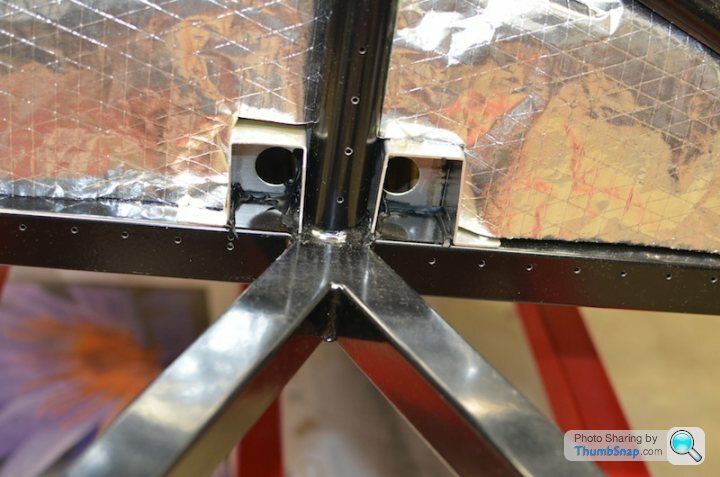
I looked at your photo's.You have a really different approach to solutions, nice!
Let the pictures come so we can give usable comments.
1. Maybe next time put the kit on the outside?
2. other picture: Drill the hole close to the nut and
Steve_D said:
Whilst I can relate to the idea of making things as safe as possible I feel, in this case, you have perhaps gone the other way.
The Ultima supplied bolts would have been 8.8 grade and include Nyloc nuts which are more than adequate for the task. I have dismantled these joints on 20 year old TVR cars and in some cases have had to cut them off as they are so secure.
It appears, but I could be wrong, that there is no lock washer on your bolt. The lock wire will prevent the bolt from rotating but does not prevent the nut from doing so. It looks like the nut could undo by about 5 turns. The wire will stop the nut and bolt falling out but this is a clamp so the clamping force will be lost and the steering shaft could then spin in the joint with the resultant lose of steering.
If the lock wire had gone through a corner of the nut and a corner of the bolt head then all would be well.
Steve
ARP hardware is heat-treated 8740 chromoly They are nominally rated at 180,000 psi tensile strength and provide a substantial extra margin of safety over Grade 8 hardware.They also resist rust and are maintenance-free you can read more here http://arp-bolts.com/ The picture was only for reference, final installation will look a bit different.The Ultima supplied bolts would have been 8.8 grade and include Nyloc nuts which are more than adequate for the task. I have dismantled these joints on 20 year old TVR cars and in some cases have had to cut them off as they are so secure.
It appears, but I could be wrong, that there is no lock washer on your bolt. The lock wire will prevent the bolt from rotating but does not prevent the nut from doing so. It looks like the nut could undo by about 5 turns. The wire will stop the nut and bolt falling out but this is a clamp so the clamping force will be lost and the steering shaft could then spin in the joint with the resultant lose of steering.
If the lock wire had gone through a corner of the nut and a corner of the bolt head then all would be well.
Steve
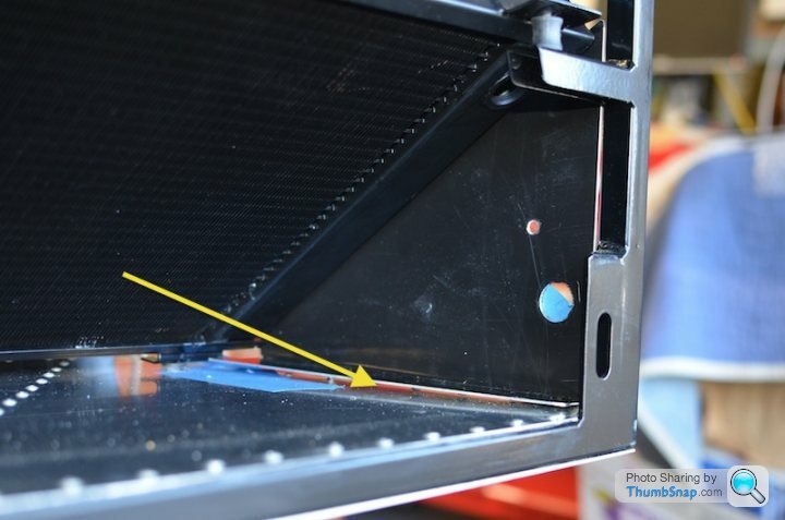
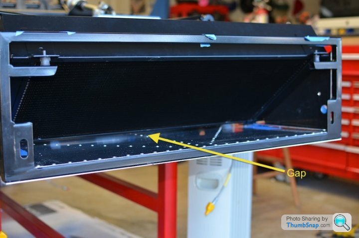
Your kit should include a roll of foam tape. When you look at the tape it looks like it is no more than 3-4mm thick but when you release it from the roll it expands to somewhere around 15mm thick. Unroll a length and cut it to size. Peel back the backing for a short length and secure a tab of masking tape to the end of the backing tape. Lay the backing back onto the tape. Do this to both ends of the tape.
Next is the difficult bit. Squash the tape flat and as quick as possible post it into the gap. Use the tabs to peel back and remove the backing tape whilst the tape is still positioned in the gap.
Steve
Next is the difficult bit. Squash the tape flat and as quick as possible post it into the gap. Use the tabs to peel back and remove the backing tape whilst the tape is still positioned in the gap.
Steve
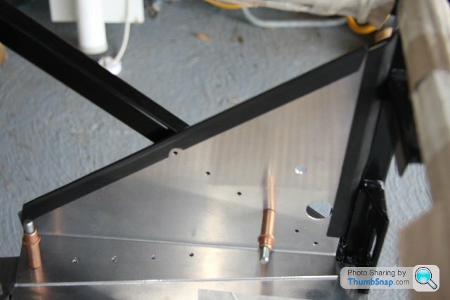
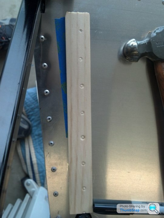
Alternatively, you could do it like this, which is neater than mounting it on top of the other rivets (although if you have already sealed and riveted the panel, you will have some difficulty)
and if you are concerned about heat getting into the cockpit, you could fit an additional plate behind the radiator, like this :-
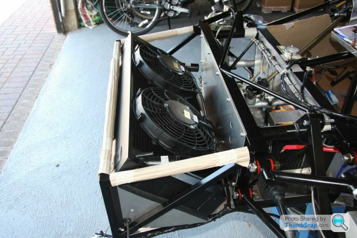
(You will notice that I made that panel removeable)
and if you are concerned about heat getting into the cockpit, you could fit an additional plate behind the radiator, like this :-
(You will notice that I made that panel removeable)
Gassing Station | Ultima | Top of Page | What's New | My Stuff