Sensor adaptor
Discussion


100SRV said:
Hi,
I'd appreciate some help finding an adaptor to take a temperature sensor, there is an unused port 3/4" UNF female and the sensor is 5/8" UNF. I've tried Merlin and Holden (via internet) without success. Any suggestions for likely vendors?
thank you
100SRV
Phone Earls.I'd appreciate some help finding an adaptor to take a temperature sensor, there is an unused port 3/4" UNF female and the sensor is 5/8" UNF. I've tried Merlin and Holden (via internet) without success. Any suggestions for likely vendors?
thank you
100SRV
But you might be as handy buying a -8 fitting which should be 3/4"
Then drilling and tapping it internally to 5/8"
It's an odd fitment really...not even sure if there is physically room to allow it ?
stevieturbo said:
Phone Earls.
But you might be as handy buying a -8 fitting which should be 3/4"
Then drilling and tapping it internally to 5/8"
It's an odd fitment really...not even sure if there is physically room to allow it ?
Hi Stevie,But you might be as handy buying a -8 fitting which should be 3/4"
Then drilling and tapping it internally to 5/8"
It's an odd fitment really...not even sure if there is physically room to allow it ?
thank you, good suggestion...
There is room, I'll explain why.
RV8 running 14CUX EFi
I changed the instrument pack to a custom one I made using a Smiths triple gauge cluster so I can have fuel, oil pressure and coolant temperature in one neat pack. It looks good but the temperature gauge goes to maximum at normal temperatures. I measured the resistance of the stock sender at a range of temperatures and plan B is to use a series resistor to adjust it so the gauge reads correctly.
However...
having rebuilt it years ago as a result of a cooking incident I am VERY wary of bodge fixes and would rather Plan A and use the correct temperature sender - this happens to be 5/8" UNF (unlike the stock one which I think is 1/8" NPT).
There is an unused port on the inlet manifold behind the distributor, plenty of room in front of it for an adaptor and the preferred sensor.
I meant material thickness between 3/4" OD thread and having a 5/8" OD thread tapped inside it.
Not sure if there is physically the room for that ?
A resistor might do the trick, or this device would give you flexibility
https://www.spiyda.com/magento/index.php/vehicle-e...
Or mount the sensor elsewhere ?
Not sure if there is physically the room for that ?
A resistor might do the trick, or this device would give you flexibility
https://www.spiyda.com/magento/index.php/vehicle-e...
Or mount the sensor elsewhere ?
stevieturbo said:
I meant material thickness between 3/4" OD thread and having a 5/8" OD thread tapped inside it.
Not sure if there is physically the room for that ?
A resistor might do the trick, or this device would give you flexibility
https://www.spiyda.com/magento/index.php/vehicle-e...
Or mount the sensor elsewhere ?
Hi,Not sure if there is physically the room for that ?
A resistor might do the trick, or this device would give you flexibility
https://www.spiyda.com/magento/index.php/vehicle-e...
Or mount the sensor elsewhere ?
ah, I understand now - good point! Will have to check OD / ID of each thread. Fortunately the 3/4" UNF plug I have is steel so the material will be a bit stronger than brass.
Resistor:
I've looked at the characteristic of the present sensor having measured resistance against temperature at quite a few points - it is a very pronounced exponential curve. I need to spend a bit of time on this, could be a and easy quick fix.
The fuel gauge wizard is an interesting little gadget! thank you for the link.
Thank you for your help and suggestions.
I found this thread:
http://forum.britishv8.org/read.php?6,36253
might be of use to others who find themselves in a similar position.
http://forum.britishv8.org/read.php?6,36253
might be of use to others who find themselves in a similar position.
100SRV said:
The fuel gauge wizard is an interesting little gadget!
Looks like a right bodge to me! I'm sure it works but setting it up must be a PITA (even there own instructions say:"The wizard is an analogue device, based on op-amps with an FET output. In these days of digital equipment we are used to pressing a couple of buttons to get things done, unfortunately this is not the case with the fuel gauge wizard, calibration is at best awkward, and can be quite tricky for the uninitiated. "
Why not just make a digital one? A suitable AVR or PIC micro that can do that costs less than £1......
Max_Torque said:
Looks like a right bodge to me! I'm sure it works but setting it up must be a PITA (even there own instructions say:
"The wizard is an analogue device, based on op-amps with an FET output. In these days of digital equipment we are used to pressing a couple of buttons to get things done, unfortunately this is not the case with the fuel gauge wizard, calibration is at best awkward, and can be quite tricky for the uninitiated. "
Why not just make a digital one? A suitable AVR or PIC micro that can do that costs less than £1......
When I saw the photo it reminded me of the maplin kits or stuff we'd build as apprentices in the early nineties...we called them "MWARM" projects, apparently MWARM meant "Make Work And Redesign or Modify""The wizard is an analogue device, based on op-amps with an FET output. In these days of digital equipment we are used to pressing a couple of buttons to get things done, unfortunately this is not the case with the fuel gauge wizard, calibration is at best awkward, and can be quite tricky for the uninitiated. "
Why not just make a digital one? A suitable AVR or PIC micro that can do that costs less than £1......
If you are going to mess around with resistors- it will upset the resistance curve of the sensor, so you wont get it correct over the whole range. Your best bet would be to take the point that is most critical- say 95'c and then add a series resistance to get the gauge correct at that temp.
blitzracing said:
If you are going to mess around with resistors- it will upset the resistance curve of the sensor, so you wont get it correct over the whole range. Your best bet would be to take the point that is most critical- say 95'c and then add a series resistance to get the gauge correct at that temp.
Hi Blitz...thank you - exactly what I observed when fiddling around on a spreadsheet, it was pretty obvious from the exponential shape of the sensor that a series resistor wouldn't be a great fix.
I have since carried out a bit of research and a few tests, seems there are two types of sensor with this thread (1/8"-27 NPTF) being:
AMR1425 1/8" - 27 NPTF Has green insulator - PRESENTLY FITTED
AMR3321 1/8" - 27 NPTF Has black insulator - Off to the shop to buy one later...
Characteristic curve below (thank you to the unknown person who diligently measured and plotted):
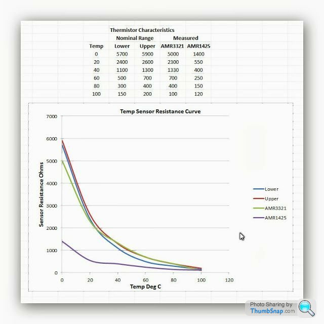
As you can see the resistance of AMR3321 is much greater at the useful / critical part of the temperature curve.
Out of curiosity I set up the old gauge with the sender and popped both into hot water (80 degrees) the gauge read well up the scale.
Completely off-topic but not unrelated...
I had serious hot-running problems last summer, even in January (UK) the bl**dy thing would need fans running after a few minutes in traffic.
The cooling system was classic RR radiator with two electric fans sucking.
The fans are wired series/parallel and triggered by one of those X-Eng adaptors in the bottom hose. I changed the sensor for a very cool one so half speed would happen earlier (standard sensor has two contacts. One switches at 88/83C and the other 92/87C).
Perhaps I've been over-reacting and the temperature gauge has been lying all along?
Things should be a lot cooler now - as part of the refit I ditched the brass original style radiator for an aluminium one.
100SRV
Edited by 100SRV on Tuesday 14th October 16:35
Gassing Station | Engines & Drivetrain | Top of Page | What's New | My Stuff