TVR 3000S Heater System Photos w/Triple Weber Carb Setup?
Discussion


Hello,
At some point the previous owner disconnected the car heater system on the 3000S. A piece on the water pump is missing and appears to have been plugged, when the system was disconnected.
The intake manifold has a triple weber carb setup, and has only one hole in the water jacket (besides the main water line to the radiator), in which the water temp sensor sending unit is currently inserted. Can someone provide pictures of a complete and properly setup heating system should like for a triple carb setup on the Essex V6? All of the rest of the unit appears to be there, heater box, the heater coil, heater fan, intake and exhaust hoses. Hose to the water pump missing as well as the piece off the water pump itself, some sort of steel plate plug and gasket bolted on the water pump. And no hose from the other inlet on the heater core going to the intake manifold. Anyone have a photo of the piece of the water pump that is no longer there? Thank you.
Hi Adrian,
Thank you for the information, but I will have to have another look at the rear of the water pump, I have had one good look and could not find any kind of outlet or plugged piece on the unit, just the blanked piece. Would you have a photo of where that outlet should be at the back of the water pump? Thanks.
Thank you for the information, but I will have to have another look at the rear of the water pump, I have had one good look and could not find any kind of outlet or plugged piece on the unit, just the blanked piece. Would you have a photo of where that outlet should be at the back of the water pump? Thanks.
Hi Adrian,
Fantastic, thank you. That explains a lot, my water pump does not have a 5/8 piece coming off the bottom of the inlet. I have just the main inlet. In going through the one of the previous owners paperwork, there is correspondence regarding the engine overheating, and that the system was disconnected. But, while I would have thought using the heater matrix would help cool the engine, it might not if the engine was plumbed incorrectly from the get go, if the 5/8 connector is not even there to begin with.
Sorry to be a bother, but I suspect the upper portion under the thermostat may not be there either, would you happen to have a photo of what that inlet looks like. I have been scratching my head, as I have read your earlier posts on this very subject, but if I cannot find the inlets, its pretty hard to figure it out. The car was owned by a car dealer at one time and I think several modifications were made. Maybe not all correct ones, at least to run the heater.
Hi Adrian,
I have photos, unfortunately, I have to find a way to shrink the bites to make it fit the forum. It would be much easier to show you, but my setup looks just like the one in given as an example in an earlier question a couple of years ago, 2010 maybe. It is the one in which just below the main inlet directly facing the fan is where the water temp sending unit was tapped in and inserted, and just to the left where my current temp sender unit is located, was the heater hose connection was made. My intake manifold looks nothing like one in the photo, and has not the heater hose connection inlet as yours shows. I will try to shrink the photos tonight and send smaller sized photo files if I can.
Since my water pump does not have the inlet setup, would the water pump section (part) you show in your photo part you indicate fit my water pump, or do I have some sort of different animal?
Hi Adrian,
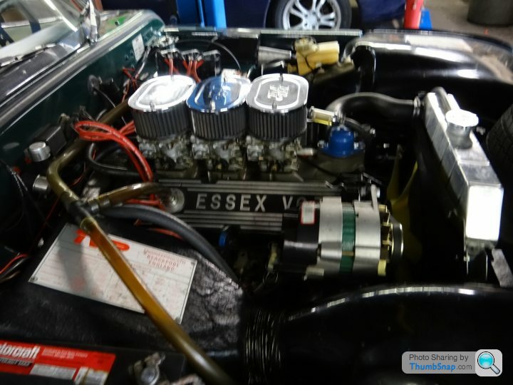
Most of photos are very dark, not as close up as I wanted. But the first photo shows the actual engine, and there is only one inlet on the manifold besides the main water line to the radiator, and that is where the water temp sending unit is screwed in just below the thermostat and radiator intake. There are no other inlet holes. If you look at the second photo, borrowed from Burton's page, it shows the 3.0L V6 engine setup with the intake manifold having two inlet holes just below the thermostat in radiator intake, one on the left for the heater, and one on the right for the temp sending unit.
So, is my only option to drill the second hole in the intake manifold in the same spot where it is missing on mine, and tap it for a 1/2" (5/8" too large)barbed hose adaptor? Or is there another option?
Completed heater matrix isolation and bypass on the 3000s. Spliced into the 5/8" ID hose from the intake manifold going to the water pump, with a 5/8" ID barbed T fitting. Ran a small piece of 5/8" hose to 5/8" barbed/1/2 MIP fitting into a 1/2" MIP T fitting. Off of this 1/2" T fitting is a 1/2" heater control valve with a 1/2" barb/FIP with a 1/2" ID heater hose to the top of the heater matrix intake (valve flow going to the matrix). Out of the other end of the same 1/2 T fitting, is 1/2" Barbed/MIP fitting to a 1/2" ID hose, leading to another 1/2" heater control valve, with two 1/2" barbed/FIP on each end of the valve to act as shut off of the 1/2" ID bypass hose (valve flow is toward the water pump). The other end of the bypass heater control valve is a 1/2" ID hose that goes to another 1/2" T fitting, with two of the ends having 1/2" barbed/MIP hose fittings. The third part of the T goes to another 1/2" heater control valve with a 1/2" barbed/FIP fitting with a 1/2" ID hose going to the bottom of the heater matrix. (heater control valve flow is leaving the heater matrix). The final part of of the 1/2" T fitting goes to the water pump, that has three inlets (from radiator bottom, 5/8" inlet from the intake manifold, and a 1/2" inlet from the bottom of the heater matrix.
So, the engine has one 5/8" ID heater hose bypass that is tapped with the 5/8 to 1/2" reduction to go to act as another bypass hose. Off of the 1/2" bypass hose are the two T fittings, one at each end of the heater matrix. Each T fitting has the 1/2" heater control valve to turn off/on to activate or isolate the heater matrix. A third heater control valve is in between the two T fittings at the heater matrix inlet and outlet. This third valve is turned off, when the two valves at the heater matrix are turned on. This forces more hot water through the matrix. And when the two valves at the heater matrix are both turned off, the bypass control valve in between the two is turned on, to activate the bypass, and isolate the heater matrix. Cool in summer, hot in winter. So far it is working great, no engine over heating, no leaks. But, I am in the process of upgrading the 1/2" ID heater hose to a SS outer braided with a rubber inner hose to act as a heat shield and to provide a more rigid hose that minimizes kinking and pinching, as it is in a very tight space very near the exhaust headers. Sorry for being so long winded confusion. But think I am ready for the professional plumbers exam.
So, the engine has one 5/8" ID heater hose bypass that is tapped with the 5/8 to 1/2" reduction to go to act as another bypass hose. Off of the 1/2" bypass hose are the two T fittings, one at each end of the heater matrix. Each T fitting has the 1/2" heater control valve to turn off/on to activate or isolate the heater matrix. A third heater control valve is in between the two T fittings at the heater matrix inlet and outlet. This third valve is turned off, when the two valves at the heater matrix are turned on. This forces more hot water through the matrix. And when the two valves at the heater matrix are both turned off, the bypass control valve in between the two is turned on, to activate the bypass, and isolate the heater matrix. Cool in summer, hot in winter. So far it is working great, no engine over heating, no leaks. But, I am in the process of upgrading the 1/2" ID heater hose to a SS outer braided with a rubber inner hose to act as a heat shield and to provide a more rigid hose that minimizes kinking and pinching, as it is in a very tight space very near the exhaust headers. Sorry for being so long winded confusion. But think I am ready for the professional plumbers exam.
Edited by SquashedCat on Thursday 23 July 05:26
Thank you to all of the people who have posted diagrams of how systems work on the TVR's, because you saved me hours of grief, as I originally dry fitted all of this plumbing literally backwards, it was when I went back and doubled checked a cooling system diagram and water flow pattern for the engine, did I realize I had dry fitted the system incorrectly, and was able to correct my error before the final assembly. Again, my most humble appreciation for your efforts.
Gassing Station | TVR Classics | Top of Page | What's New | My Stuff