Fitting a hall effect speedo sensor
Discussion


Hi,
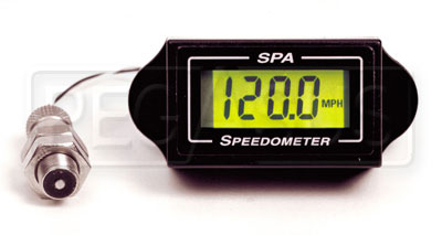
I want to fit one of these:
http://www.spa-uk.co.uk/design/speedo.asp
to my roadgoing Evo.
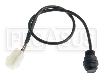
Apparently it comes with a sensor and magnet. I've been told that the magnet needs to be attached to "any rotational part of the drive train that generally moves at wheel speed with the exception of the prop shaft."
The unit is then calibrated by entering the rolling circumference of a wheel in mm.
My question is:
What is the best/normal place to mount these to a production front transverse engined, 4WD saloon car?
(I plan to climb under the car at the weekend to have a look for likely locations but I'd like someone to give me a hint as to where to start looking.
Cheers.
I want to fit one of these:
http://www.spa-uk.co.uk/design/speedo.asp
to my roadgoing Evo.
Apparently it comes with a sensor and magnet. I've been told that the magnet needs to be attached to "any rotational part of the drive train that generally moves at wheel speed with the exception of the prop shaft."
The unit is then calibrated by entering the rolling circumference of a wheel in mm.
My question is:
What is the best/normal place to mount these to a production front transverse engined, 4WD saloon car?
(I plan to climb under the car at the weekend to have a look for likely locations but I'd like someone to give me a hint as to where to start looking.
Cheers.
When it says not the prop shaft it is referring to the shaft to the rear diff. which will not be running at wheel speed. Your front or rear drive shafts should be OK. My choice would be the rear as these things don’t like electrical noise which will be far worse up amongst the engine workings.
The link does not show a pic of the magnet so advising how to fit it is somewhat difficult. Can you post a pic or different link?
Fitting to an inner CV/UJ joint ring of bolts would be ideal as the sensor can then be bracketed to the diff which stays still as opposed to the hub carrier which is moving with the suspension.
Steve
This is what I did with my kit car:
http://aeon.tribbeck.com/86/
Magnets got stuck to bolts holding disk, and I made a bracket for the sensor.
On my previous kit car, I glued the magnets to the outside of the drum, and made another bracket for it (but I didn't take any pictures of it). Of course, if the drum needed to be replaced, I'd need to get some more magnets...

I got their instructions for the dash they do yesterday as I'm considering it. The standard magnet with that is a small (doesn't specify size) disc magnet to allow gaps between magnet and sensor of between 2-5mm, with other magnets available allowing up to 18mm gaps.
It also says:
It also says:
SPA said:
If the target is running at wheel RPM then simply enter the tyre circumference as described above. However if the target is driving a differential, then using a calculator, divide the circumference of the tyre by the ratio of the differential, and enter this value as the circumference, as described at the beginning of this section.
Gassing Station | Engines & Drivetrain | Top of Page | What's New | My Stuff