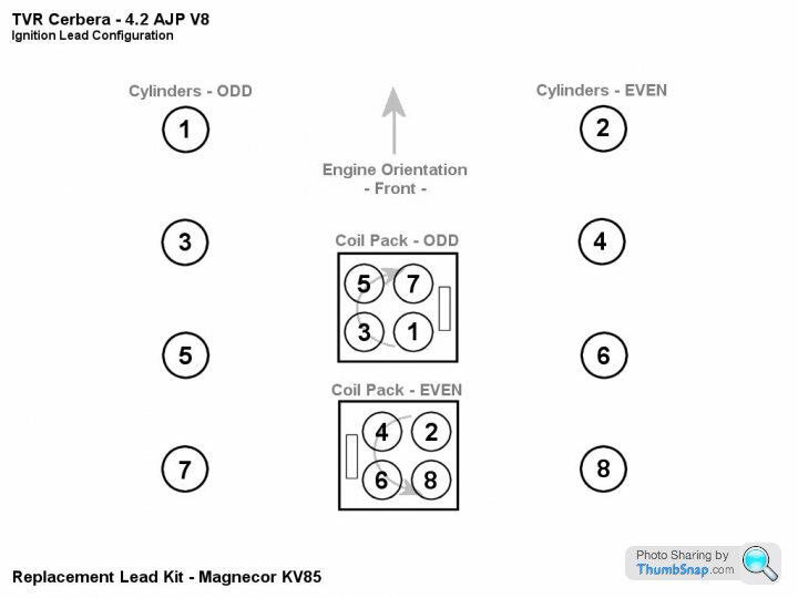
AJP Firing order

AJP Firing order

Author
Discussion

g20v6

Original Poster:

118 posts

204 months

Friday 20th February 2009
quotequote all
Can one of you helpful chaps tell me the correct cylinder firing order on the ajp please.

Many thanks Simon

JensenA

5,671 posts

231 months

Saturday 21st February 2009
quotequote all
Take a look here.....

Firing Order

Tony69

51 posts

183 months

Monday 4th May 2009
quotequote all
I have attached an image detailing the ignition lead layout/firing order for you.

From the recent work I did on my Cerbera - 1997 4.2 AJP v8

regards

Tony.


jesfirth

1,743 posts

243 months

Friday 10th July 2009
quotequote all
thanks guys - the leads are on correctly so why after I moved the frigging coil packs is the engine now running rough and the odd bank coil pack overheating and literally smoking within 30 seconds of firing up the engine?

methodwares

583 posts

245 months

Saturday 11th July 2009
quotequote all
Sounds like an internal short. Is the 'feed' connector on backwards?

M3John

5,974 posts

220 months

Tuesday 3rd August 2010
quotequote all
Hi guys, bit of a thread resurrection i know but was just wondering (well assuming actually) that this firing order is the same for a 4.5? I can't see any reason as to why it should be different.

M3J. smile

Rawhide

964 posts

214 months

Monday 23rd January 2012
quotequote all
Bounce. Does anyone know the firing order of a 4.5?

Jimii

182 posts

178 months

Monday 23rd January 2012
quotequote all
Same as above mate

SporttiJanne

112 posts

152 months

Monday 6th February 2012
quotequote all
I cannot figure out the firing order from the picture above.

So, which one it is? 1-6-3-2-7-4-5-8 or 1-4-5-2-7-6-3-8 ?

Jimii

182 posts

178 months

Tuesday 7th February 2012
quotequote all
edit i actually have no idea laugh

Edited by Jimii on Tuesday 7th February 10:13

tvrgit

8,472 posts

253 months

Tuesday 7th February 2012
quotequote all
SporttiJanne said:
I cannot figure out the firing order from the picture above.

So, which one it is? 1-6-3-2-7-4-5-8 or 1-4-5-2-7-6-3-8 ?
I don't know what the order is, but if Tony's diagram above is correct, then it can't be either of those two. Tony's diagram suggests that the firing order for the left bank is 1-3-5-7, and for the right bank, 2-4-6-8. Neither of those two you've quoted have either bank firing in the right order.


pacman1

7,322 posts

194 months

Tuesday 7th February 2012
quotequote all
I'm none the wiser, but now understand which numbers are odd and which are even! hehe

Tanguero

4,535 posts

202 months

Tuesday 7th February 2012
quotequote all
The diagram is (possibly!) nothing to do with he firing order. It is just the position of the plug leads on the coils.

ETA Uncertainty in view of later comments

Edited by Tanguero on Tuesday 7th February 11:49

tvrgit

8,472 posts

253 months

Tuesday 7th February 2012
quotequote all
Tanguero said:
The diagram is nothing to do with he firing order. It is just the position of the plug leads on the coils.
Am I being misled by the arrows showing direction of rotation (although I know there's no rotor arm!) that suggest a sequence for each coil?

Tanguero

4,535 posts

202 months

Tuesday 7th February 2012
quotequote all
tvrgit said:
Tanguero said:
The diagram is nothing to do with he firing order. It is just the position of the plug leads on the coils.
Am I being misled by the arrows showing direction of rotation (although I know there's no rotor arm!) that suggest a sequence for each coil?
Maybe I am misled too, but it looks to me simply that it shows the fitting order for the leads. I would not expect the firing sequence to be simply front to back on both banks, which is what the arrows would imply if that was what they indicated.

tvrgit

8,472 posts

253 months

Tuesday 7th February 2012
quotequote all
Tanguero said:
tvrgit said:
Tanguero said:
The diagram is nothing to do with he firing order. It is just the position of the plug leads on the coils.
Am I being misled by the arrows showing direction of rotation (although I know there's no rotor arm!) that suggest a sequence for each coil?
Maybe I am misled too, but it looks to me simply that it shows the fitting order for the leads. I would not expect the firing sequence to be simply front to back on both banks, which is what the arrows would imply if that was what they indicated.
I wouldn't normally expect that either, but that IS the firing order on a Ford V6, for example - left-right, front to rear both banks... so even though it doesn't make sense for a V8, my addled brain can't necessarily rule it out.

Mark.

11,104 posts

277 months

Tuesday 7th February 2012
quotequote all
tvrgit said:
Tanguero said:
tvrgit said:
Tanguero said:
The diagram is nothing to do with he firing order. It is just the position of the plug leads on the coils.
Am I being misled by the arrows showing direction of rotation (although I know there's no rotor arm!) that suggest a sequence for each coil?
Maybe I am misled too, but it looks to me simply that it shows the fitting order for the leads. I would not expect the firing sequence to be simply front to back on both banks, which is what the arrows would imply if that was what they indicated.
I wouldn't normally expect that either, but that IS the firing order on a Ford V6, for example - left-right, front to rear both banks... so even though it doesn't make sense for a V8, my addled brain can't necessarily rule it out.
It's not impossible, it could also be the reason they sound like the do. However, we are told the flat plane crank is effectively 2 straight 4's bolted together, so if you were to separate them, then individually, they couldn't run. But then they are not separated so......

Tanguero

4,535 posts

202 months

Tuesday 7th February 2012
quotequote all
tvrgit said:
Tanguero said:
tvrgit said:
Tanguero said:
The diagram is nothing to do with he firing order. It is just the position of the plug leads on the coils.
Am I being misled by the arrows showing direction of rotation (although I know there's no rotor arm!) that suggest a sequence for each coil?
Maybe I am misled too, but it looks to me simply that it shows the fitting order for the leads. I would not expect the firing sequence to be simply front to back on both banks, which is what the arrows would imply if that was what they indicated.
I wouldn't normally expect that either, but that IS the firing order on a Ford V6, for example - left-right, front to rear both banks... so even though it doesn't make sense for a V8, my addled brain can't necessarily rule it out.
While I can't be completely certain my recollection from the last time I had the covers of to do the valve clearances is that the order that the valves closed on the compression stroke, hence the firing order on a bank, was 1st-3rd-2nd-4th, which I guess would make the full order across banks something 1-2-5-6-3-4-7-8 however I don't know what the interbank timing is.

SporttiJanne

112 posts

152 months

Tuesday 7th February 2012
quotequote all
The picture above seems to be about fitting the plug leads, nothing to do with the actual firing order.

According to this animation, the sequence cannot start 1-2-...
http://www.projectm71.com/Flatplane.gif

FarmyardPants

4,112 posts

219 months

Tuesday 7th February 2012
quotequote all
Looking at the right bank, 6 can't follow 4, they are on the same but of the crank.

I would expect the even order to be something like 2,4,8,6 (ie up,down,up,down as you look at the pistons in the bores) and similarly 1,3,7,5 for the odd bank