Getting the most out of the Throttle Bodies
Discussion


Just done quite a lot of work on this for my university dissertation. Designed and built a carbon fibre inlet manifold for a formula sae car and designed (but didn't have time to build) a linear stepper motor controlled telescopic inlet primary system which took a signal from the crank sensor and via a pic PLC controller, sent the appropriate pipe height to the motor which would adjust very fast indeed.
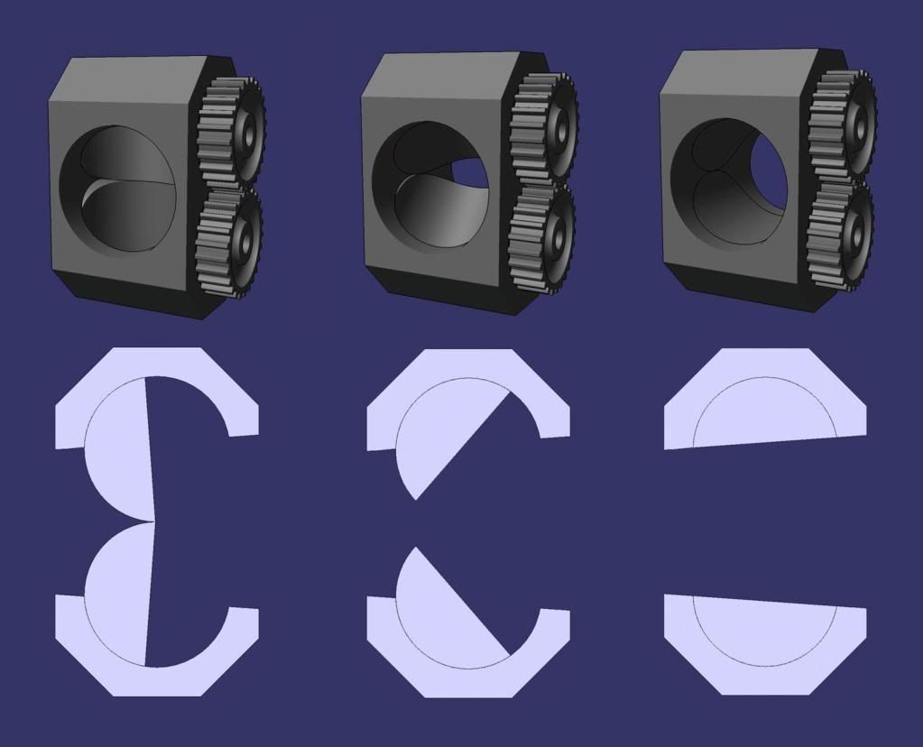
Anyhoo, as part of my research, I did a lot of work into throttle design and flow characteristics and I can safely say that a dual roller barrel system provides optimum flow. Camera shutter types cause some weird vorticies and are difficult to make strong enough, and butterflies create turbulance in the inlet...
What you want is something like this:
Following that, you want to get hold of a copy of this book: http://www.amazon.co.uk/Theory-Engine-Manifold-Des...
And this book: http://www.amazon.co.uk/INTERNAL-COMBUSTION-ENGINE...
Ok they are a little pricey, but I'm sure you can get them somewhere cheaper on the net! I had to use the uni library copies... Both have some very good info on intake manifold design and theory though including variable length systems, exhaust gas recovery, dual plenum designs with balance valves, acoustic ramming, helmholtz resonators and all sorts... Interesting reading!
Edited by 450Nick on Friday 15th May 21:03
spitfire4v8 said:
hmm .. injecting something oxygen-rich would be good, allow you to burn more fuel .. I wonder if such a system exists 
I thought that Nos worked more on the priciple that it rapidly cools (and therefore makes more dense) the air entering the cylinders? Hence why drag cars run purge systems to make sure that the Nos is as cool as it can be when it leaves the pipe...
While I applaud staying with the original configuration, you've go to look at bike throttle bodies.
You can find the vtl (variable tract length) on this years R1 and also on the MV Augusta from last year..
Though honestly without cramming the air in I think you are up against the wall due to the inlet valve size.
You can find the vtl (variable tract length) on this years R1 and also on the MV Augusta from last year..
Though honestly without cramming the air in I think you are up against the wall due to the inlet valve size.
I'm very tempted to buy the two books you have recommended Nick450, but I fear if I did then I'd sit down for six months reading and not move a muscle in that time. 
Correct me on general theory here.
The wider the pipe, the slower the flow and the higher the pressure.
As the pipe narrows the flow speed increases, the pressure decreases, the frictional forces at the side walls increase, and the boundary layer increases.
Total energy of flow decreases proportionally to the flow speed, by speed^2?.
If the above is right, and on flow characteristics only, why are all inlet tracts a steady decrease throughout their whole length, and not wide open till the last part of the head before the valve, when the conversion from slow and high, to fast and low just before the valve loses the least amount of flow energy in frictional forces, and has the advantage of not running the flow fast past the butterfly obstructions.
julian64 said:
I'm very tempted to buy the two books you have recommended Nick450, but I fear if I did then I'd sit down for six months reading and not move a muscle in that time.
Correct me on general theory here.
The wider the pipe, the slower the flow and the higher the pressure.
As the pipe narrows the flow speed increases, the pressure decreases, the frictional forces at the side walls increase, and the boundary layer increases.
Total energy of flow decreases proportionally to the flow speed, by speed^2?.
If the above is right, and on flow characteristics only, why are all inlet tracts a steady decrease throughout their whole length, and not wide open till the last part of the head before the valve, when the conversion from slow and high, to fast and low just before the valve loses the least amount of flow energy in frictional forces, and has the advantage of not running the flow fast past the butterfly obstructions.
True, there is rather a lot to read, but there is a lot of useful stuff in there.Correct me on general theory here.
The wider the pipe, the slower the flow and the higher the pressure.
As the pipe narrows the flow speed increases, the pressure decreases, the frictional forces at the side walls increase, and the boundary layer increases.
Total energy of flow decreases proportionally to the flow speed, by speed^2?.
If the above is right, and on flow characteristics only, why are all inlet tracts a steady decrease throughout their whole length, and not wide open till the last part of the head before the valve, when the conversion from slow and high, to fast and low just before the valve loses the least amount of flow energy in frictional forces, and has the advantage of not running the flow fast past the butterfly obstructions.
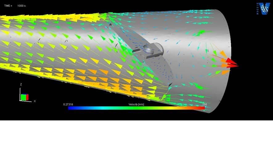
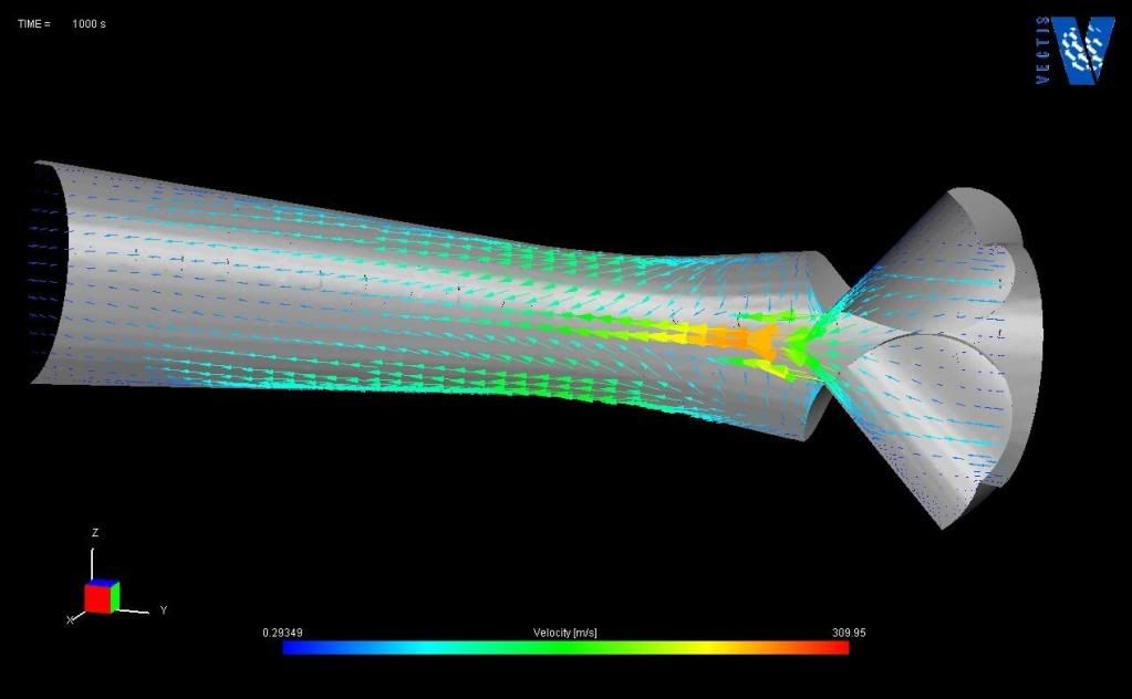
With regard to the pipe theory, with an injection engine, you want as little wall friction as possible (this is desirable in carburetted engines though), so smoothness is key to keep outright gas speed high. Diameter as you say affects the gas momentum quite a bit; it chokes the engine if its too small and slows response if too big. There are a few formulas around to work out the optimum for your engine, one is listed here: http://books.google.co.uk/books?id=ze_w0i3xZmAC&am... on page 120, there are better (metric) ones listed in books such as listed above. Also as you say, a pipe taper is often seen; this is to air cylinder filling by gently upping the gas speed immediatly prior to the valve. That link above also details the optimum pipe taper at around 1.7-2.5 degrees.
There are also a few theories to calculate optimum runner length for acoustic resonance at a particular revs. This basically means that as the valve shuts, fast moving air hits the back of the valve and a pressure wave is sent back up the inlet pipe at the speed of sound (local to that air temperature). As this pressure wave meets the open end in the plenum, it is reflected as a rarefaction wave back down the pipe. If the valve is still shut, it will bounce back and forth, diminishing in size. If the valve is open though, it will force a small amount of extra air into the cylinder. The idea is to time this reflected wave to force some extra air into the cylinder just before the valve shuts on the next stroke, producing a mild supercharging effect. This will only happen at a particular engine speed dependant on the length the wave has to travel (primary pipe length) and the speed of the wave (air temp and pipe diameter). One of the theories to calculate this is listed in that book shown above:
L = [(ECD x 0.25 x V x 2) / (rpm x RV)] - (D / 2)
Where:
L = primary length
ECD = Effective cam duration
V = Local speed of sound
rpm = resonant engine speed
RV = Reflective value (1 for first reflection used, 2 for 2nd reflection etc)
D = primary diameter
This can be written into an Excel spreadsheet pretty easily so that you can play with the variables and see how long the inlet needs to be for different engine speeds when choosing.
Edited by 450Nick on Saturday 16th May 12:54
julian64 said:
As the pipe narrows the flow speed increases, the pressure decreases, the frictional forces at the side walls increase, and the boundary layer increases.
If you have smooth flow in the pipe, a boundary layer will accumulate as the air moves down the pipe. In this context the boundary is bad news because it (slightly) reduces the area of air that is moving and also makes the flow more likely to separate at any corner or irregularity. Reducing the section will have the effect of accelerating the air, the boundary layer is accelerated along with everything else. This 're-energises' the boundary layer making the flow less likely to separate.
I'm probably going to make myself look a righ muppet but it might be worth investigating the following.
It's also worth investigating riblets: http://www.informaworld.com/smpp/content~content=a...
Imagine the surface of the throttle body is stationary. As the air molecules slide over this stationary surface they will start to roll, causing lateral rolling vortices. By scoring the surface with microscopic longitudinal groves, these vortices are 'chopped' before they fully form, thus reducing drag.
Some say this is why shark skin is rough with longitidunal grooves. This technology has been used in heat exchangers and the bodies of fast moving underwater objects: I'll let you guess what.
In theory, the last thing you want to do is polish the bore.
If someone who knows what they are talking about would like to shoot me down in flames, feel free.
Hmm, okay. Nick do you have any links to the reasons how the taper is calculated as optimum and why. In other worde why a continuous taper is better than sudden taper at the end.
Reason I ask is this.
The inlet to the throttle is 45mm, making an area air can flow through.
Unfortunately the 45 mm diameter is impeded by a 10mm spindle bar.
That gives a flow area of pi*22.5^2 - 10*45 = 1140mm2
Down at the outlet of the throttle body and into the head the pipe has narrowed to 40mm but there is no spindle
so the area is now pi*20^2 = 1256mm2
If I have my sums right then the flow is slowing after the throttle body not speeding up as it should. In fact the flow is fast past the throttle body, slows down on its way into the head, and then speeds up past the valve. This can't be optimum.
back calculating and ignoring the obvious turbulence caused by the spindle you would have to thin the spindle to a maximum of 7.4 mm even to maintain the same area, and at that point there would be no flow increase right the way down to a sudden acceleration at the valve.
If a taper is desirable beacuse a gradual increase in flow until the valve head is important, then the current throttle body misses by a mile.
Thining your spindle to 7.4 mm is only the equivalent of a completely non tapered system. You might as well have a cylinder there?
If you have links to why a 2.5 taper is best then maybe the next step is to work out how to minimise the spindle and butterfly turbulence but as a seperate issue renew the taper in real terms by opening out the top. I get the impression that bigger butterflies seem to be able to justify themselves purely on the basis of the current inlet size without having to mess with the head to justify increasing them?
I thought the 4.5 butterfly was 46mm and the 4.2 was 44mm  . If correct that's not a massive difference in terms of csa; 1661 vs 1521 obv without spindle/butterfly. My ported 4.2 set up flows enough for 450hp in my car and probably enough for 470hp too. It's inherently shorter in length and should assist higher up the band too, the injector is below the butterfly and allows near direct injection onto the back of the valve, the butterfly is further away and allows re-stabilisation of the air flow. I wouldn't dismiss the 4.2 set up out of hand tbh, the Boss cerb uses this set up, although the numbers might have been tvr ponies the thinking was considered and sound imho.
A snippet I got straight from the horses mouth (David Vizard when at Austec) A Rule of thumb is that properly gas flowing an existing set up gives about 5x the gain as just going up a size. The spindle on either set up can effectively be half its current csa with working, knife edging the leading and trailing edges of the butterfly will help a fair bit too.
If it wasn't such a fag I'd offer to let you do back to back testing with my intakes on your lump, but the time you factor in the completely different maps and injectors it's not a small job.
. If correct that's not a massive difference in terms of csa; 1661 vs 1521 obv without spindle/butterfly. My ported 4.2 set up flows enough for 450hp in my car and probably enough for 470hp too. It's inherently shorter in length and should assist higher up the band too, the injector is below the butterfly and allows near direct injection onto the back of the valve, the butterfly is further away and allows re-stabilisation of the air flow. I wouldn't dismiss the 4.2 set up out of hand tbh, the Boss cerb uses this set up, although the numbers might have been tvr ponies the thinking was considered and sound imho.A snippet I got straight from the horses mouth (David Vizard when at Austec) A Rule of thumb is that properly gas flowing an existing set up gives about 5x the gain as just going up a size. The spindle on either set up can effectively be half its current csa with working, knife edging the leading and trailing edges of the butterfly will help a fair bit too.
If it wasn't such a fag I'd offer to let you do back to back testing with my intakes on your lump, but the time you factor in the completely different maps and injectors it's not a small job.
HarryW said:
I thought the 4.5 butterfly was 46mm and the 4.2 was 44mm . If correct that's not a massive difference in terms of csa; 1661 vs 1521 obv without spindle/butterfly. My ported 4.2 set up flows enough for 450hp in my car and probably enough for 470hp too. It's inherently shorter in length and should assist higher up the band too, the injector is below the butterfly and allows near direct injection onto the back of the valve, the butterfly is further away and allows re-stabilisation of the air flow. I wouldn't dismiss the 4.2 set up out of hand tbh, the Boss cerb uses this set up, although the numbers might have been tvr ponies the thinking was considered and sound imho.
A snippet I got straight from the horses mouth (David Vizard when at Austec) A Rule of thumb is that properly gas flowing an existing set up gives about 5x the gain as just going up a size. The spindle on either set up can effectively be half its current csa with working, knife edging the leading and trailing edges of the butterfly will help a fair bit too.
If it wasn't such a fag I'd offer to let you do back to back testing with my intakes on your lump, but the time you factor in the completely different maps and injectors it's not a small job.
Harry, the inlet on my 4.2 tapers down at the top, but at the head end its 36mm diameter going into a 40mm head. While theres lots of meat on the head there is virtually none on the end of the 4.2. Other than that I'd love to have used it for all the reasons you've said. Machining it any bigger would be a flexible hone and crossed fingers.. If correct that's not a massive difference in terms of csa; 1661 vs 1521 obv without spindle/butterfly. My ported 4.2 set up flows enough for 450hp in my car and probably enough for 470hp too. It's inherently shorter in length and should assist higher up the band too, the injector is below the butterfly and allows near direct injection onto the back of the valve, the butterfly is further away and allows re-stabilisation of the air flow. I wouldn't dismiss the 4.2 set up out of hand tbh, the Boss cerb uses this set up, although the numbers might have been tvr ponies the thinking was considered and sound imho.A snippet I got straight from the horses mouth (David Vizard when at Austec) A Rule of thumb is that properly gas flowing an existing set up gives about 5x the gain as just going up a size. The spindle on either set up can effectively be half its current csa with working, knife edging the leading and trailing edges of the butterfly will help a fair bit too.
If it wasn't such a fag I'd offer to let you do back to back testing with my intakes on your lump, but the time you factor in the completely different maps and injectors it's not a small job.
On the other hand the 4.5 inlet is 50 at the top without the guide for the inlet hose, and plenty of meat, maybe even another 4-5 mm diameter. The head end is 40 to match the head, but if the head came further out the 4.5 inlet could match it with the meat. Add to that the 4.5 inlet is a straight through machining job that I think could be donw with a boring tool almost straight.
I'm afraid its a clear winner

julian64 said:
HarryW said:
I thought the 4.5 butterfly was 46mm and the 4.2 was 44mm . If correct that's not a massive difference in terms of csa; 1661 vs 1521 obv without spindle/butterfly. My ported 4.2 set up flows enough for 450hp in my car and probably enough for 470hp too. It's inherently shorter in length and should assist higher up the band too, the injector is below the butterfly and allows near direct injection onto the back of the valve, the butterfly is further away and allows re-stabilisation of the air flow. I wouldn't dismiss the 4.2 set up out of hand tbh, the Boss cerb uses this set up, although the numbers might have been tvr ponies the thinking was considered and sound imho.
A snippet I got straight from the horses mouth (David Vizard when at Austec) A Rule of thumb is that properly gas flowing an existing set up gives about 5x the gain as just going up a size. The spindle on either set up can effectively be half its current csa with working, knife edging the leading and trailing edges of the butterfly will help a fair bit too.
If it wasn't such a fag I'd offer to let you do back to back testing with my intakes on your lump, but the time you factor in the completely different maps and injectors it's not a small job.
Harry, the inlet on my 4.2 tapers down at the top, but at the head end its 36mm diameter going into a 40mm head. While theres lots of meat on the head there is virtually none on the end of the 4.2. Other than that I'd love to have used it for all the reasons you've said. Machining it any bigger would be a flexible hone and crossed fingers.. If correct that's not a massive difference in terms of csa; 1661 vs 1521 obv without spindle/butterfly. My ported 4.2 set up flows enough for 450hp in my car and probably enough for 470hp too. It's inherently shorter in length and should assist higher up the band too, the injector is below the butterfly and allows near direct injection onto the back of the valve, the butterfly is further away and allows re-stabilisation of the air flow. I wouldn't dismiss the 4.2 set up out of hand tbh, the Boss cerb uses this set up, although the numbers might have been tvr ponies the thinking was considered and sound imho.A snippet I got straight from the horses mouth (David Vizard when at Austec) A Rule of thumb is that properly gas flowing an existing set up gives about 5x the gain as just going up a size. The spindle on either set up can effectively be half its current csa with working, knife edging the leading and trailing edges of the butterfly will help a fair bit too.
If it wasn't such a fag I'd offer to let you do back to back testing with my intakes on your lump, but the time you factor in the completely different maps and injectors it's not a small job.
On the other hand the 4.5 inlet is 50 at the top without the guide for the inlet hose, and plenty of meat, maybe even another 4-5 mm diameter. The head end is 40 to match the head, but if the head came further out the 4.5 inlet could match it with the meat. Add to that the 4.5 inlet is a straight through machining job that I think could be donw with a boring tool almost straight.
I'm afraid its a clear winner
That said the set I have now have limited work at the top near at the bend and standard size 4.2 butterflys still, obviously the bottoms now line up properly with the heads at 40mm too, lots of work on the butterlys and spindles and bobs your mothers brother, do not dismiss them.
I had a third idea today which is so radical its pretty much starting from scratch.
There is a vaccum chamber which runs along the length of the 4.5 inlets. It has a small hole going into each throttle body below the butterfly. It works as an addition of all the inlets vaccum and transfers it to a tube at one end of the rail. In addition a second vaccum is taken simply from the first throttle body.
As all I've been doing today is staring at inlets while I refurbed the burnt out one I had, a cunning plan came to me.
Although there isn't enough space for rollerbody design in the 4.5 inlets because of their spacing, there is a cunning way of sorting it if you cut the spindle connection between each throttle body. Junk the vaccum chamber, and bore the vaccum chamber for a spindle to operate each throttle body seperately via a linkage.
In this way you've just made youself a big degree of space, and I think I can get a zero cross section system working off this.
Because I'm just looking at the throttle bodies in isolation, can anyone tell me the reason for the two types of vaccum pickoff, and the possibility of relocating them??
julian64 said:
I had a third idea today which is so radical its pretty much starting from scratch.
There is a vaccum chamber which runs along the length of the 4.5 inlets. It has a small hole going into each throttle body below the butterfly. It works as an addition of all the inlets vaccum and transfers it to a tube at one end of the rail. In addition a second vaccum is taken simply from the first throttle body.
As all I've been doing today is staring at inlets while I refurbed the burnt out one I had, a cunning plan came to me.
Although there isn't enough space for rollerbody design in the 4.5 inlets because of their spacing, there is a cunning way of sorting it if you cut the spindle connection between each throttle body. Junk the vaccum chamber, and bore the vaccum chamber for a spindle to operate each throttle body seperately via a linkage.
In this way you've just made youself a big degree of space, and I think I can get a zero cross section system working off this.
Because I'm just looking at the throttle bodies in isolation, can anyone tell me the reason for the two types of vaccum pickoff, and the possibility of relocating them??
I'm liking this!!There is a vaccum chamber which runs along the length of the 4.5 inlets. It has a small hole going into each throttle body below the butterfly. It works as an addition of all the inlets vaccum and transfers it to a tube at one end of the rail. In addition a second vaccum is taken simply from the first throttle body.
As all I've been doing today is staring at inlets while I refurbed the burnt out one I had, a cunning plan came to me.
Although there isn't enough space for rollerbody design in the 4.5 inlets because of their spacing, there is a cunning way of sorting it if you cut the spindle connection between each throttle body. Junk the vaccum chamber, and bore the vaccum chamber for a spindle to operate each throttle body seperately via a linkage.
In this way you've just made youself a big degree of space, and I think I can get a zero cross section system working off this.
Because I'm just looking at the throttle bodies in isolation, can anyone tell me the reason for the two types of vaccum pickoff, and the possibility of relocating them??
We really do need a scrap set of bodies!
Gassing Station | Cerbera | Top of Page | What's New | My Stuff