Rear upright and lower rear arm not correct to top arm..??
Discussion


Well... Got all the rear arms in nice and sorted with their Powerflex etc.... put the Passengers side upright on (thought it would be a fight but straight on!)and it fell in line with the nip on the upper arm no problem...
Then put the driver’s side upright in and it's all one way in the nip towards to front of the car... You can tug it and you can get it half way (or in the centre) of the nip... But I don't want to load the Powerflex like this... So started to look for reasons....
.
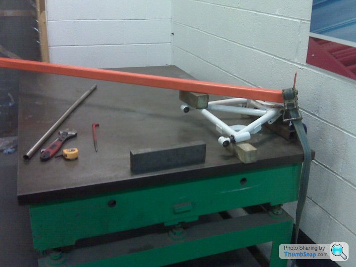
On sighting up the passenger side bottom arm, I noticed the outer tube where the upright and shocker lower goes runs flat with the rear tube at the back where the bushes go....
But on the drivers side, these two tubes run out a bit, making the front tube about 2mm lower to the forward end... so therefore throwing out the upright when fitted so the top of this is more towards the front than you get on the passenger side...
.
Now I'm sure this is all in manufacturing tolerance and some folk would just prize it together and clamp it up... but this will side load the Powerflex and may lead to them failing... I'm sure with the old rubber bush units this would not be so much of a problem as they may have moved easier to overcome slight misalignment....
.
Has anyone else had this issue?.. I know it's not the top arms as I spent last weekend getting them cock on to each other... and swapping them over does not make any difference... also the Chassis measures up okay and its not twisted or anything.. so guess it is the flatness of the lower arm.
.
So, off to make a jig now to twist it by a couple of 'mm' to get it right..
These arms have just been powder coated so could be the burn-off over has warped them or something??.. although I do remember looking at the thrust washers and the pattern they had made in the paint on the upright when I took it in bits, suggesting things were twisted then...
.
Great.. ever wish you'd not started a job !!
Then put the driver’s side upright in and it's all one way in the nip towards to front of the car... You can tug it and you can get it half way (or in the centre) of the nip... But I don't want to load the Powerflex like this... So started to look for reasons....
.
On sighting up the passenger side bottom arm, I noticed the outer tube where the upright and shocker lower goes runs flat with the rear tube at the back where the bushes go....
But on the drivers side, these two tubes run out a bit, making the front tube about 2mm lower to the forward end... so therefore throwing out the upright when fitted so the top of this is more towards the front than you get on the passenger side...
.
Now I'm sure this is all in manufacturing tolerance and some folk would just prize it together and clamp it up... but this will side load the Powerflex and may lead to them failing... I'm sure with the old rubber bush units this would not be so much of a problem as they may have moved easier to overcome slight misalignment....
.
Has anyone else had this issue?.. I know it's not the top arms as I spent last weekend getting them cock on to each other... and swapping them over does not make any difference... also the Chassis measures up okay and its not twisted or anything.. so guess it is the flatness of the lower arm.
.
So, off to make a jig now to twist it by a couple of 'mm' to get it right..
These arms have just been powder coated so could be the burn-off over has warped them or something??.. although I do remember looking at the thrust washers and the pattern they had made in the paint on the upright when I took it in bits, suggesting things were twisted then...
.
Great.. ever wish you'd not started a job !!
Yes (or to within 2mm of each other as I measured them and re-set them to where they were when they came off)... Anyway, this would tend to give an 'in-out' type movement with the bottom arm level.. what I'm seeing is more a tilt 'forwards-backwards' bit that we have no adjustment for....
Edited by TVR Beaver on Sunday 6th February 16:19
Mmmm will have a play I think... they look very solid so thats half the fun trying to tweek them
I also measured the end of the arms when straight out relative to a sheet of wood on the floor (not 100% accurate).. but confirmed what I thought... measuring both ends of the outer tube, the passenger side was 10mm higher at the front that the back (they do go up hill a tad and my stands are not the same hight so add to this).. where as the Drivers side only went up 6mm... so it needs the arm twisting...
Will be a handy jig to have....
.
How much was yours out in the nip one to the other??
Quinny said:
Yep..... When I did mine, I fitted the bottom adjuster to the chassis, without the wishbone that way I only had to get one lug to line up....
The last thing I fitted was the 19mm locknut, that goes inside the adjuster tube
Yup.. tried all that.. even filed the holes out on the four upright mounts to get the paint out etc.. that got me in the nip, but not in the right position... still more needed..... that way I only had to get one lug to line up....The last thing I fitted was the 19mm locknut, that goes inside the adjuster tube
Quinny said:
The passenger side one was "tipped" forwards and was touching the slotted hole on the top upright.......
The drivers side was the exact opposite and was tipped backwards and was touching the rear slotted hole on the upright..
All I did was force the spacers in and centre them..
The drivers side was the exact opposite and was tipped backwards and was touching the rear slotted hole on the upright..
All I did was force the spacers in and centre them..
yes... bet I've got the same.. I did open the top nip up last weekend to get the top arm faces parellel, so I've got about 6mm play in there... The drivers side hit's the slot at the front as your saying.. and the other side sits just off centre but the other way... so I guess about 4mm one side to the other... Just don't fance pulling it over and side loading them.... it would take a lot of force to do it.. and then thats in there for everI suppose if both of yours were out and you pulled them both into the centre, then the would be loaded equal amounts (all be it from different directions).. but I've just 1 out.. so it would give it loaded one side (3 to 4mm to move), but not the other...
And to twist it this much means the Poly bush would have to squish quite a lot on 1 side.. may be 1mm or so on the wall?... don't want tp dp that...
.
I agree I may be pratting about trying to get it right but I'm good at that... pratting about is my best pastime ...
I'll see if I can bend it tomorrow having made a jig... I've already turned up the mounts so just needs welding up.. It must be the lower arms that cause these issues on all out cars as the rest on mine measures up fine... at least we'll have a bending jig then and an answer as to wether the things can be 'set'.. if not... I'll hammers the spacers in and forget about it sure your right.. thats how the factory did it ...but not to say you can't improve on what they did (or so I'm finding!!)

And to twist it this much means the Poly bush would have to squish quite a lot on 1 side.. may be 1mm or so on the wall?... don't want tp dp that...
.
I agree I may be pratting about trying to get it right
but I'm good at that... pratting about is my best pastime ... I'll see if I can bend it tomorrow having made a jig... I've already turned up the mounts so just needs welding up.. It must be the lower arms that cause these issues on all out cars as the rest on mine measures up fine... at least we'll have a bending jig then and an answer as to wether the things can be 'set'.. if not... I'll hammers the spacers in and forget about it
sure your right.. thats how the factory did it ...but not to say you can't improve on what they did (or so I'm finding!!)It is common for these to be twisted IMHO welded/heat related pulling (even more common in earlier TVR's is torque twisted), and in my development of rear discs on the M series we found brake torque related twist ( which is VERY bad when combined could lead to breakages) I have a simple hook tool which draws through a hole in my welding table and I stack the wishbone on gauge blocks and pull the corner that is high down (over compensate and it springs back to a central position).
Adrian@
Adrian@
Yes.. thats the thing... I've made the two blocks with holes in that will go between the front upright mounts with bolts in and will weld these to two 50mm pillars... Choch the other corner with a wood block... and somehow pull / push the other corner... Sounds good to me... Let's see if I can make it work
Adrian... ever broken one?... They are very stiff ... just wondered if you could fracture one at all if you went too far?.....
.
Anyway.. problem sloved.... Bent about 4 mm from where it was and now bang in the middle of the nip so no need for side load....
I have the front holding fixture if anyone wants to use it (too heavy to post though)...
.

.
.
.
Anyway.. problem sloved.... Bent about 4 mm from where it was and now bang in the middle of the nip so no need for side load....
I have the front holding fixture if anyone wants to use it (too heavy to post though)...
.
.
.
Edited by TVR Beaver on Friday 11th February 07:34

TVR Beaver said:
Adrian... ever broken one?... They are very stiff ... just wondered if you could fracture one at all if you went too far?.....
No never broke one, you NEED to go past the point required to allow the changes to relax back to true...had to do corrective welding in the past, where the ARB bracket welding had left a main tube pin holed, and replaced a rotten tube (both as part of converting from Mk1 to Mk2 ARB brackets)..the design features evolve from 1971 M series so I've been playing with the this form of wishbone for 30 years.Adrian@
PS pretty jig ..if you want somewhere for it live and point peeps to me to loan it out from (FOC, but covering carriage of course)...
Yes... all done and in... It did appear to go at one point quite easy.. measureing the end being bent by putting a metal parallel in 114mm / 112mm / 110mm / 100mm!.. so bent it back 100mm to 111mm... But sure it can't of done... I'think I must have measured it wrong at the time but gave me a fright.. may be not changed the wooden block for the parallel or something ... I've also looked for bend points on the tubes and they are distributed along the tubes so no one area thats given out... so all happy with that now... and in the middle of the nip ..
I will do as you say in your previous post i.e. make washers to fit and centralise them (now I understand whats going on here and how stiff these things are)
You can have the jig if you want... I've no use for it now... Are you going the Chatsworth may be coz its heavy to post...
... I've also looked for bend points on the tubes and they are distributed along the tubes so no one area thats given out... so all happy with that now... and in the middle of the nip .. I will do as you say in your previous post i.e. make washers to fit and centralise them (now I understand whats going on here and how stiff these things are)
You can have the jig if you want... I've no use for it now... Are you going the Chatsworth may be coz its heavy to post...
Gassing Station | Griffith | Top of Page | What's New | My Stuff