Project Scimitar MV6
Discussion


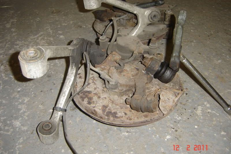
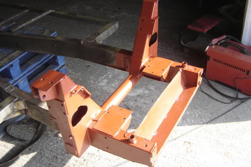
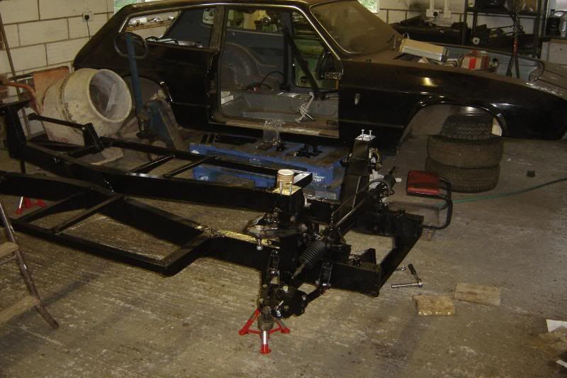
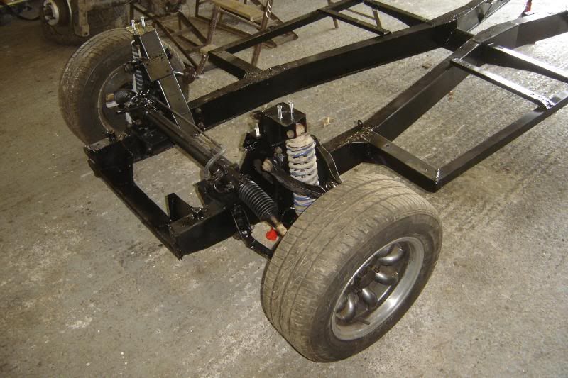
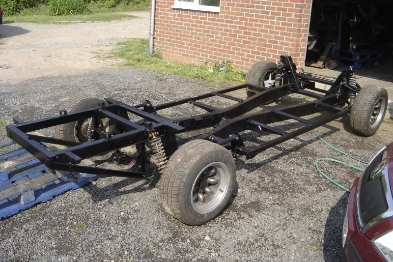
The car has had so many development, all new bigger brakes stolen from various ford and rover parts, AVO adjustable suspension, the bumpers are homemade, I tried my hand at spraying (I couldn't make a career of it). And the latest projects have been to remake the front trunion joint into a ball joint from a mkiii supra (far far stronger). And of course change all the rusty bits in the chassis for stainless.
So here's the progess on the recent projects lifted straight from the RSSOC forum.
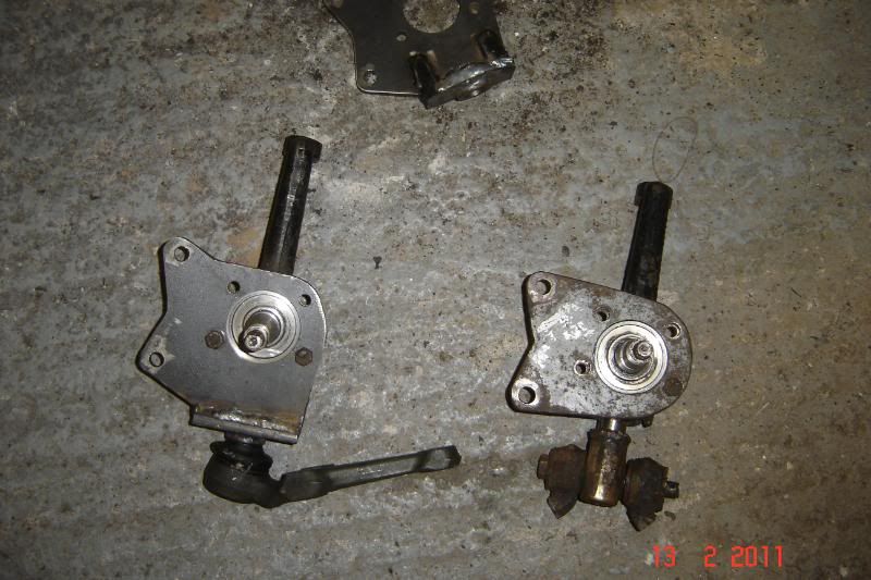
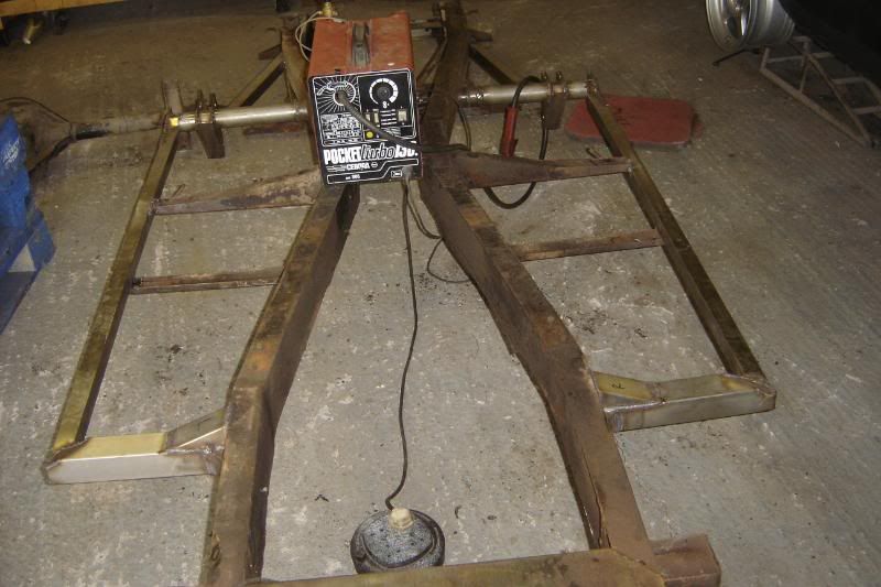
I had an idea, and it goes a bit like this.
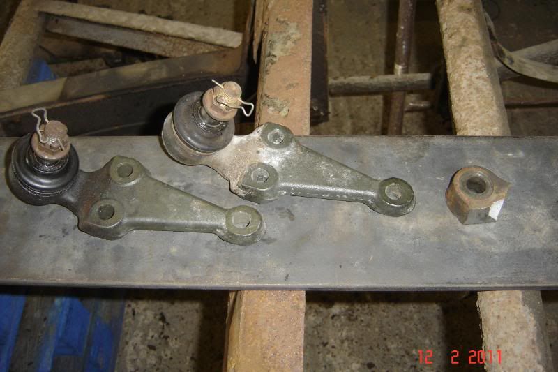
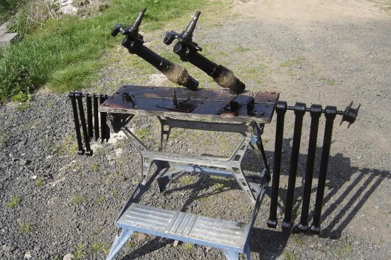
Had some old Supra bits lying around, they're strong! supra weighs 1600kg
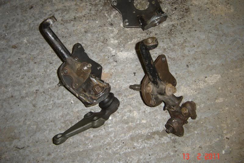
Choppy Choppy
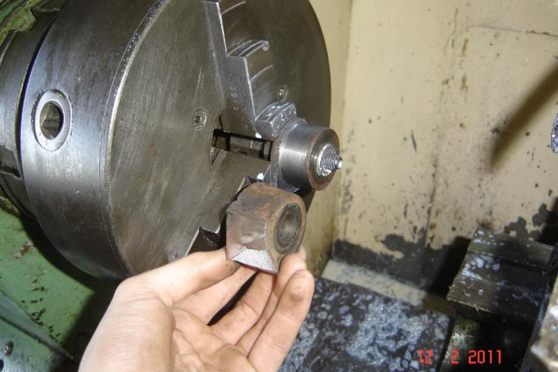
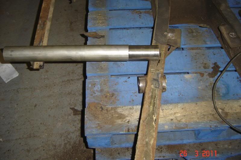
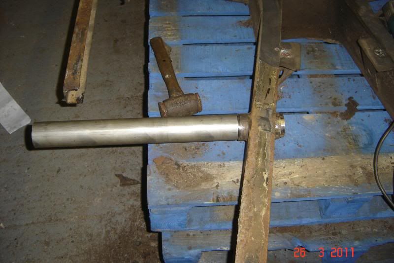
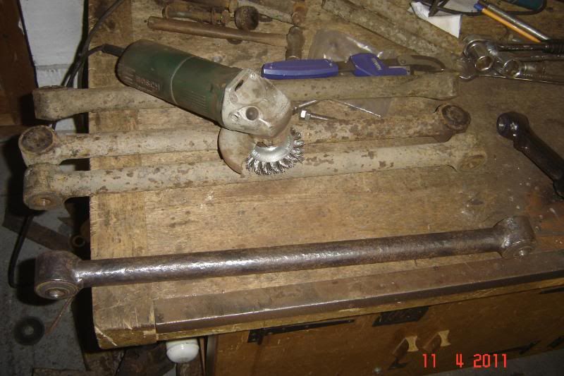
I love messing around with the lathe
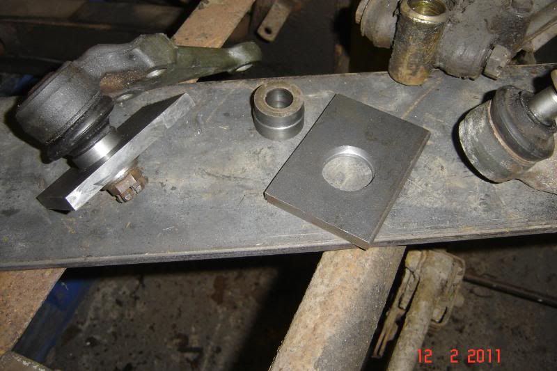
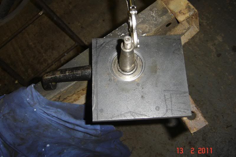
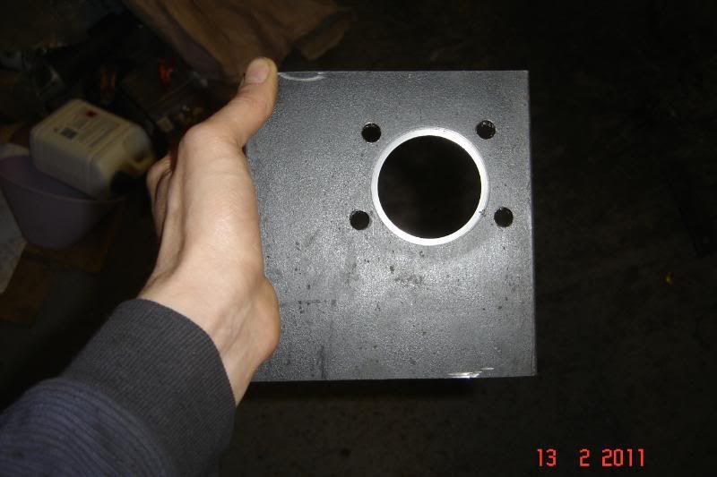
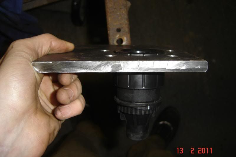
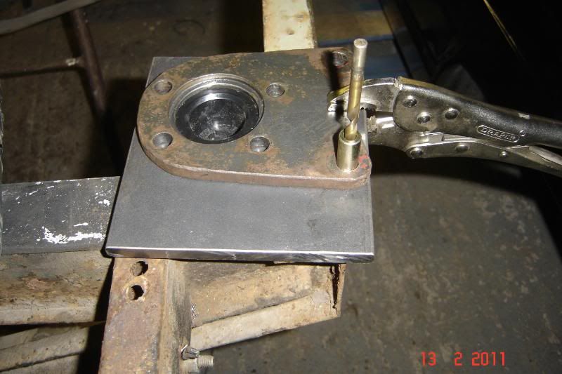
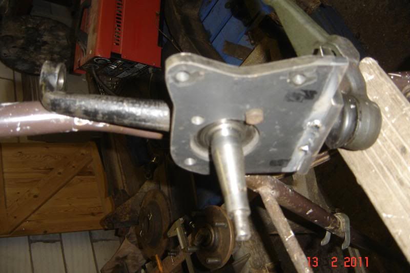
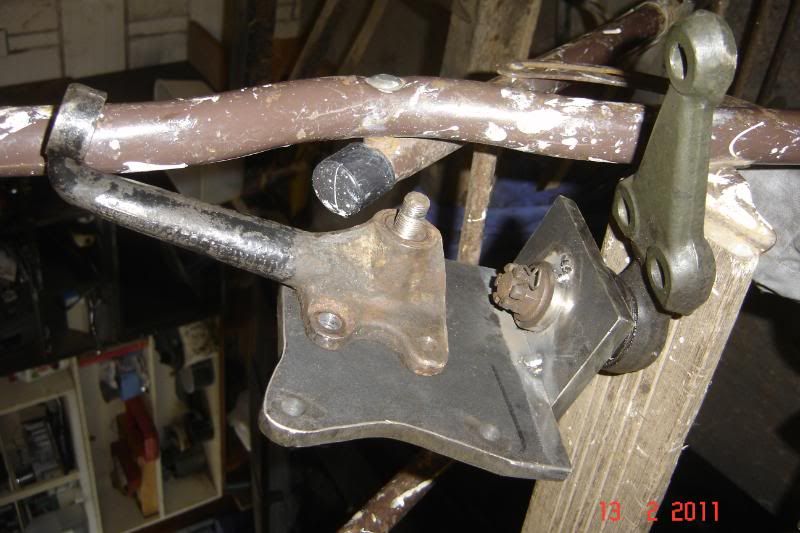
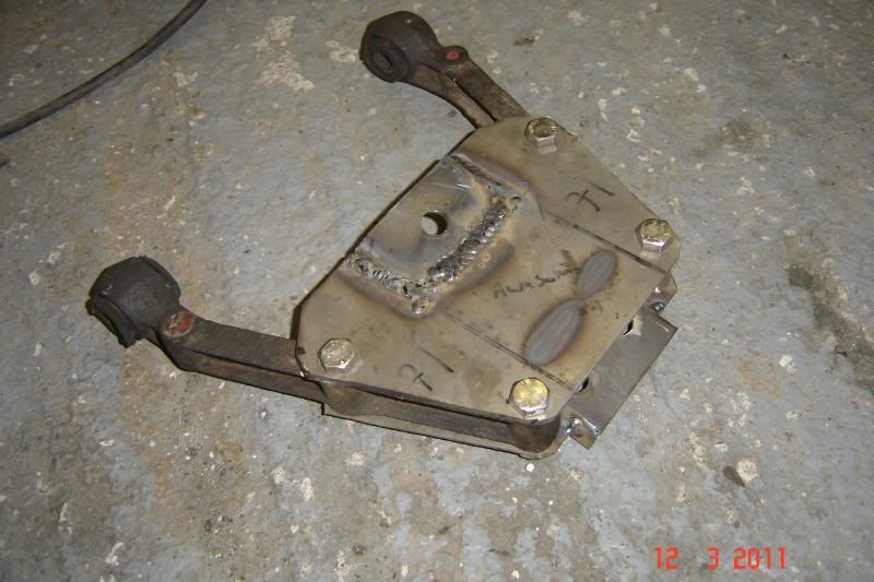
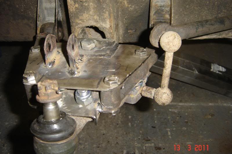
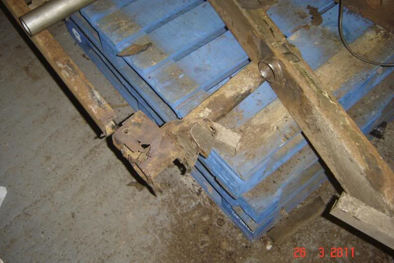
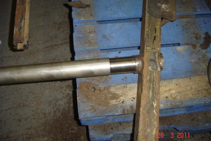
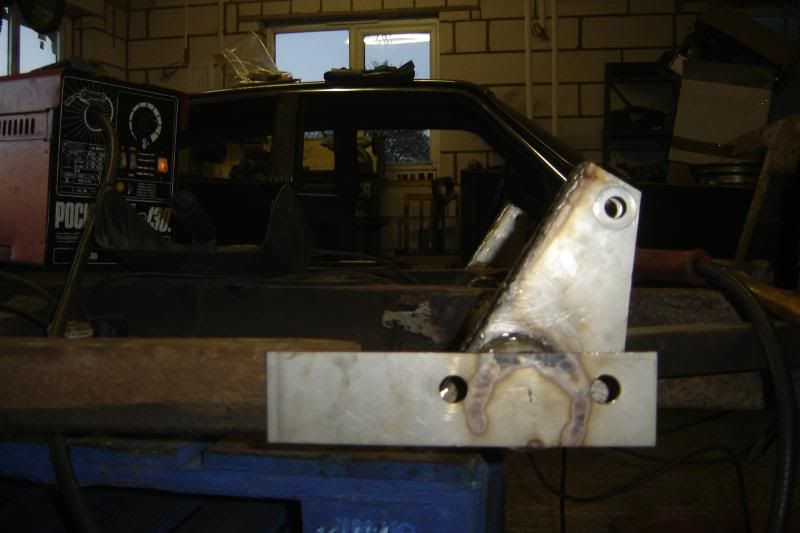
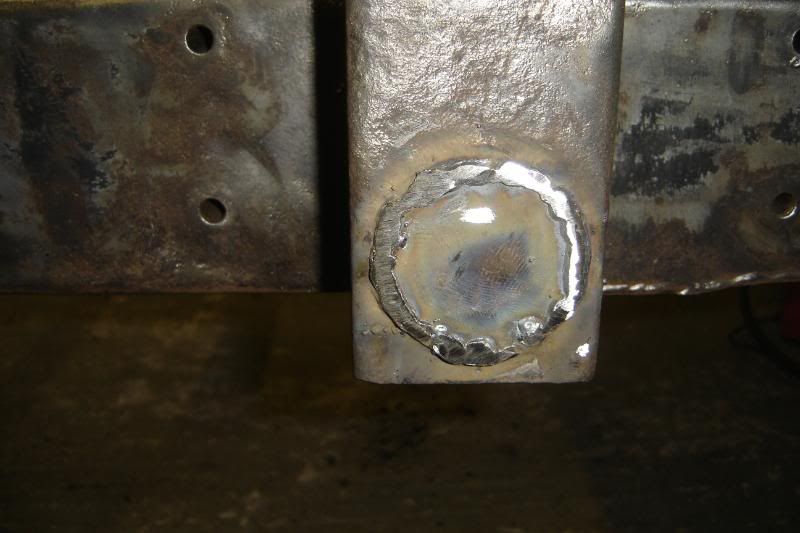
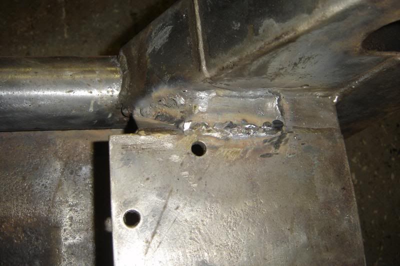
There's a step in the part to ensure the suspension can't collapse if the welds (yet to come) should fail
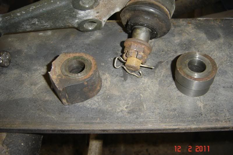
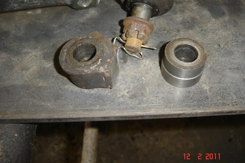
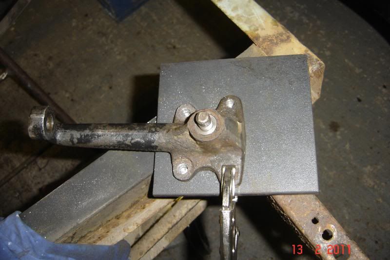
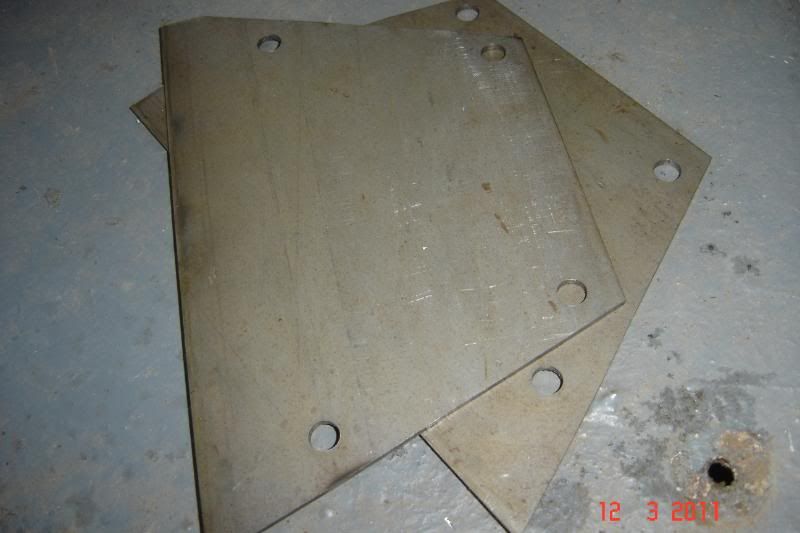
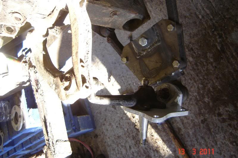
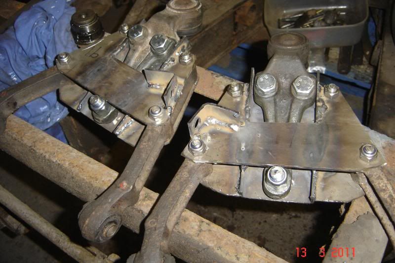
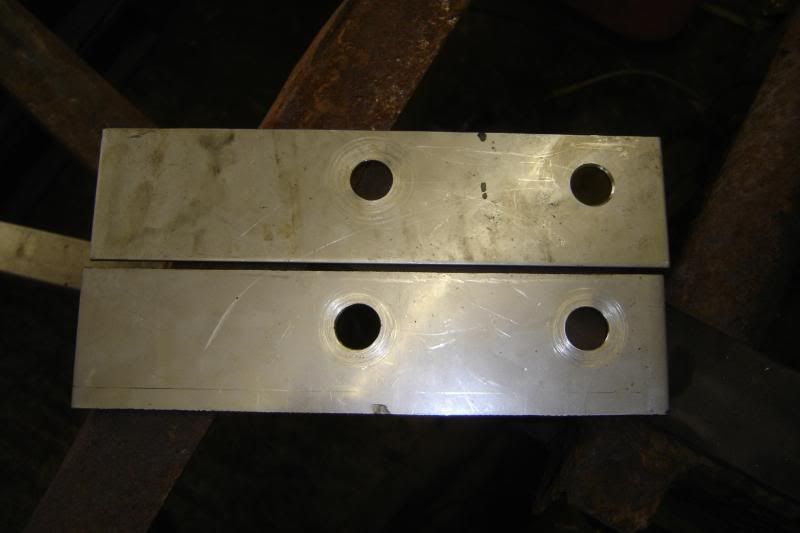
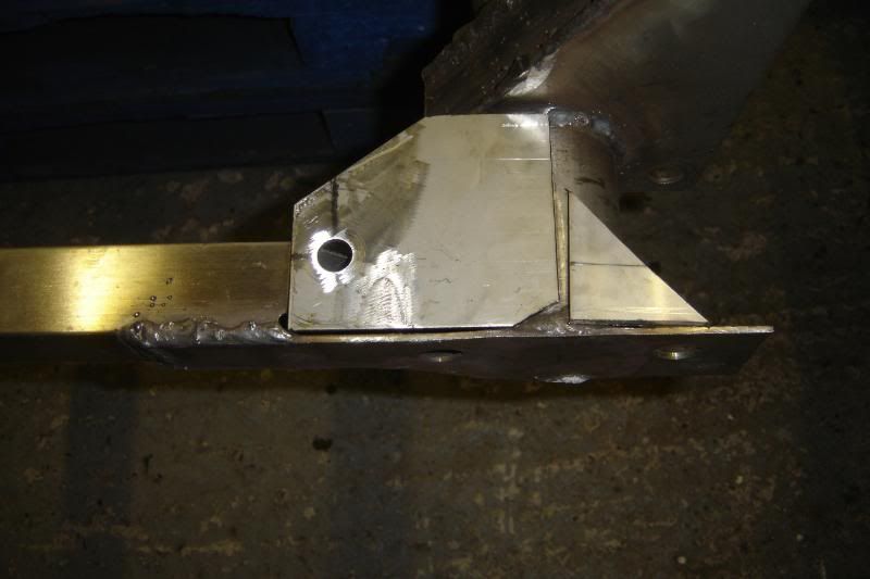
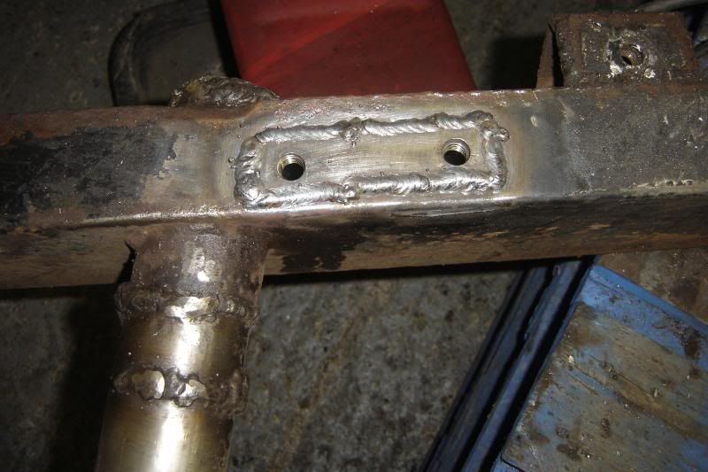
Turned a 10mm steel plate to suit the ball joint mount, these will be welded together
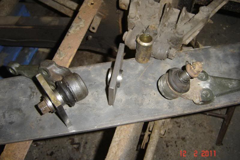
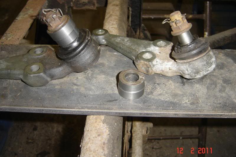
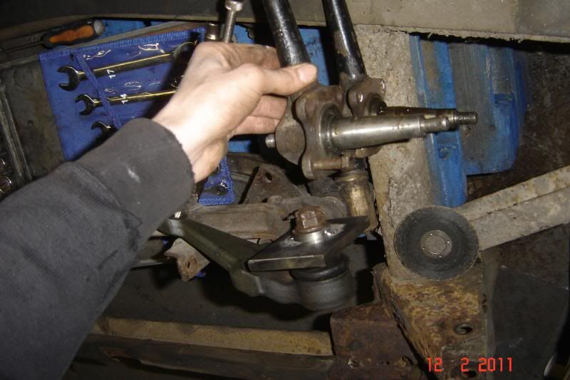
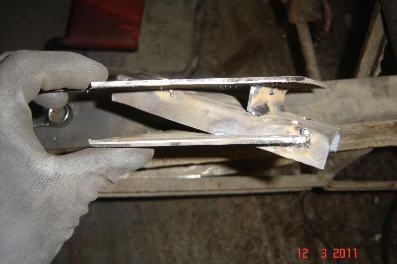
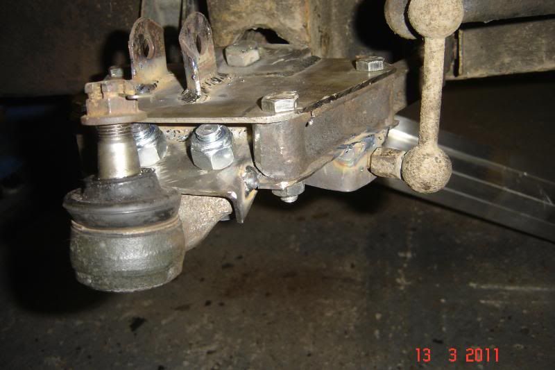
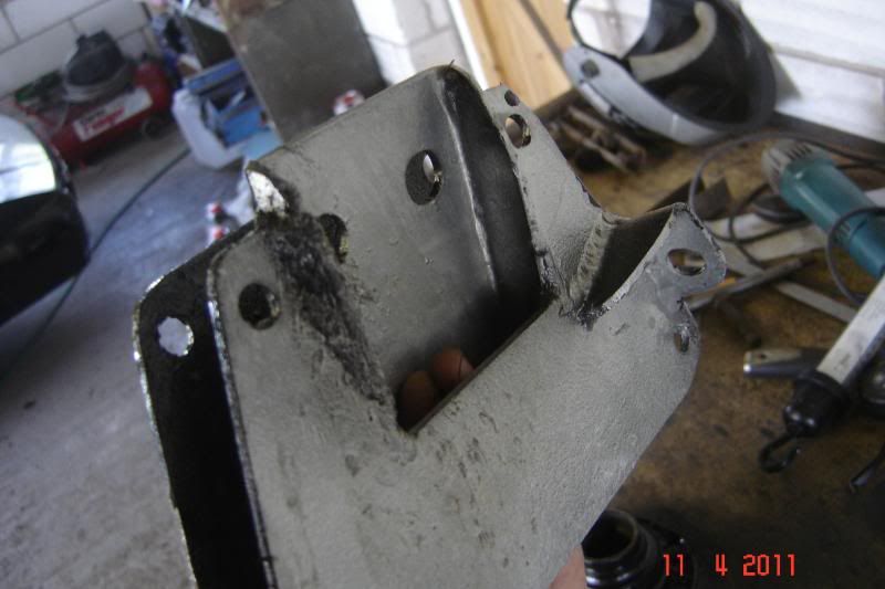
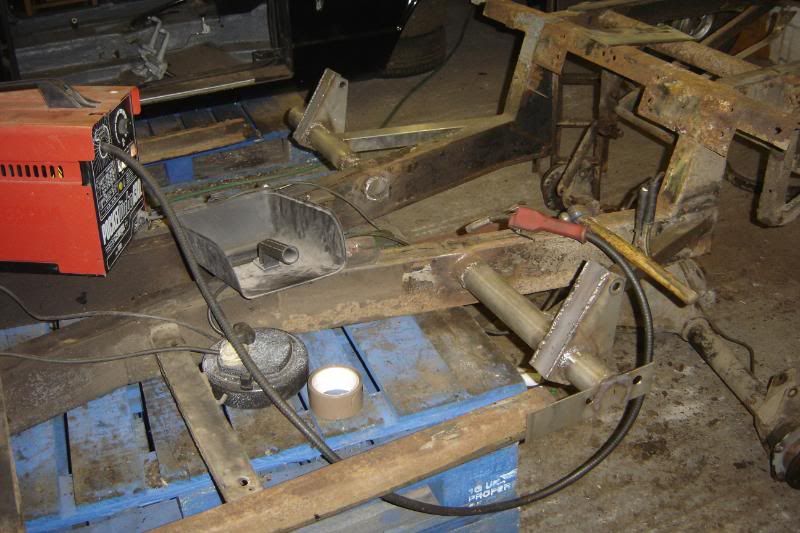
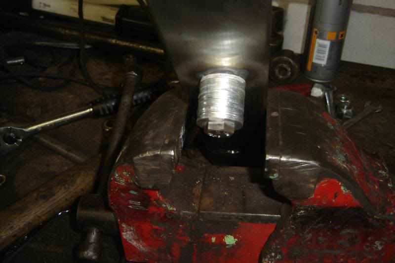
Cut the bottom off the upright, it took forever, they are VERY strong, no wonder they're so much to buy
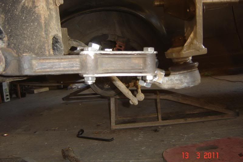
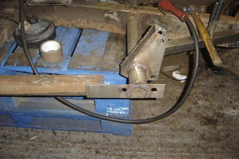
Then went about making up the new caliper mounts that will drop lower than the last ones to meet the ball joint mount
More to come, I'm hoping to get it all welded up tomorrow. The lower wishbone and shock mount are next, but that might have to wait a bit.
______________________________________________________________________
Got it finshed today, got all the holes drilled and upright bits cut to shape. I used a "drill doctor" drill bit sharpener and I cant sing its praises enough. I sharpened one 10mm bit and put a "split point" on the end face. It then drill 16 holes through 10mm plate without so much as a pilot hole and its still cutting fine.
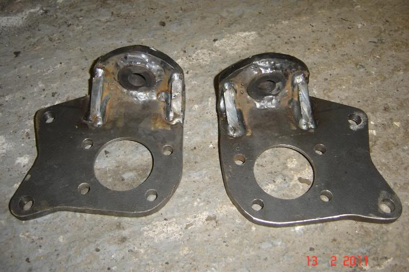
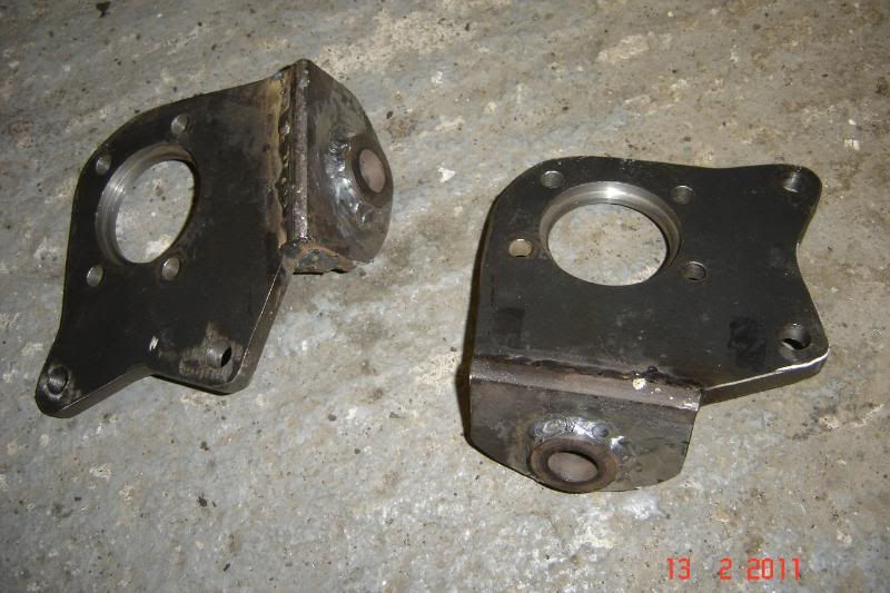
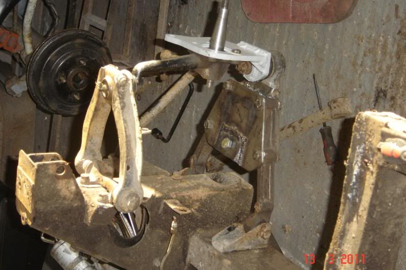
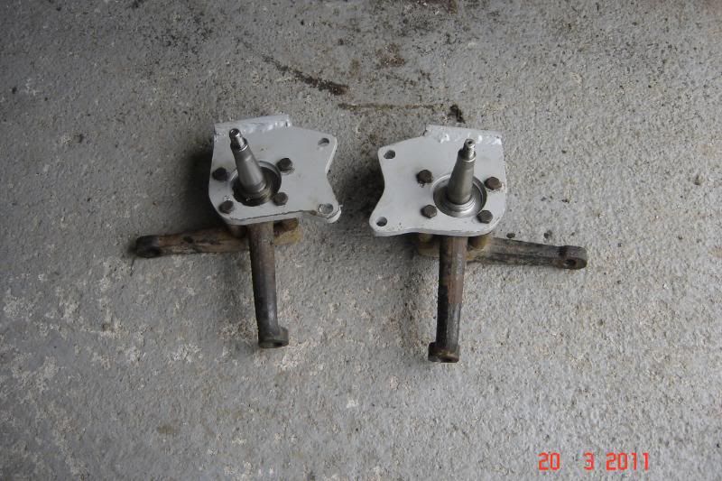
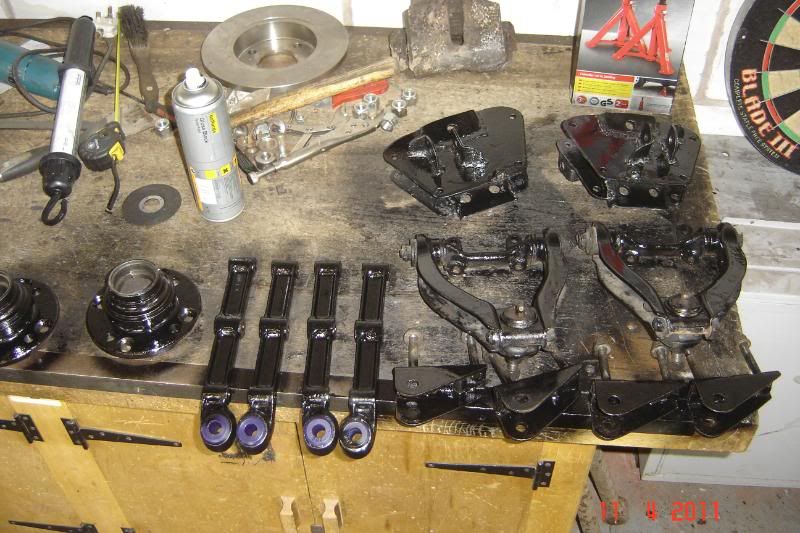
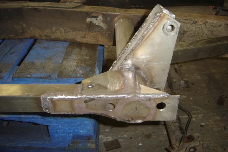
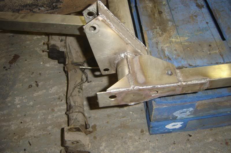
Anyway here are some pics of the finished uprights.
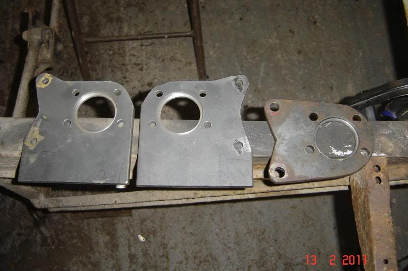
It took a while to get the end of the caliper mount to the right angle for the correct king pin angle.
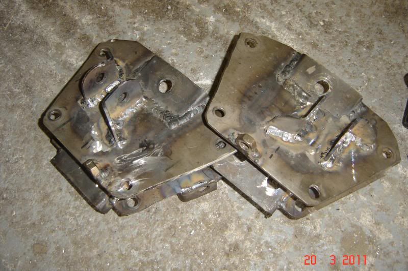
Took them to a friends house as he has a beast of a welder and got them all welded up added so webs. I was a bit worried the bits from the supra uprights might not have welded but it welded beautifully. As a test I welded something to the supra upright and beat the s*** out of it with a hammer, I welds just fine!
Can't wait to make the wishbone mounts next.
the brackets I had made a little while ago are up for grabs now. I'll do another post for them soon.
_____________________________________________________________________________
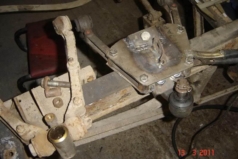
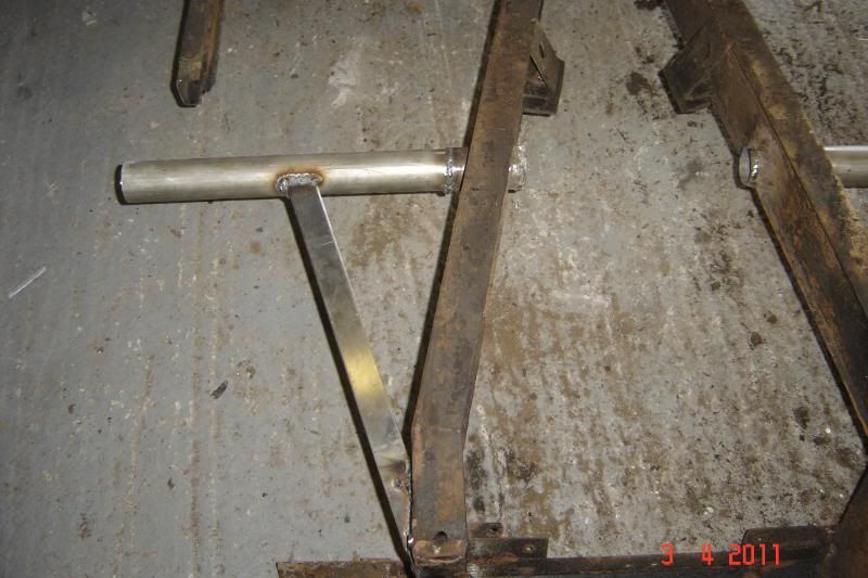
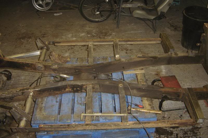
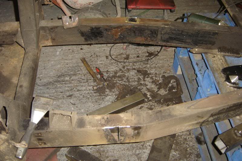
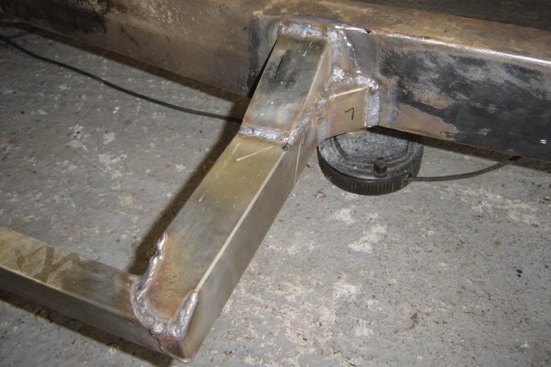
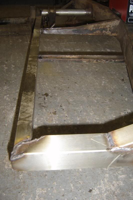
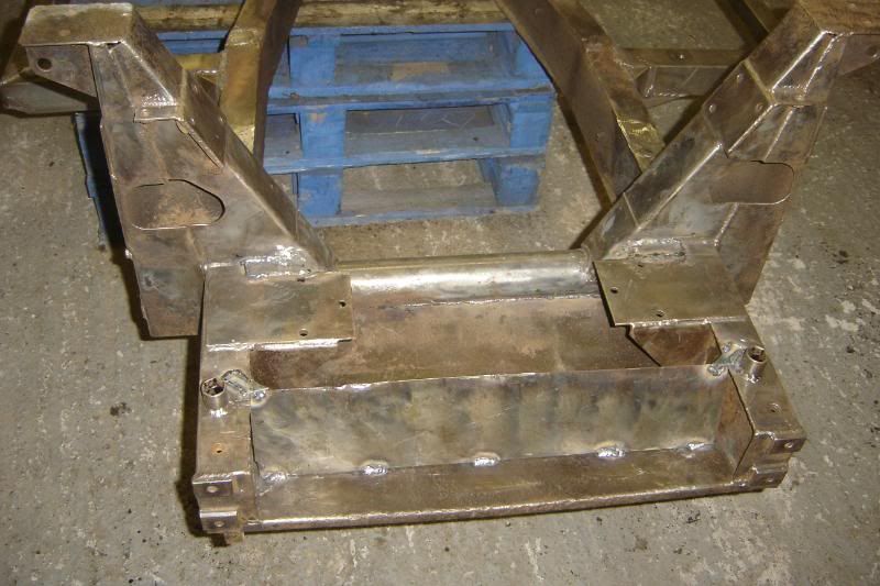
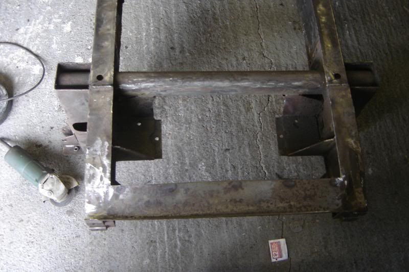
The lower wishbones are getting there now, took me a while just looking at it Still got to weld on the shock mounts, steering stops and anti roll bar mounts. Hopefully tomorrow if I can get all my work finished first
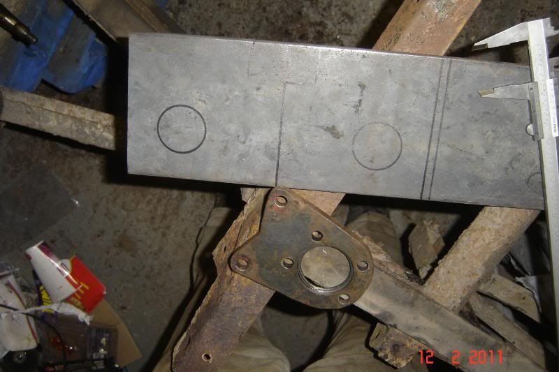
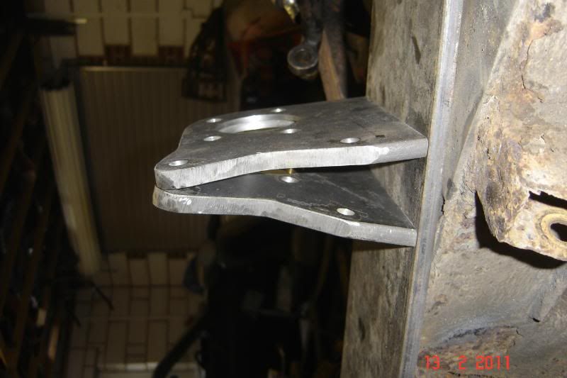
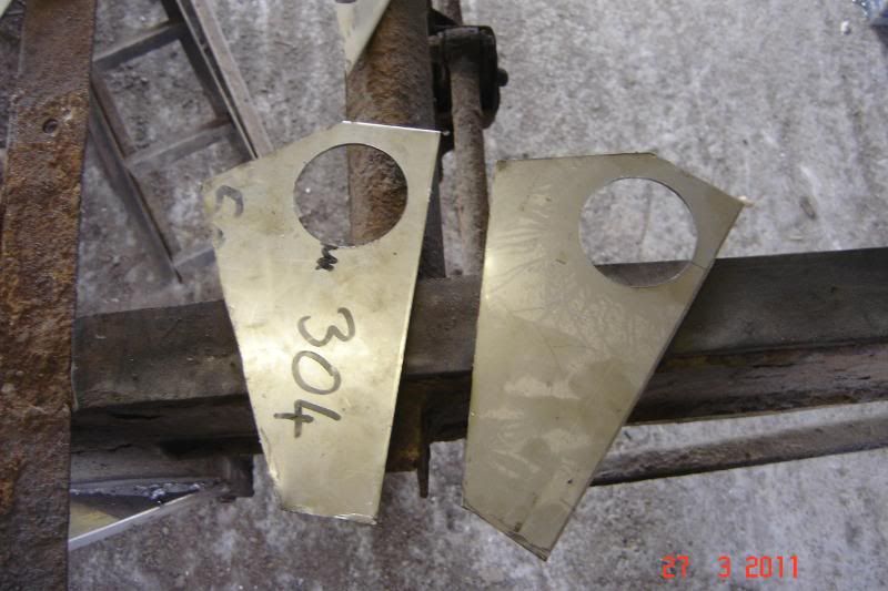
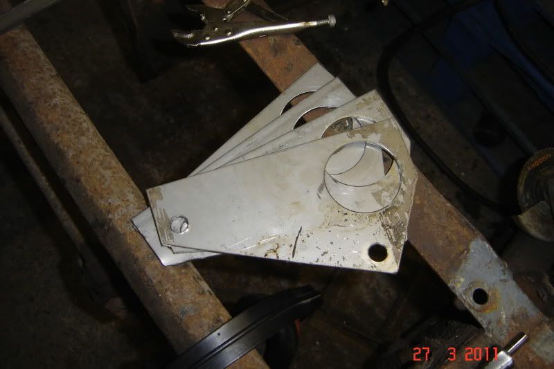
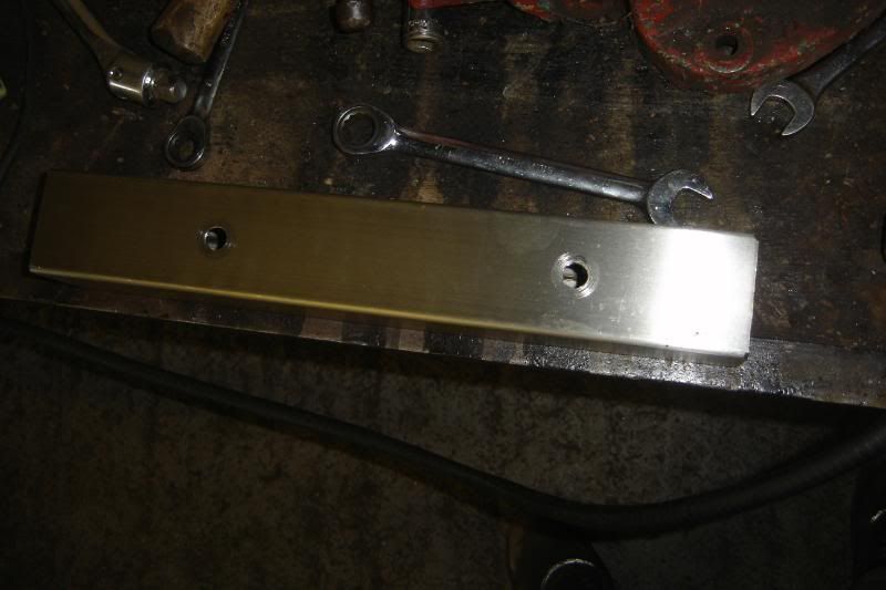
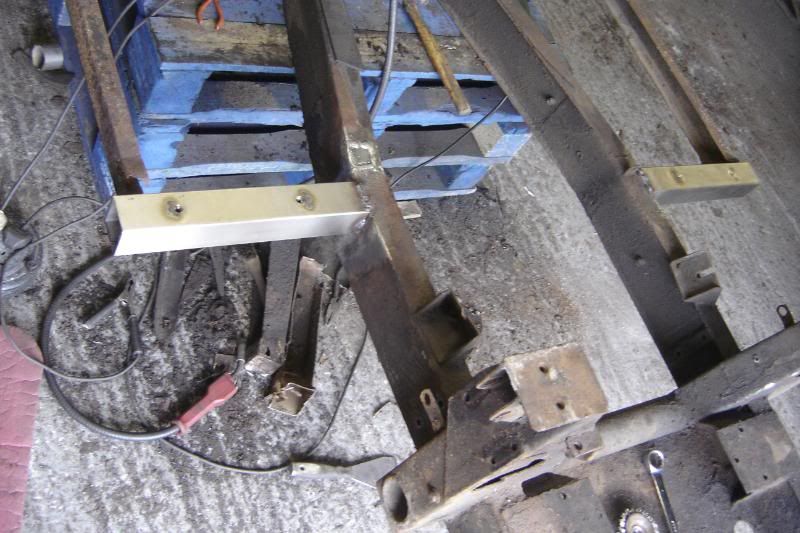
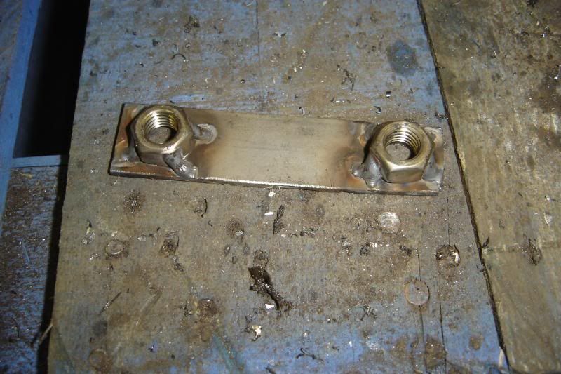
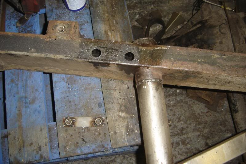
Cut and drilled 4 of these plates, the whole time they were clamped togther with mull grips (spelling?)
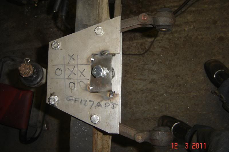
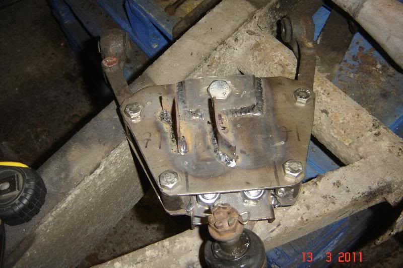
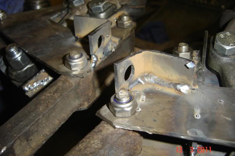
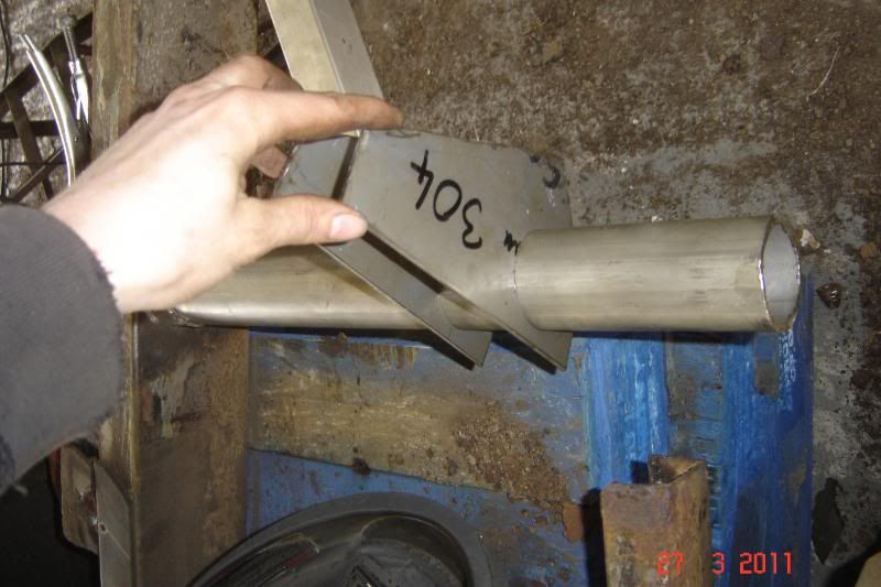
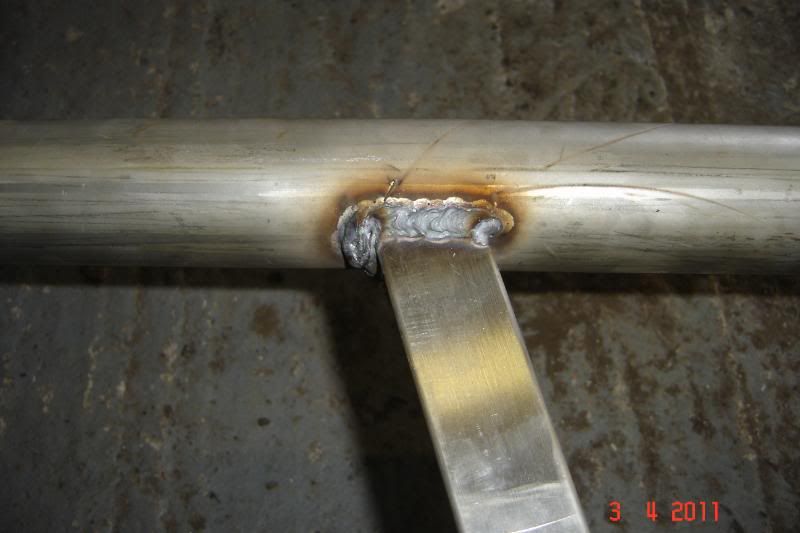
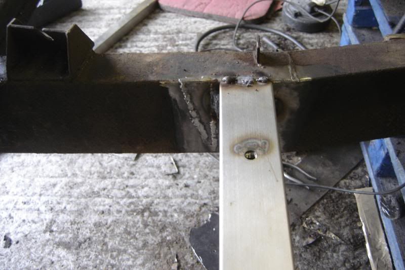
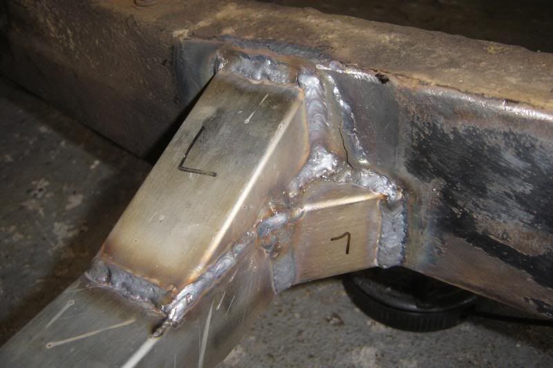
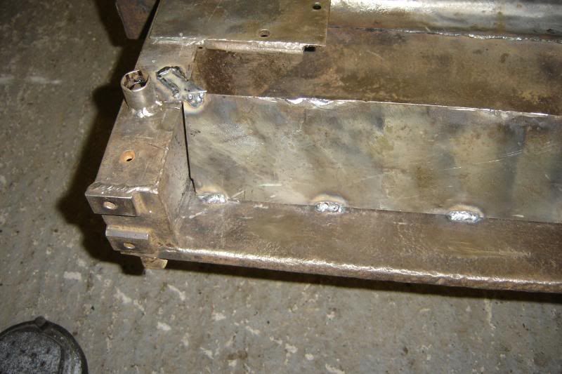
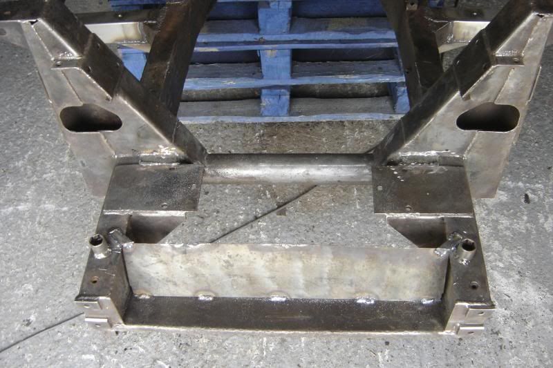
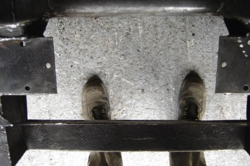
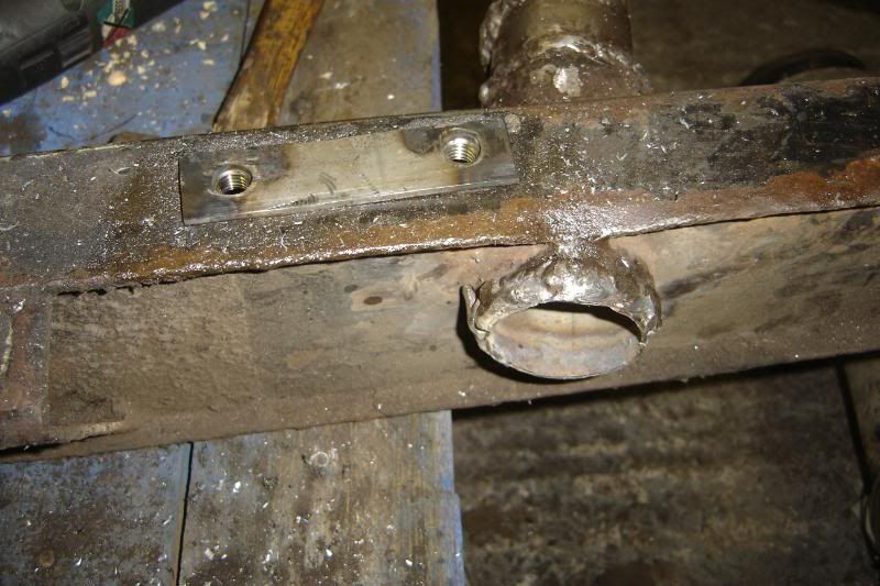
After much thought I marked them up and cut them to slot through the ball joint mating face:
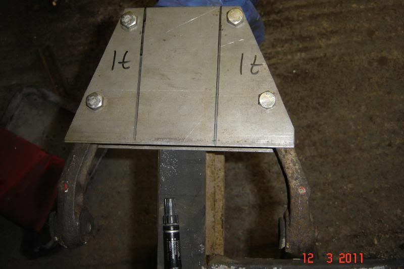
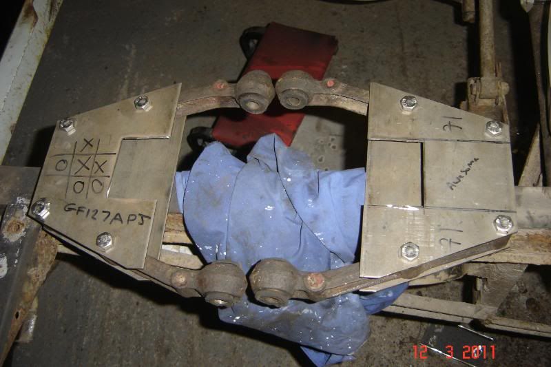
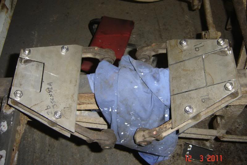
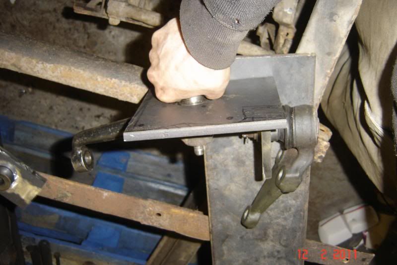
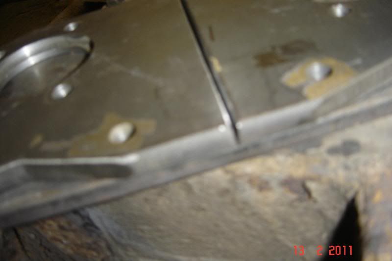
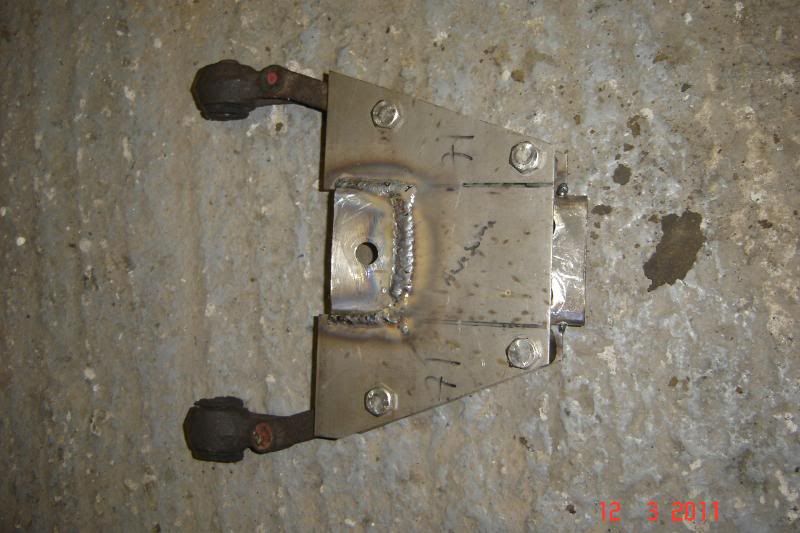
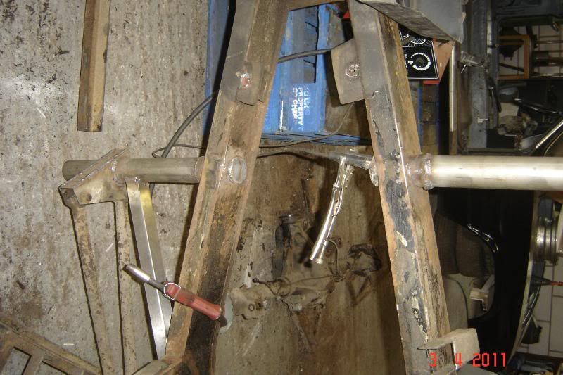
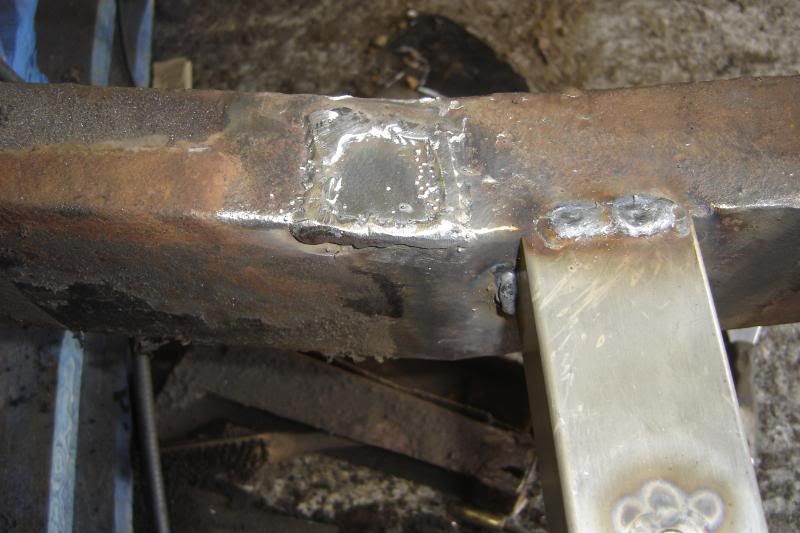
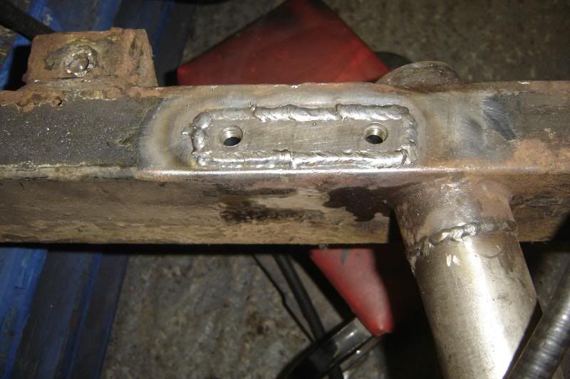
Then tacked and welded them up, as I said there's still much to do, its been a real weld-a-thon today and I've just about had enough for a while:
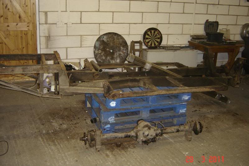
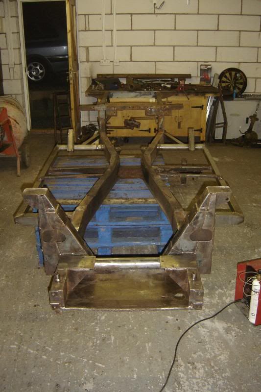
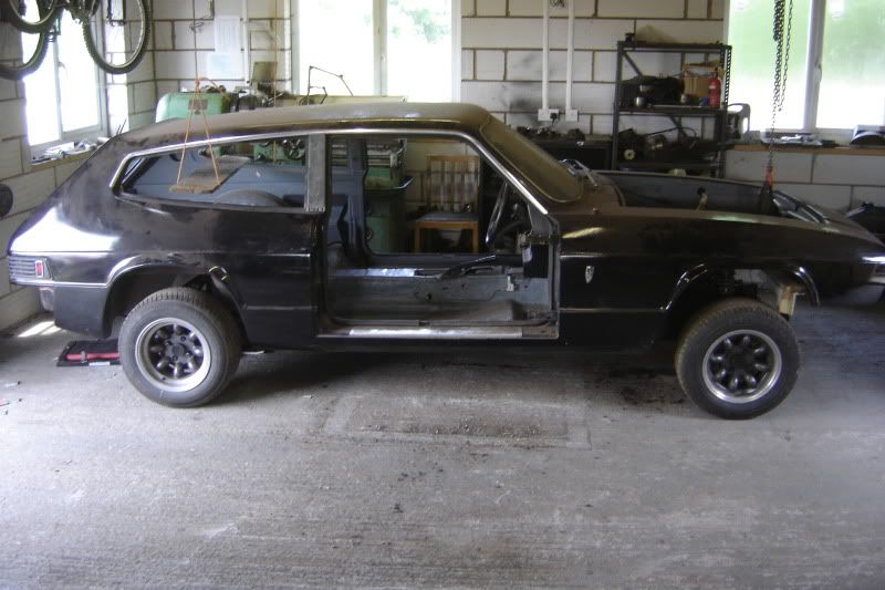
The poor car hasn't been this apart in my ownership.
_________________________________________________________________________________
Made some more progress today, they're nearly done now, these represent so much of my time, its getting rediculus, and I haven't even started on the major chassis work yet........ but its so much fun!
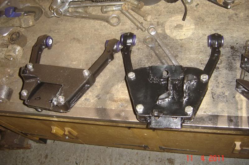
And here are some recylced wishbone mounts for hte shocks to mount
And some anti-roll bar mounts
It was convinient that the anti roll bar tie links reversed so I could weld the brackets on more neatly than the original parts to save a tiny bit of weight on these already pretty heavy wishbones
More to come, maybe next weekend, I might get the front section of the chassis cleaned up and painted too.
_____________________________________________________________________________________
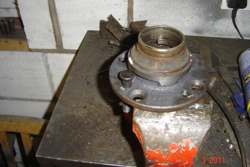
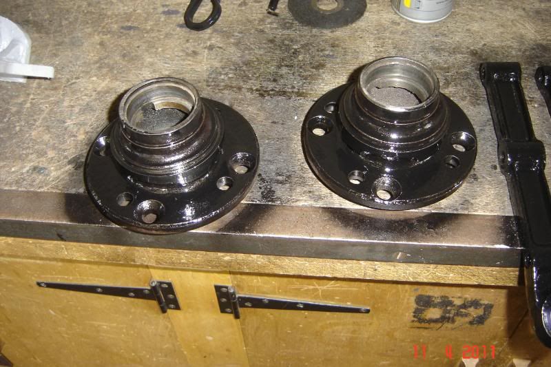
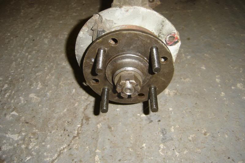
Another thing ongoing is getting the hubs redrilled for the Caterham wheels:
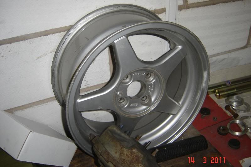
First thing was to get the hubs off, hmmm:
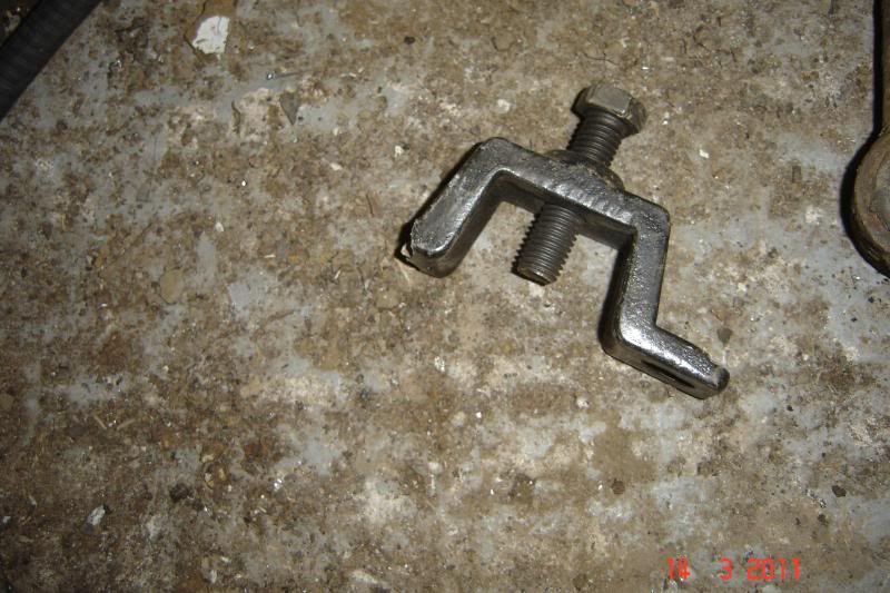
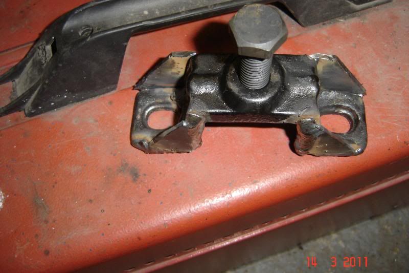
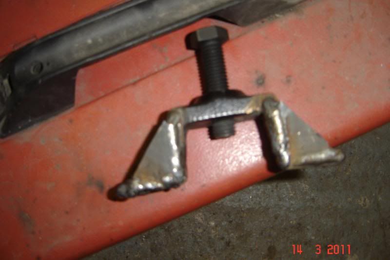
I added a bit more strength and eventually they came off:
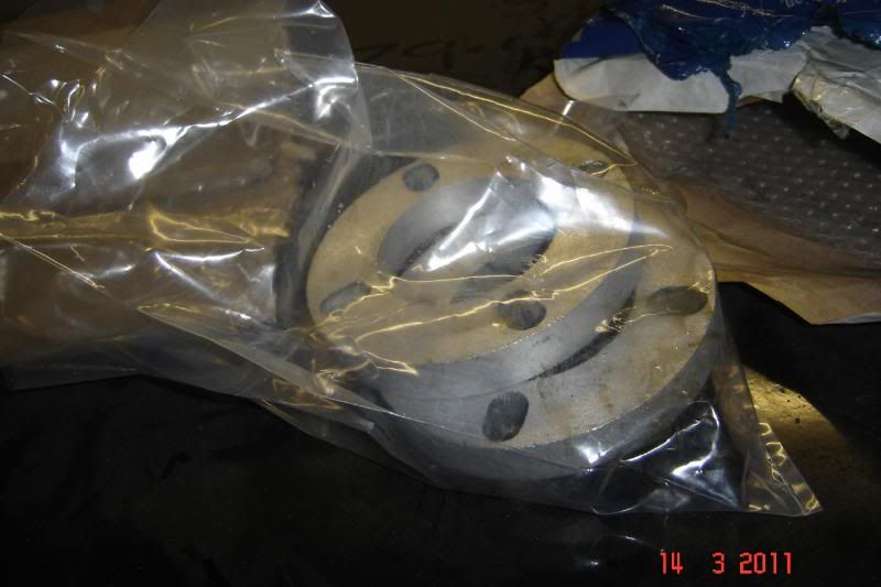
Got the spacers and extended studs from Rally Designs:
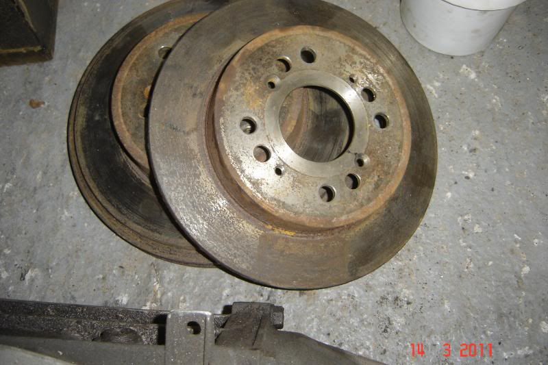
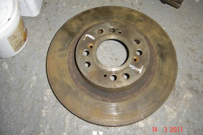
Discs redrilled on a roatary table in a local machine shop:
And finally the hubs:
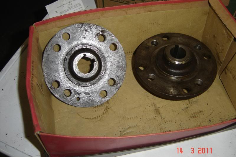
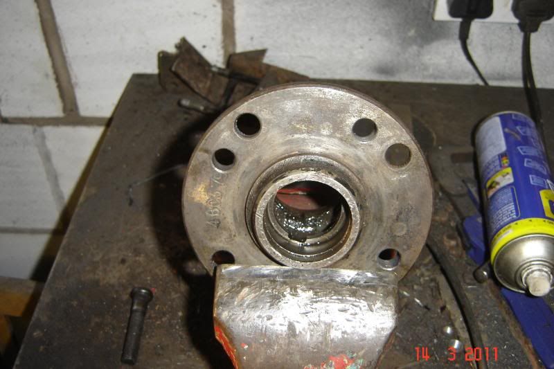
Had to turn off the old brake disc brackets in order to get the studs in:
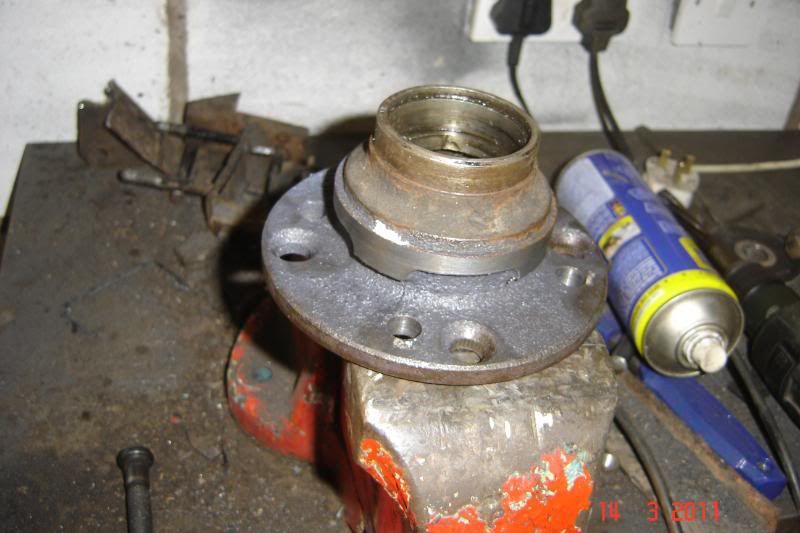
Next the surface on the back side of the rear hubs needs flattening so that the studs can seat flat.
More to come
__________________________________________________________________________________
A little update.
These wishbones are taking ages! but they're finally ready for some paint. All that suspension stuff just takes so long to clean up, I'm slowly getting though it, the wishbones are drying as I type:
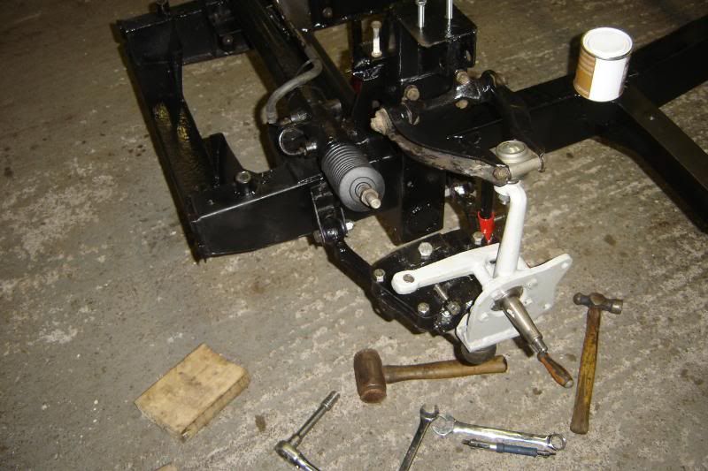
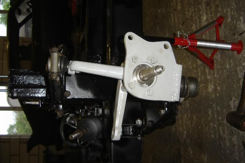
I've taken the plunge and cut up my two best upright to make the new ones, this is next for paint:
The New lower bits now have have adjustable lock stops and I thought I've cut the first attempt at shock mounts off (as they were a bit thin in places) and make up some new ons out of thicker newer steel. They're still not hte 4mm of the originals but they're not nearly as tall so at 3.2 ish mm they should be fine.
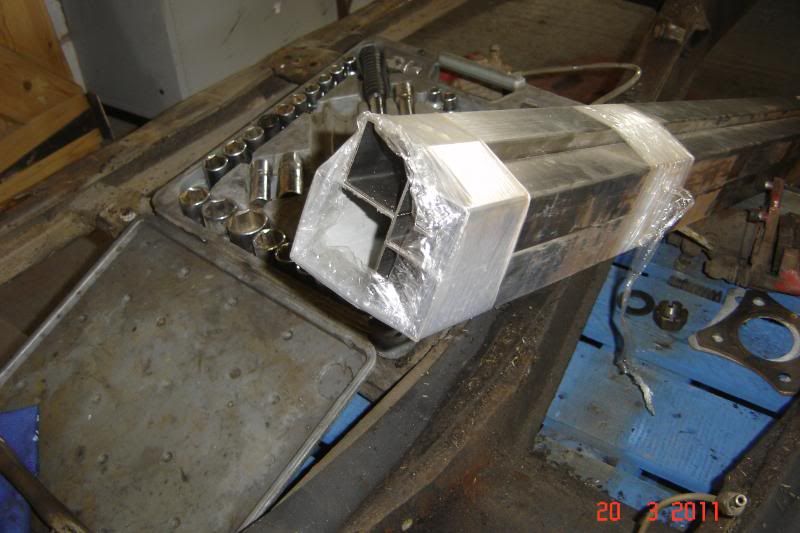
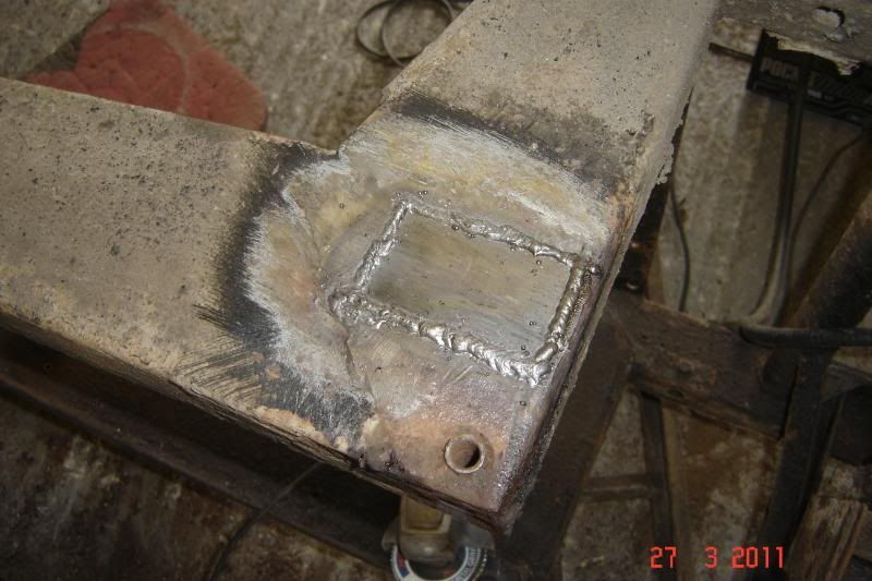
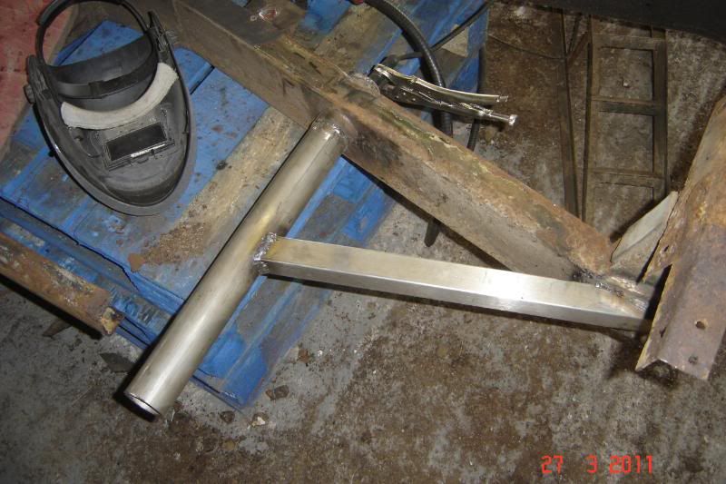
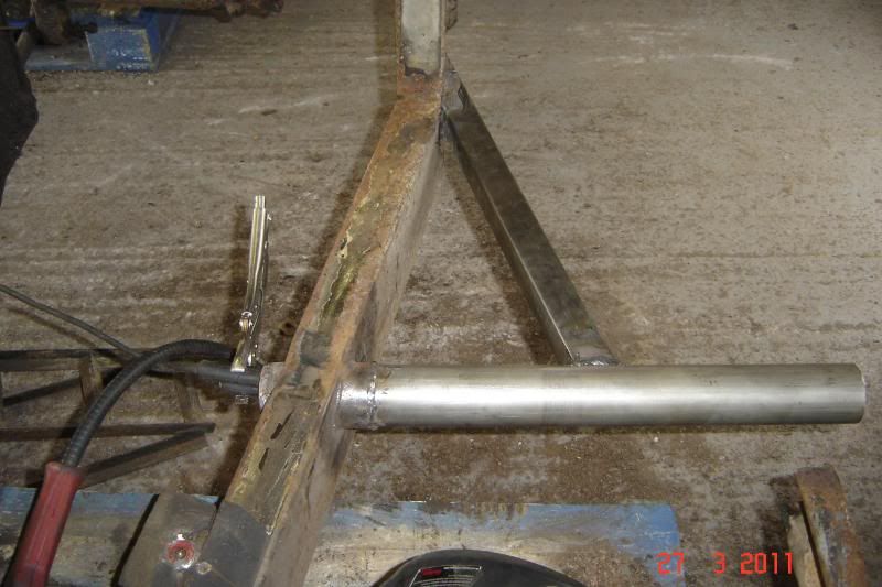
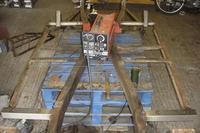
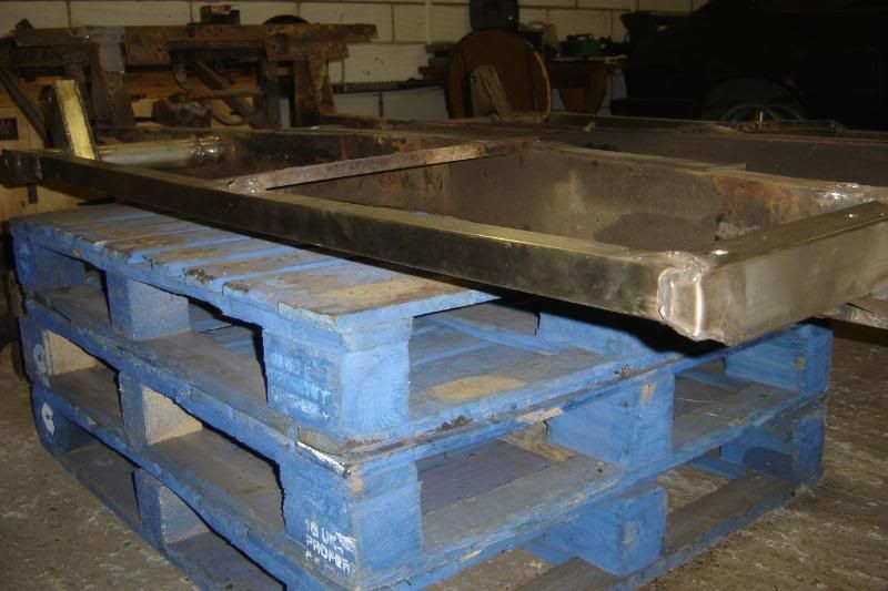
Here's the 316 stainless thats just waiting to become a scimitar outrigger, the tube is to replace the part of the chassis that the axle mounts to, it too is stainless 304 this time:
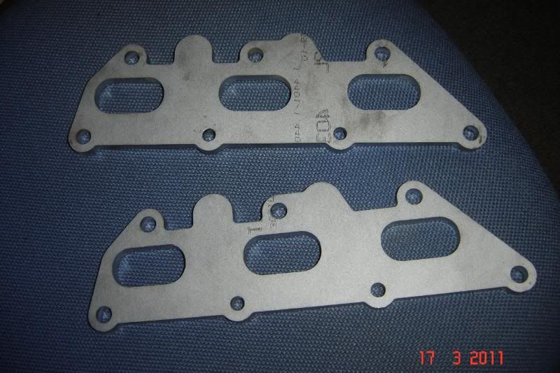
Sticking with a theme, these are the stainless exhaust manifold plates that arrived recently, laser cut! can you guess the engine they're for?
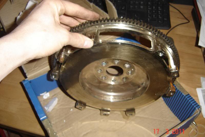
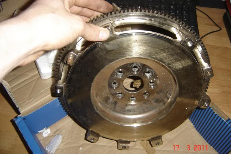
And for the same engine (going into the Scim) the is a lightweight flywheel, that weights over 10kg !!!! less than the original, it was machined from a billet, its little engineering artwork:
More to come tonight maybe.
Please feel free to comment, I'm not sure how many are actually interested?!
______________________________________________________________________________
Another quick update,
All the front suspension bits are either painted or ready for paint (as I ran out).
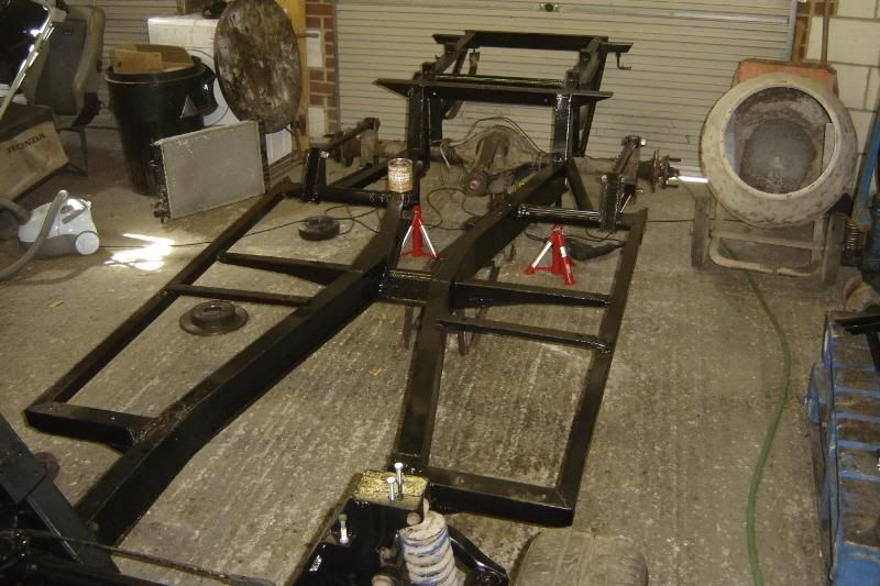
The bits are up in the rafters I've made a token start on the chassis.
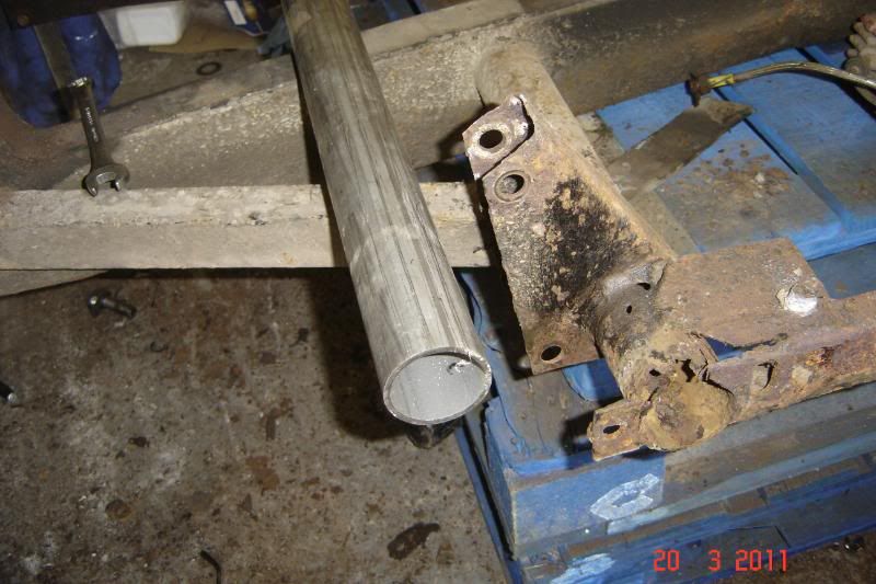
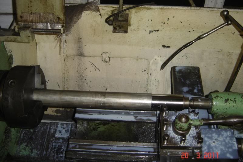
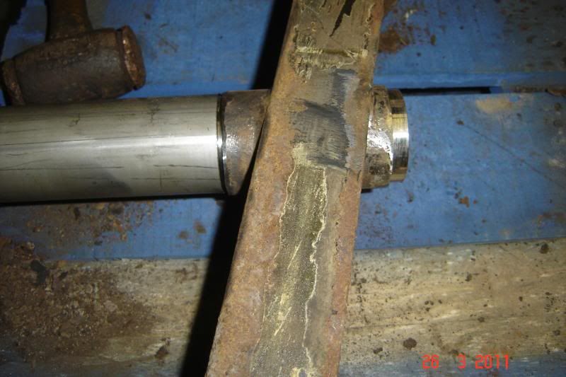
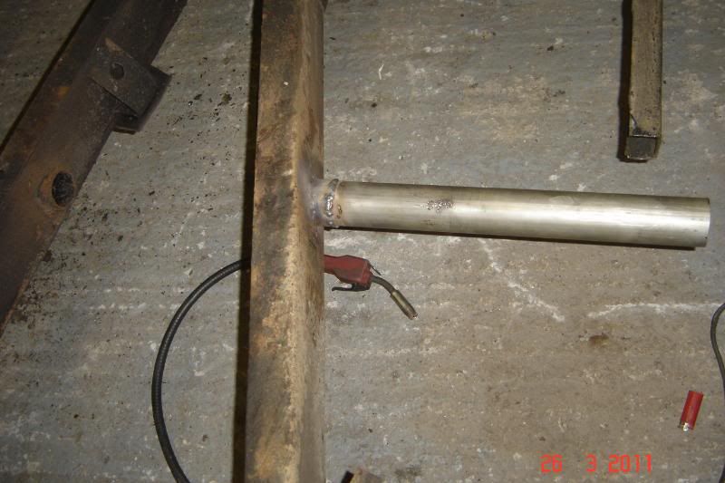
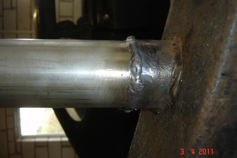
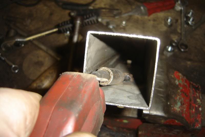
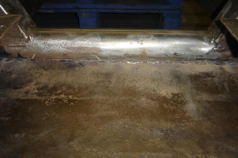
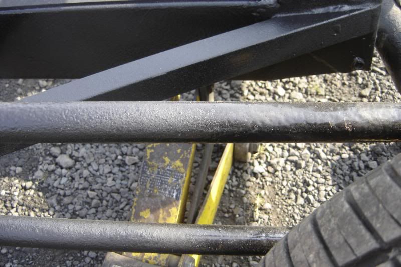
This tube is to replace the rusty one benieth it. Its slightly thicker walled and slightly less diameter. I'll cut the old rusty one off leaving a 10ish cm section where its welded to the chassis main rails, then turn down the new tube and slide it into what is left of the old then weld it all up. Here's the new stainless tube being turned down.
_________________________________________________________________________________
Thanks Burtle you'll probably get lots of bugging questions when I finally get round to pulling the engine out.
Max, the Omega flywheel is indeed a dual mass beasty a right beasty and 15kg too. That sounds like an amazing project, I've often thought if I could have any job in the world, anything, it would be to set up a buisness turning the classic car of the customers choice in a hybrid machine, that would be just awesome. Anyway I degress, this flywheel is about 28cm across and about 6cm deap, but you could probably add another 6cm to that with the clutch mounted. if you're going to the trouble of putting a generator in there then you'd be best off ditching the gearbox anyway leaving lots of room. Generator and Motor would have losses, Gearboxes and axles also have losses, so best one or the other rather than using both, enless I've missunderstood what you're thinking of???
Thanks a lot for all your comments folks, keep them coming! any more thoughts on retrofitting those poly bushes??
___________________________________________________________________________________
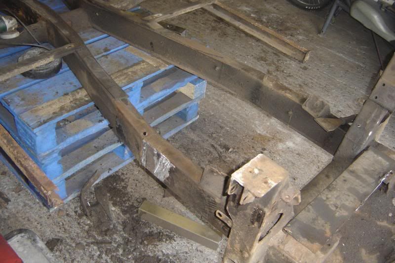
Had a couple of hours on the car this evening, hopefully, I'll get nearly a full day tomorrow. The chassis project has finally begun, this one's looking to a long haul!
Cut the old tube off:
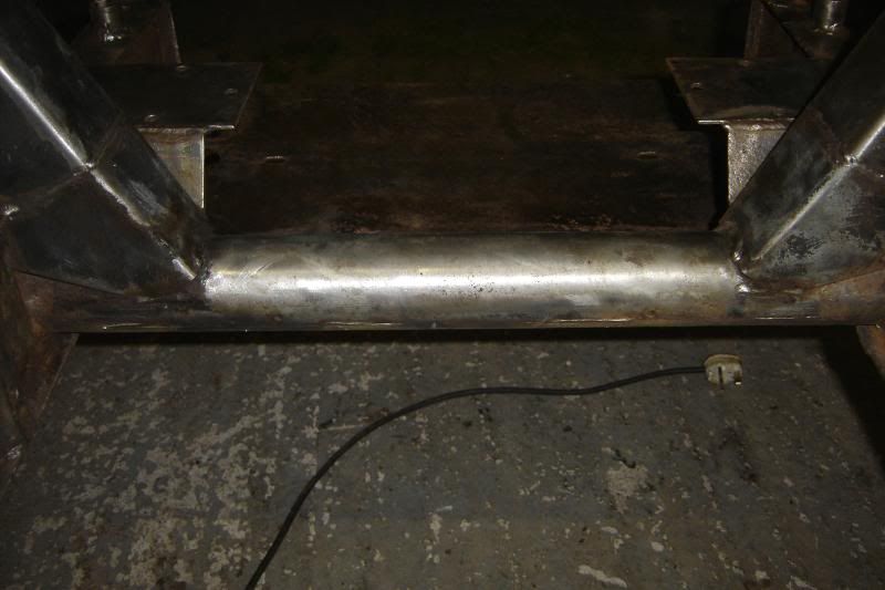
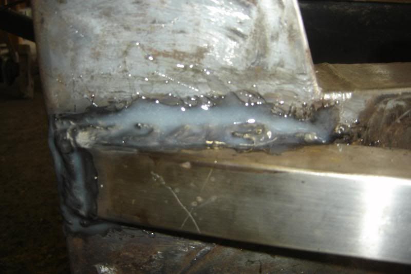
And turned the stainless tube down so that it would slide it, this makes it about 2mm wall where its sliding into the chassis, and just over 4mm wall everywhere else.
It was a tight fit so had to hammered in:
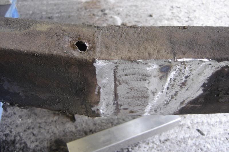
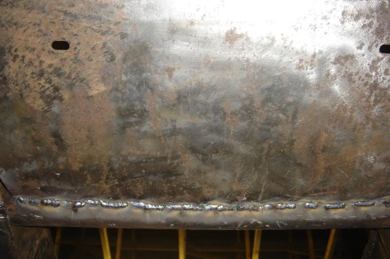
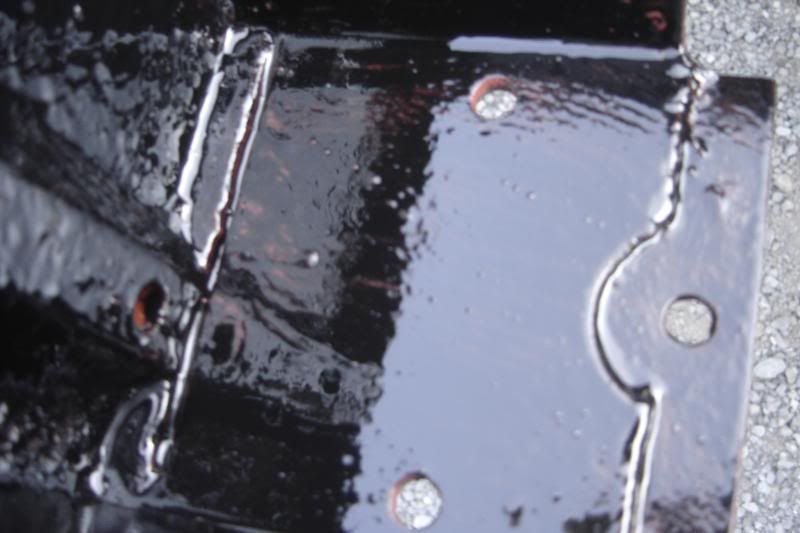
Bird poo... sorry I mean, welded it in place with 304 welding wire:
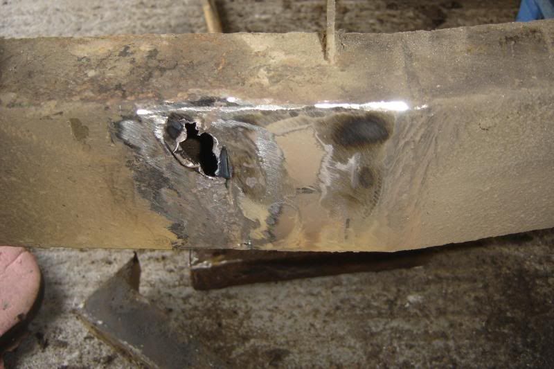
After cutting the supporting U section off it became that the chassis had a hole, so that'll be tomorrows work, along with putting the new stainless support in.
More tomorrow!
____________________________________________________________________________________
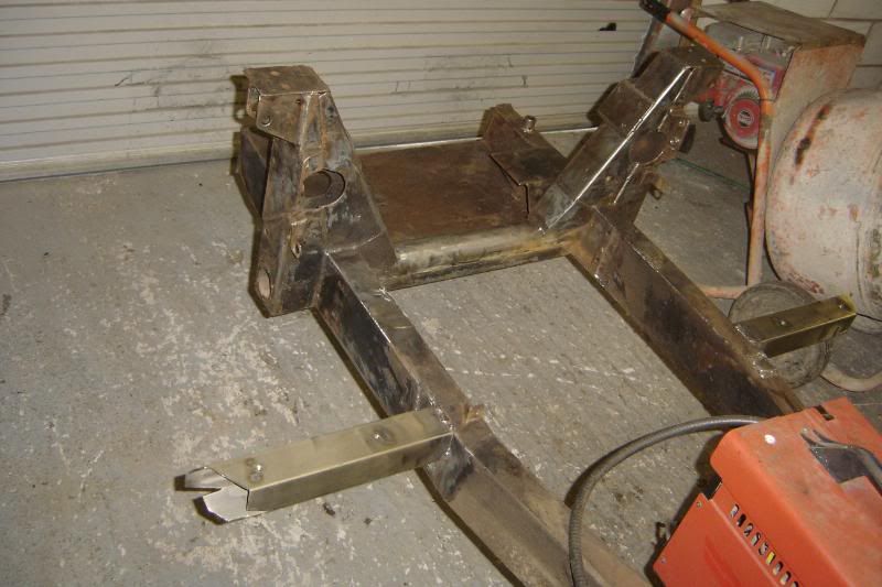
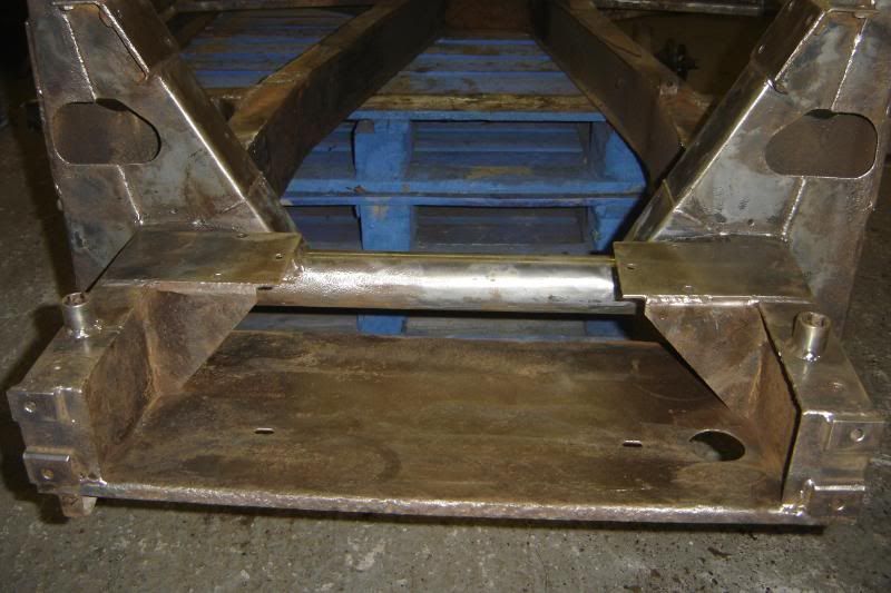
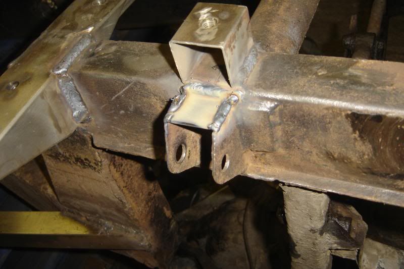
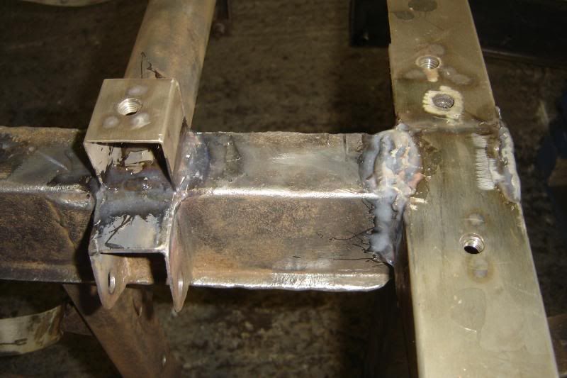
A mid afternoon update, The hole is patched and the box section support welded on (stainless 316 box )
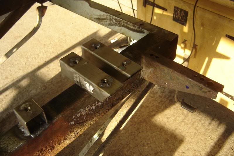
And two of the four stainless brackets are nearly made up,
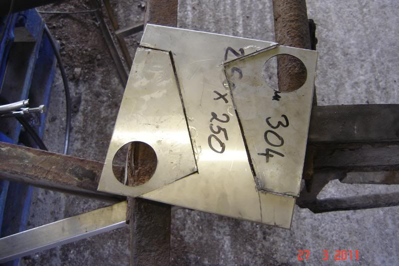
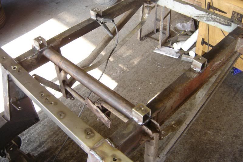
I'll make all 4 then clamp them together to make sure the holes are in indentical places. Then mount the axle with the original rustly bits on the right to properly locate the brackets on the left, then weld them up. Hopefully today
____________________________________________________________________________________
I haven't got on very well today been so ill just moving around the garage slowly like a zombie. I'm out of grinding discs, blunted some drill bits and knackard the stepper drill bit, and the boring tool for the lathe
The brackets are nearly done but the holes need to be a bit bigger (hense the stepper drill bit broke)
Hope to get more done next weekend, hopefully I'll bring home less work from work if you know what I mean
_______________________________________________________________________________________
Some modest progress this weekend so far.
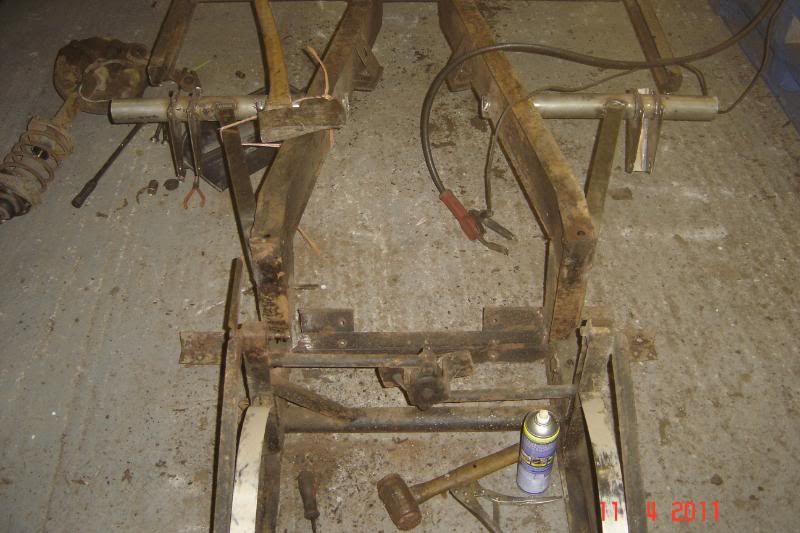
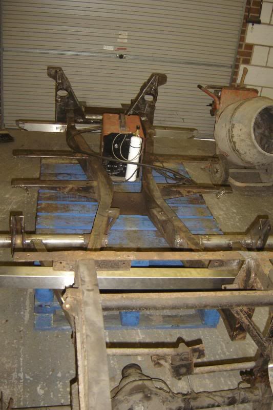
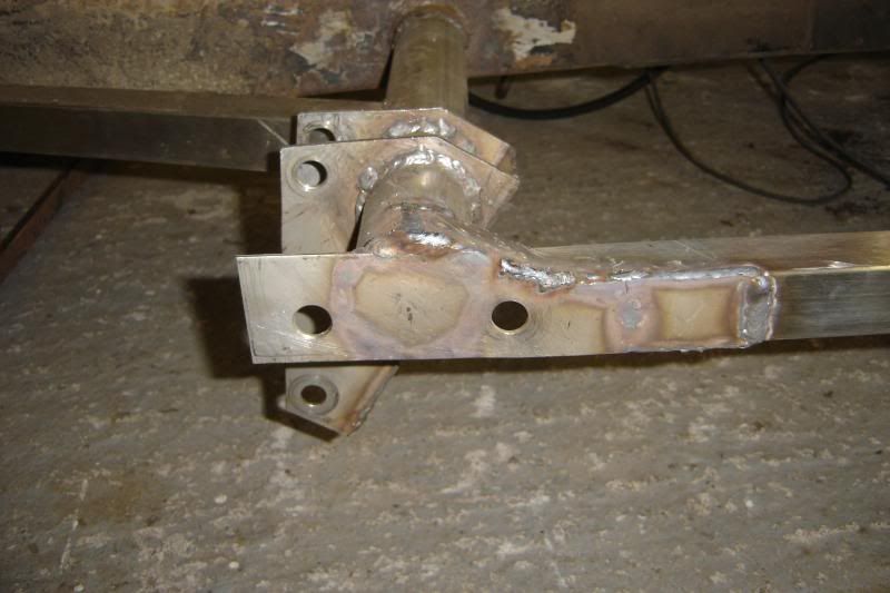
Got another step drill bit from the bay and after another session with very littl progress in the pistol drill, I mounted the drill bit in the chuck of the lathe and set the speed really low, and it tore through the stainless in seconds, so all the holes are done! Mounted the axle, so that the original rustly mounts on the left side hold the new ones in the right place on the right side and welded it all up. Now probs so far. I've set about doing the same thing on the right side of the car and got pretty far with it only to find that the tube hasn't aligned itself like the left side did and the tube is almost an inch further back at the end so I've got to cut it up again and weld it up in the right place I was so careful too
Oh well, I'll be well practiced for the next try. Here are a few more pics:
One more week of work left, then a solid 2 weeks off to get it all finished and back on its new wheels, watch this place.
___________________________________________________________________________________
AND FINALLY TODAYS WORK
Right, I'm on holiday, and work comenced today, and will continue every day
Today, I put the mistake right and set about welding the brackets on and then ran out of Argon so I started on some of the suspesion bits.
Heres the chassis upsidedown amit welding:
Painting the front hubs
The front wishbones back from being galvanised
Then painted to match everything else, its a case of trying to make it look as inconspicuous as possible to avoid the SVA criteria with the MOT man (its very wishy washy)
I dont know if anyone else gets this, but when I've been working with the grinder and I blow my nose in the evening, its black and it kinda scares me. I've got a pretty good dust mask, but then the sparks can get under my goggles, and I've been to have a bit of metal cut out of my cornea before (I dont wish to repeat it). So to try to live a bit longer I bought this piece of overkill on the bay:

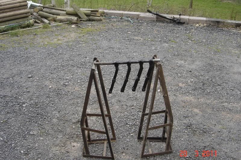
And finally this evening I've been cleaning the trailing arms ready for paint.
More to come.
So here's the progess on the recent projects lifted straight from the RSSOC forum.
I had an idea, and it goes a bit like this.
Had some old Supra bits lying around, they're strong! supra weighs 1600kg
Choppy Choppy
I love messing around with the lathe
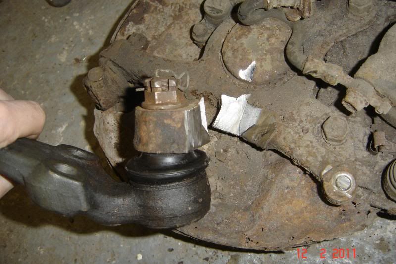
There's a step in the part to ensure the suspension can't collapse if the welds (yet to come) should fail
Turned a 10mm steel plate to suit the ball joint mount, these will be welded together
Cut the bottom off the upright, it took forever, they are VERY strong, no wonder they're so much to buy
Then went about making up the new caliper mounts that will drop lower than the last ones to meet the ball joint mount
More to come, I'm hoping to get it all welded up tomorrow. The lower wishbone and shock mount are next, but that might have to wait a bit.
______________________________________________________________________
Got it finshed today, got all the holes drilled and upright bits cut to shape. I used a "drill doctor" drill bit sharpener and I cant sing its praises enough. I sharpened one 10mm bit and put a "split point" on the end face. It then drill 16 holes through 10mm plate without so much as a pilot hole and its still cutting fine.
Anyway here are some pics of the finished uprights.
It took a while to get the end of the caliper mount to the right angle for the correct king pin angle.
Took them to a friends house as he has a beast of a welder and got them all welded up added so webs. I was a bit worried the bits from the supra uprights might not have welded but it welded beautifully. As a test I welded something to the supra upright and beat the s*** out of it with a hammer, I welds just fine!
Can't wait to make the wishbone mounts next.
the brackets I had made a little while ago are up for grabs now. I'll do another post for them soon.
_____________________________________________________________________________
The lower wishbones are getting there now, took me a while just looking at it
Still got to weld on the shock mounts, steering stops and anti roll bar mounts. Hopefully tomorrow if I can get all my work finished first Cut and drilled 4 of these plates, the whole time they were clamped togther with mull grips (spelling?)
After much thought I marked them up and cut them to slot through the ball joint mating face:
Then tacked and welded them up, as I said there's still much to do, its been a real weld-a-thon today and I've just about had enough for a while:
The poor car hasn't been this apart in my ownership.
_________________________________________________________________________________
Made some more progress today, they're nearly done now, these represent so much of my time, its getting rediculus, and I haven't even started on the major chassis work yet........ but its so much fun!
And here are some recylced wishbone mounts for hte shocks to mount
And some anti-roll bar mounts
It was convinient that the anti roll bar tie links reversed so I could weld the brackets on more neatly than the original parts to save a tiny bit of weight on these already pretty heavy wishbones
More to come, maybe next weekend, I might get the front section of the chassis cleaned up and painted too.
_____________________________________________________________________________________
Another thing ongoing is getting the hubs redrilled for the Caterham wheels:
First thing was to get the hubs off, hmmm:
I added a bit more strength and eventually they came off:
Got the spacers and extended studs from Rally Designs:
Discs redrilled on a roatary table in a local machine shop:
And finally the hubs:
Had to turn off the old brake disc brackets in order to get the studs in:
Next the surface on the back side of the rear hubs needs flattening so that the studs can seat flat.
More to come
__________________________________________________________________________________
A little update.
These wishbones are taking ages! but they're finally ready for some paint. All that suspension stuff just takes so long to clean up, I'm slowly getting though it, the wishbones are drying as I type:
I've taken the plunge and cut up my two best upright to make the new ones, this is next for paint:
The New lower bits now have have adjustable lock stops and I thought I've cut the first attempt at shock mounts off (as they were a bit thin in places) and make up some new ons out of thicker newer steel. They're still not hte 4mm of the originals but they're not nearly as tall so at 3.2 ish mm they should be fine.
Here's the 316 stainless thats just waiting to become a scimitar outrigger, the tube is to replace the part of the chassis that the axle mounts to, it too is stainless 304 this time:
Sticking with a theme, these are the stainless exhaust manifold plates that arrived recently, laser cut! can you guess the engine they're for?
And for the same engine (going into the Scim) the is a lightweight flywheel, that weights over 10kg !!!! less than the original, it was machined from a billet, its little engineering artwork:
More to come tonight maybe.
Please feel free to comment, I'm not sure how many are actually interested?!
______________________________________________________________________________
Another quick update,
All the front suspension bits are either painted or ready for paint (as I ran out).
The bits are up in the rafters I've made a token start on the chassis.
This tube is to replace the rusty one benieth it. Its slightly thicker walled and slightly less diameter. I'll cut the old rusty one off leaving a 10ish cm section where its welded to the chassis main rails, then turn down the new tube and slide it into what is left of the old then weld it all up. Here's the new stainless tube being turned down.
_________________________________________________________________________________
Thanks Burtle
you'll probably get lots of bugging questions when I finally get round to pulling the engine out.Max, the Omega flywheel is indeed a dual mass beasty a right beasty and 15kg too. That sounds like an amazing project, I've often thought if I could have any job in the world, anything, it would be to set up a buisness turning the classic car of the customers choice in a hybrid machine, that would be just awesome. Anyway I degress, this flywheel is about 28cm across and about 6cm deap, but you could probably add another 6cm to that with the clutch mounted. if you're going to the trouble of putting a generator in there then you'd be best off ditching the gearbox anyway leaving lots of room. Generator and Motor would have losses, Gearboxes and axles also have losses, so best one or the other rather than using both, enless I've missunderstood what you're thinking of???
Thanks a lot for all your comments folks, keep them coming! any more thoughts on retrofitting those poly bushes??
___________________________________________________________________________________
Had a couple of hours on the car this evening, hopefully, I'll get nearly a full day tomorrow. The chassis project has finally begun, this one's looking to a long haul!
Cut the old tube off:
And turned the stainless tube down so that it would slide it, this makes it about 2mm wall where its sliding into the chassis, and just over 4mm wall everywhere else.
It was a tight fit so had to hammered in:
Bird poo... sorry I mean, welded it in place with 304 welding wire:
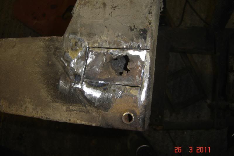
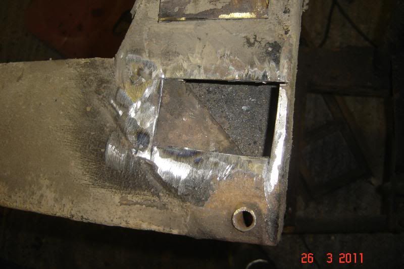
After cutting the supporting U section off it became that the chassis had a hole
, so that'll be tomorrows work, along with putting the new stainless support in. More tomorrow!
____________________________________________________________________________________
A mid afternoon update, The hole is patched and the box section support welded on (stainless 316 box
)And two of the four stainless brackets are nearly made up,
I'll make all 4 then clamp them together to make sure the holes are in indentical places. Then mount the axle with the original rustly bits on the right to properly locate the brackets on the left, then weld them up. Hopefully today
____________________________________________________________________________________
I haven't got on very well today
been so ill just moving around the garage slowly like a zombie. I'm out of grinding discs, blunted some drill bits and knackard the stepper drill bit, and the boring tool for the lathe The brackets are nearly done but the holes need to be a bit bigger (hense the stepper drill bit broke)
Hope to get more done next weekend, hopefully I'll bring home less work from work if you know what I mean
_______________________________________________________________________________________
Some modest progress this weekend so far.
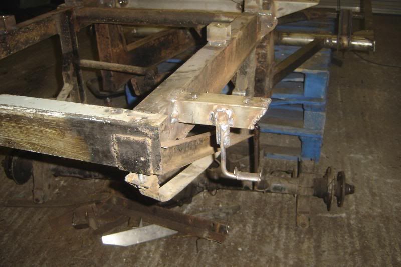
Got another step drill bit from the bay and after another session with very littl progress in the pistol drill, I mounted the drill bit in the chuck of the lathe and set the speed really low, and it tore through the stainless in seconds, so all the holes are done! Mounted the axle, so that the original rustly mounts on the left side hold the new ones in the right place on the right side and welded it all up. Now probs so far. I've set about doing the same thing on the right side of the car and got pretty far with it only to find that the tube hasn't aligned itself like the left side did and the tube is almost an inch further back at the end
so I've got to cut it up again and weld it up in the right place I was so careful too Oh well, I'll be well practiced for the next try. Here are a few more pics:
One more week of work left, then a solid 2 weeks off to get it all finished and back on its new wheels, watch this place.
___________________________________________________________________________________
AND FINALLY TODAYS WORK
Right, I'm on holiday, and work comenced today, and will continue every day
Today, I put the mistake right and set about welding the brackets on and then ran out of Argon
so I started on some of the suspesion bits. Heres the chassis upsidedown amit welding:
Painting the front hubs
The front wishbones back from being galvanised
Then painted to match everything else, its a case of trying to make it look as inconspicuous as possible to avoid the SVA criteria with the MOT man (its very wishy washy)
I dont know if anyone else gets this, but when I've been working with the grinder and I blow my nose in the evening, its black and it kinda scares me. I've got a pretty good dust mask, but then the sparks can get under my goggles, and I've been to have a bit of metal cut out of my cornea before (I dont wish to repeat it). So to try to live a bit longer I bought this piece of overkill on the bay:
And finally this evening I've been cleaning the trailing arms ready for paint.
More to come.
Made some more progress today, although it seems a bit meager I feel like its moving well again. All the trailing arms are clean and ready for a coat of hammerite. The stainless tubes have been cut to length and the roll bar mounts made and welded up and I've started measuring and thinking about the front of the outriggers too. Oh and I've found another hole in the chassis, predictably where the brake fluid leaks down and strips the paint.
Some photos
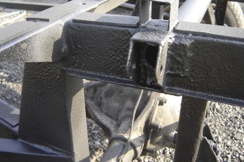
You can see the 60x60mm stainless box above where it will be welded in
More to come
Some photos
You can see the 60x60mm stainless box above where it will be welded in
More to come
Although it doesn't look like it I think I made a good bit of progress today.
Started off welding in some captive nuts for the chassis bolts in the foot wells:
Patched up the chassis where it was rusted thin:
Got them all lined up and tacked on:
Then ran out of B****Y stainless welding wire. There is no 316 welding wire in herefordshire or worcestershire So I've ordered some in to be picked up tomorrow.
But on the up side the outriggers are ready to be welded on, and the front is getting on for ready for paint.
More to come.
Started off welding in some captive nuts for the chassis bolts in the foot wells:
Patched up the chassis where it was rusted thin:
Got them all lined up and tacked on:
Then ran out of B****Y stainless welding wire. There is no 316 welding wire in herefordshire or worcestershire
So I've ordered some in to be picked up tomorrow. But on the up side the outriggers are ready to be welded on, and the front is getting on for ready for paint.
More to come.
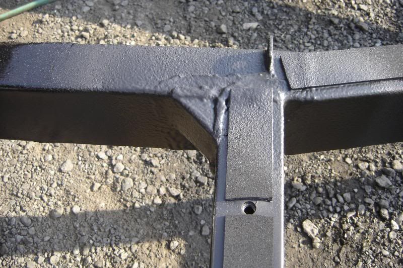
Yeah! got loads done today, I went this morning to pick up the 316 stainless welding wire that I had run out of and got a third bottle of argon just in case. Then started the weldathon. I've got a massive headache now but the outriggers are done with the exception of the seat belot mounting point. I'm so chuffed the welder worked so well today, particularly with the SS to SS joints, its a dream, no cleaning to do, just clean buzzing and it seems to bridge gaps far more willingly than mild. I've really enjoyed it, besides the headache. Here are some photos of the upside down chassis as it is now.
Someone say "I" if anyone is reading this.
Someone say "I" if anyone is reading this.
I'm glad someones following, I'll keep posting then
More progress
The seat belt mounting point is cut up ready and the hole drilled but I have no nuts (hehe) to weld to the underside yet so they'll have to wait for now.
I concentrated on the front of the chassis this evening. There is a real rust trap in the area where the front tray goes under the cross member, so I just cut it off, hammered it up towards the cross member and welded it there.
There is some rust inside the crossmember so to put an end to that I welded some plates on the end to seal it up.
There is a section just behind the steering rach mounting face that collects crap and is hard to clean so I sealed that up too, hopefully all this will make it a bit easier to paint.
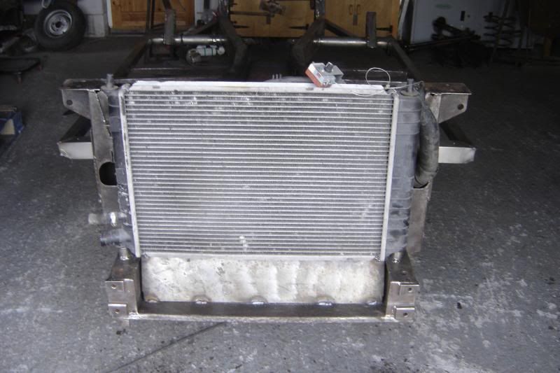
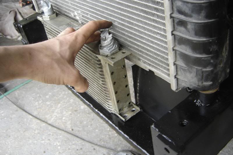
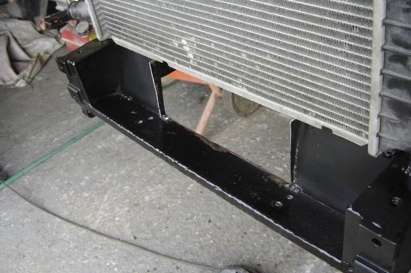
And finally I cleaned up and rewelded the plate that deflects the air into the radiator, the radiator isn't a scimitar one hense the sockets welded to the chassis as mount points.
More to come, might start on the back end next.
More progress
The seat belt mounting point is cut up ready and the hole drilled but I have no nuts (hehe) to weld to the underside yet so they'll have to wait for now.
I concentrated on the front of the chassis this evening. There is a real rust trap in the area where the front tray goes under the cross member, so I just cut it off, hammered it up towards the cross member and welded it there.
There is some rust inside the crossmember so to put an end to that I welded some plates on the end to seal it up.
There is a section just behind the steering rach mounting face that collects crap and is hard to clean so I sealed that up too, hopefully all this will make it a bit easier to paint.
And finally I cleaned up and rewelded the plate that deflects the air into the radiator, the radiator isn't a scimitar one hense the sockets welded to the chassis as mount points.
More to come, might start on the back end next.
Right, been away at the weekend, but made some progress today in the garage. I've welded on the nuts for the seatbelt mount.
And as you suggested Scimjim, the tray has now been cut out with the exception of the front section to direct air into the rad.
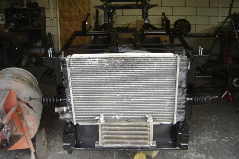
I got the rad down from the rafters in the garage to offer it up and make sure the sheet steel is in the right place.

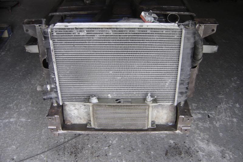
I think I might mount the oil cooler as in the next photo, so I'll be undoing more work and cutting the sheet steel again to allow air to flow through.
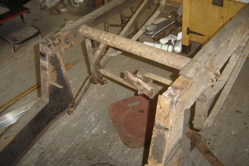
And work has started on the cross member mounted to the front of the raised section of the chassis... wow a picture speaks a thoughsand words
More to come
And as you suggested Scimjim, the tray has now been cut out with the exception of the front section to direct air into the rad.
I got the rad down from the rafters in the garage to offer it up and make sure the sheet steel is in the right place.
I think I might mount the oil cooler as in the next photo, so I'll be undoing more work and cutting the sheet steel again to allow air to flow through.
And work has started on the cross member mounted to the front of the raised section of the chassis... wow a picture speaks a thoughsand words
More to come
An update then. The middle section is finished and ready for paint, the sponge strips are on their way and the front is coming on a treat with a spot of red oxide primer on it now:
I used my newly aquired little bench drill to drill:
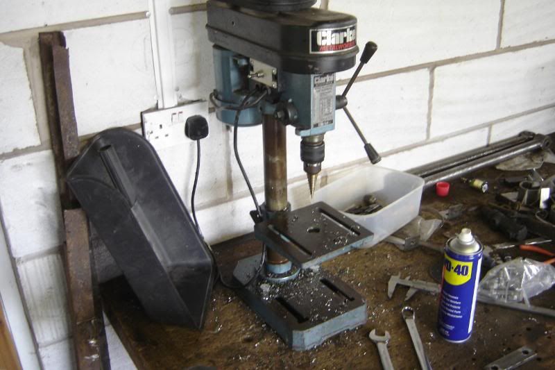
To drill all the holes in the cross member that sits above the axle, there is an array of different nuts welded in for various reasons:
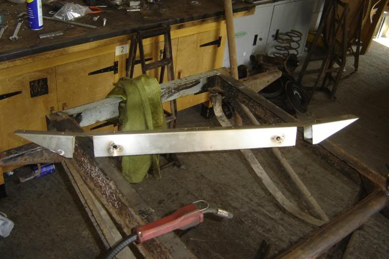
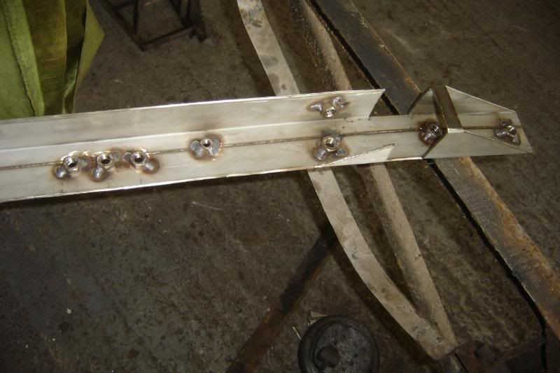
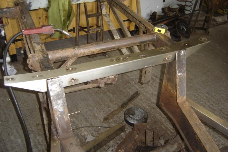
The holes outside of the chassis rails are M10 SS for the body to chassis bolts, the two just inside the chassis rails are M12 SS for the roll bar extensions (from the existing roll bar down), the little one is M8 SS is the earth for the battery in the back, and the three M10 SS nuts in the middle are for the LPG tank front mount (there are three to give me a bit of choice later).
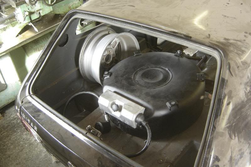
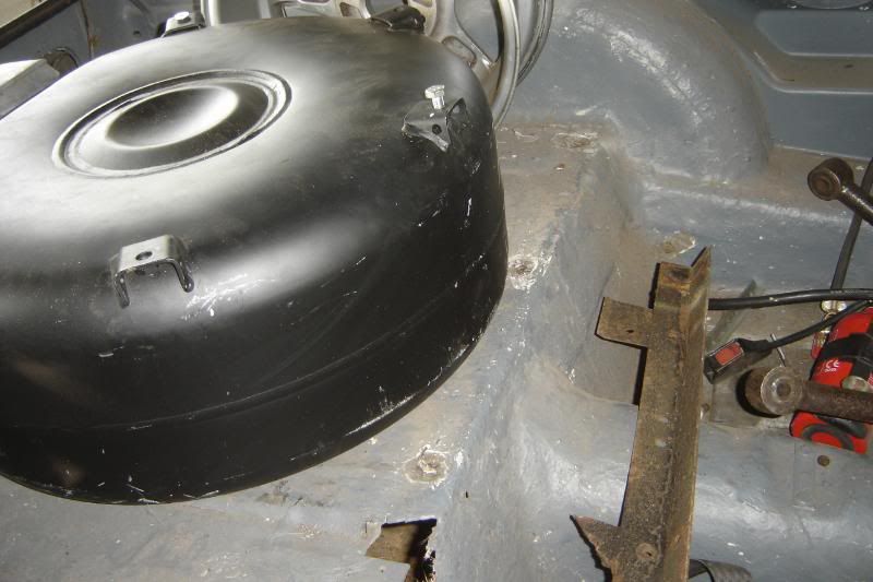
Here's the LPG tank in the boot
More tomorrow
I used my newly aquired little bench drill to drill:
To drill all the holes in the cross member that sits above the axle, there is an array of different nuts welded in for various reasons:
The holes outside of the chassis rails are M10 SS for the body to chassis bolts, the two just inside the chassis rails are M12 SS for the roll bar extensions (from the existing roll bar down), the little one is M8 SS is the earth for the battery in the back, and the three M10 SS nuts in the middle are for the LPG tank front mount (there are three to give me a bit of choice later).
Here's the LPG tank in the boot
More tomorrow
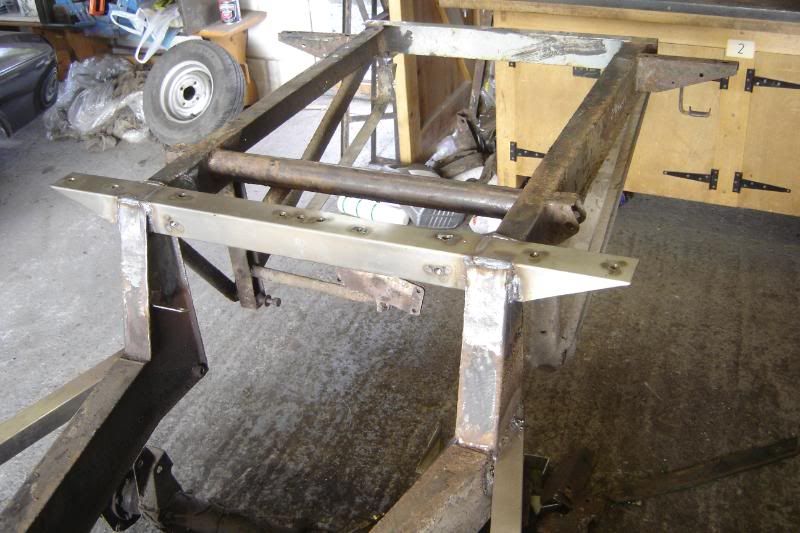
A little update, The LPG mounts are on the chassis now with captive nuts, there are a couple of SS earthing nuts welded onto the rear crossmember for earthing the lights, and the rear body mounts are nearly finshed and mounted and hopefully that'll be the last of the SS welding .
All thats left is weld in the last of the roll bar strengthening mounts (I'll do a diagram later) and the rear shock absorber mounts then cleaning for paint
. All thats left is weld in the last of the roll bar strengthening mounts (I'll do a diagram later) and the rear shock absorber mounts then cleaning for paint
YEAH the welding is all finished, the chassis is ready for cleaning and painting
Turns out the rear spring and shock mounts weren't too bad so I just welded a new top on them (above that is one of the LPG tank mounts):
Now there is a fair bit of grinding back to do as I was hurrying a little on these but you get the point:
They're really strong compared with the old ones:
All that was finished just as I was running out of SS welding wire (which cost a fortune )
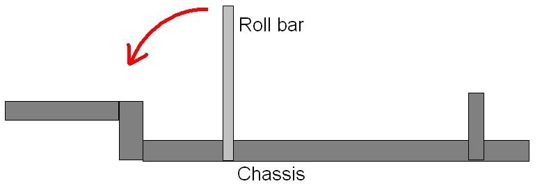
Now to explain the odd additions to the chassis. I've always wanted a roll cage in the car, buts its a bit extreme as it will be used on the road a lot. I've heard that they can be worse in a crash if you're not wearing a helmet, but thats a debate for another day. So I've deceided to rienforce what is already there. I can think of two ways in which the current roll bar is weak. It could fold backwards as in my (very) basic diagram:
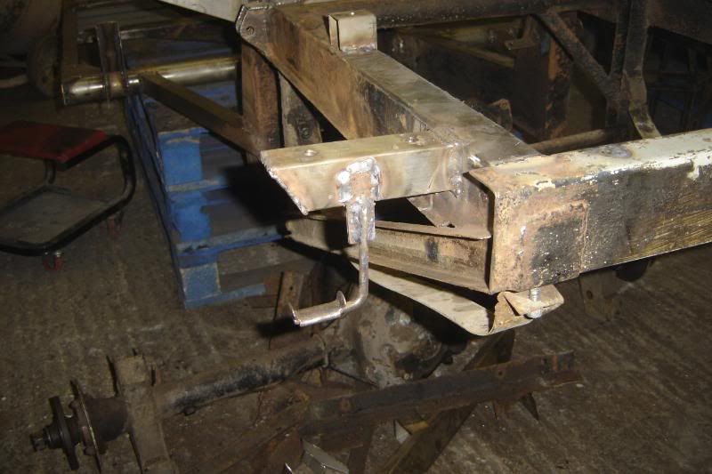
The second is rather more tailored to my own car, I repaired the lower section on the roll bar some time ago as it was completely rusted away, when it was welded back in, it was tricky welding at the back of the bar so I would think this is weaker. See where this is going?
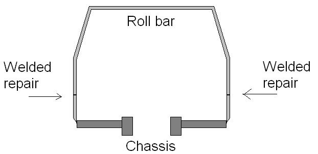
If the car flipped and the roof took a lot of weight I think it could fail at the joint and bow out as below:
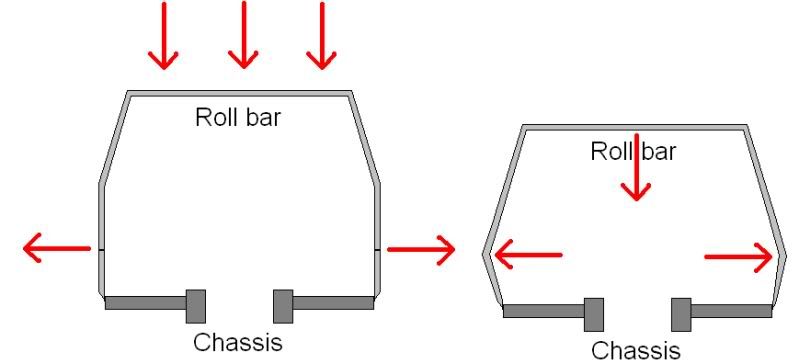
So the first addition to the roll bar should make it stronger in the first case. The welded in nuts will be the base for a pair of bars as in the following diagram:
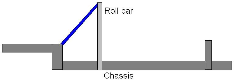
And finally to stop the roll bar bowing out I'll add two more bars as in the following diagram:
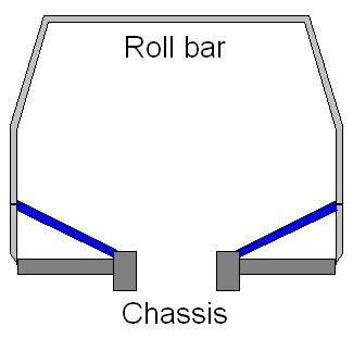
So.... another set of captive nuts needed welding onto the chassis to receive the latter set of bars inside the car and that is what this next set of photos is about:
Tomorrow will hopefully see the messy welds ground back, the surface rust and old underseal removed and perhaps even some paint
More to come
the welding is all finished, the chassis is ready for cleaning and painting Turns out the rear spring and shock mounts weren't too bad so I just welded a new top on them (above that is one of the LPG tank mounts):
Now there is a fair bit of grinding back to do as I was hurrying a little on these but you get the point:
They're really strong compared with the old ones:
All that was finished just as I was running out of SS welding wire (which cost a fortune
)Now to explain the odd additions to the chassis. I've always wanted a roll cage in the car, buts its a bit extreme as it will be used on the road a lot. I've heard that they can be worse in a crash if you're not wearing a helmet, but thats a debate for another day. So I've deceided to rienforce what is already there. I can think of two ways in which the current roll bar is weak. It could fold backwards as in my (very) basic diagram:
The second is rather more tailored to my own car, I repaired the lower section on the roll bar some time ago as it was completely rusted away, when it was welded back in, it was tricky welding at the back of the bar so I would think this is weaker. See where this is going?
If the car flipped and the roof took a lot of weight I think it could fail at the joint and bow out as below:
So the first addition to the roll bar should make it stronger in the first case. The welded in nuts will be the base for a pair of bars as in the following diagram:
And finally to stop the roll bar bowing out I'll add two more bars as in the following diagram:
So.... another set of captive nuts needed welding onto the chassis to receive the latter set of bars inside the car and that is what this next set of photos is about:
Tomorrow will hopefully see the messy welds ground back, the surface rust and old underseal removed and perhaps even some paint
More to come
Thanks for the info Roger, I think for now I'll keep it at a track day/everyday car. I'd never intended to race it, I think that takes a lot of committment.
Having thought about it I've honed my question: Does having an MSA (cold drawn seamless etc) roll bar mean it could be raced? or would that simply be a starting point, and a full cage would be needed?
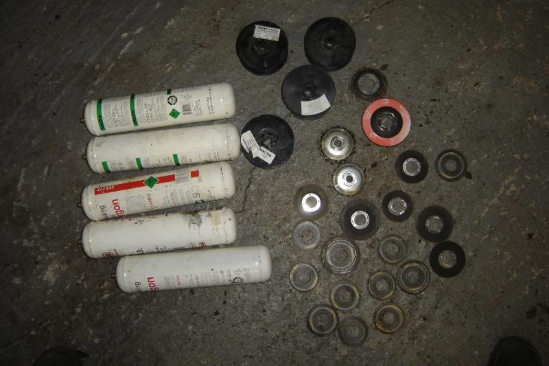
I've been cleaning the chassis up today but have run out wire wheels for the grinder. I took a photo of some of materials I've got though on this project so far. No less that 17 cutting wheels, two grinding wheels, 4 rolls of SS welding wire, and 5 bottles of argon!
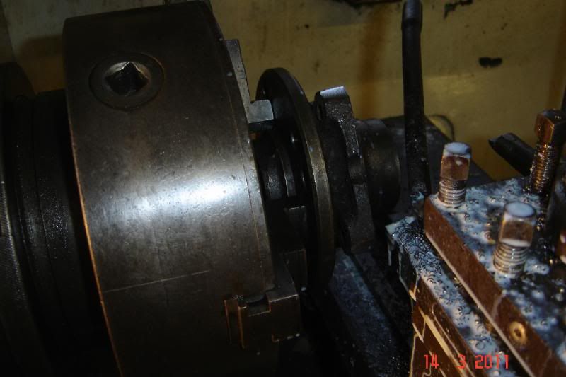
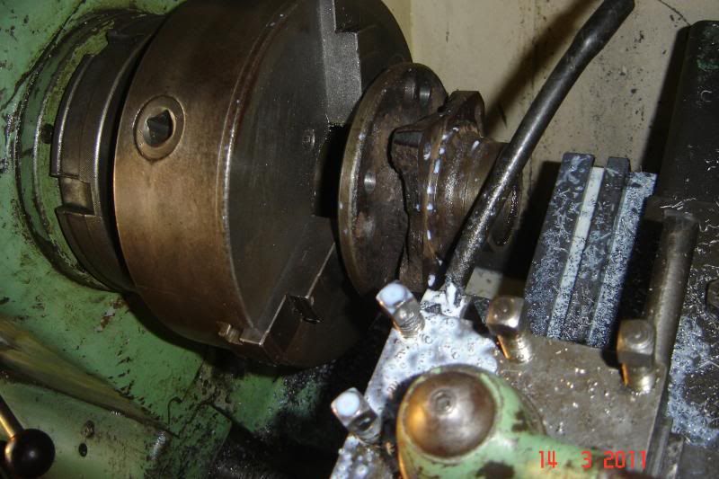
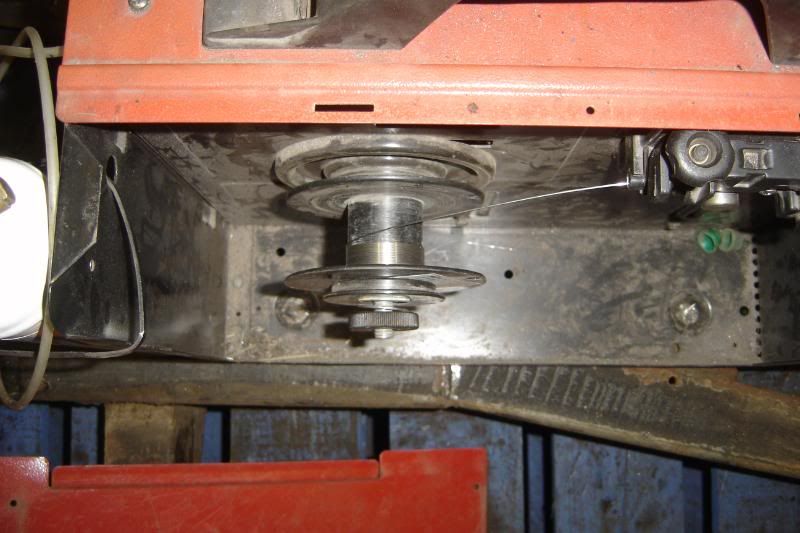
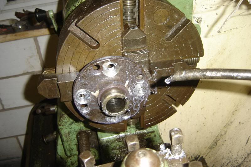
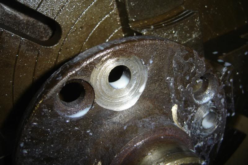
As I couldn't clean up the chassis any more I started on the rear drive flanges again. The back surface isn't flat so the ford type wheel studs wouldn'd press fluch against the surface, so I had to flatten them off with the lathe. I could have just put it in the three jaw chuck and flattened the whole back off. But to try and minimise the stress raising features I but it in offset in the 4 jaw chuck and did each hole individually (if you know what I mean, A picture speaks a thousand words).
More to come (if halfords is open tomorrow)
Having thought about it I've honed my question: Does having an MSA (cold drawn seamless etc) roll bar mean it could be raced? or would that simply be a starting point, and a full cage would be needed?
I've been cleaning the chassis up today but have run out wire wheels for the grinder. I took a photo of some of materials I've got though on this project so far. No less that 17 cutting wheels, two grinding wheels, 4 rolls of SS welding wire, and 5 bottles of argon!
As I couldn't clean up the chassis any more I started on the rear drive flanges again. The back surface isn't flat so the ford type wheel studs wouldn'd press fluch against the surface, so I had to flatten them off with the lathe. I could have just put it in the three jaw chuck and flattened the whole back off. But to try and minimise the stress raising features I but it in offset in the 4 jaw chuck and did each hole individually (if you know what I mean, A picture speaks a thousand words).
More to come (if halfords is open tomorrow)
More progress today
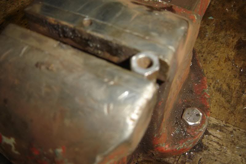
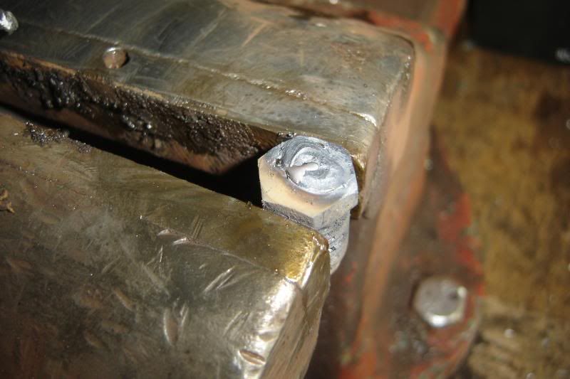
Right from the start of this I've been aware that by introducing a different metal into the chassis there will be an element of bimetallic corrosion. The SS will slightly accelerate the corrosion of the mild of an electrolite (say salt water) is present with bare metal. A friend of mine who I lived with at uni (he did materials engineering) suggests that the best way to combat this is by putting araldite over the joins between SS and mild, this is what the company that he works for does, a specialist company in corrosion protection.
I kept calling him and asking what might be a cheap alternative, he had some suggestions. I eventually bit the bullet and bought a load of araldite sets.
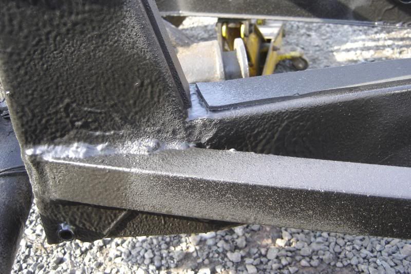
I spent this morning covering the welds up:
I couldn't get the welder in here but the hopefully the araldite will mean its not a rust trap:
Right from the start of this I've been aware that by introducing a different metal into the chassis there will be an element of bimetallic corrosion. The SS will slightly accelerate the corrosion of the mild of an electrolite (say salt water) is present with bare metal. A friend of mine who I lived with at uni (he did materials engineering) suggests that the best way to combat this is by putting araldite over the joins between SS and mild, this is what the company that he works for does, a specialist company in corrosion protection.
I kept calling him and asking what might be a cheap alternative, he had some suggestions. I eventually bit the bullet and bought a load of araldite sets.
I spent this morning covering the welds up:
I couldn't get the welder in here but the hopefully the araldite will mean its not a rust trap:
Thats a lot of work youve taken on and its looking good so far, cant wait for the next installment.
I like the bottom ball joint mod using the Supra bits, Ive seen Jag xj bottom ball joints used before, but you obviously gain a lot of satisfaction from the sheer amount of work involved, very good indeed.
How about IRS I would love to see you tackle that.
I like the bottom ball joint mod using the Supra bits, Ive seen Jag xj bottom ball joints used before, but you obviously gain a lot of satisfaction from the sheer amount of work involved, very good indeed.
How about IRS I would love to see you tackle that.
Thanks for your kind comments SilverPhantom, I do like the idea of doing stuff thats not been done before. I had seen those jag ball joints before I started my wishbones, but I was concerned that it changed the suspension geometry too much. On further thought I think the jag ball joint set up lends itself to lowering the car without upsetting the roll centres of the car.
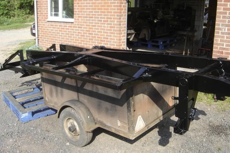
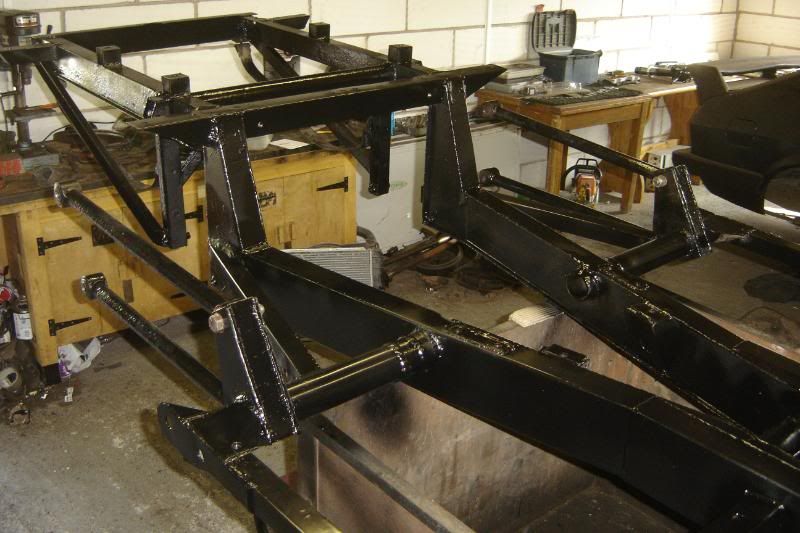
An update then. Started painting the chassis in anger this morning, literally in anger. The b****y paint was rubbish, It wouldn't..... well paint. is kept going into streaks when the brush so much as looked at it.
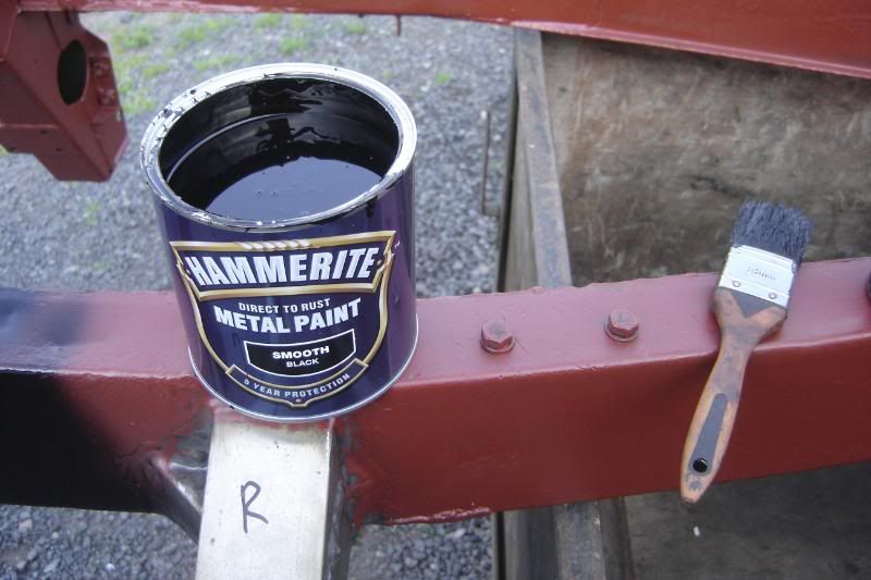
This got me really annoyed so I got out the thinners, thinned it down a bit and sprayed it on, this worked much better, was much faster and meant it was much easier to get into all the hard to reach places, I reckoment this to anyone.
The chassis has now had 3 or 4 (lost count) coats of paint, quite thick with baking time in the sun between each coat.
Got the rear suspension bits (and my brothers capri struts) oxide primed up
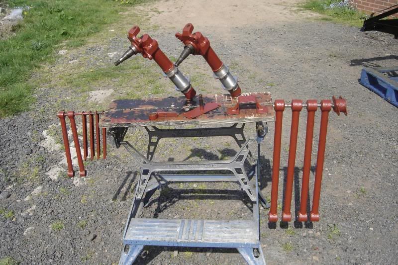
And painted with the chassis' final coat.
Hopefully the top side of the chassis will get a couple of coats tomorrow.
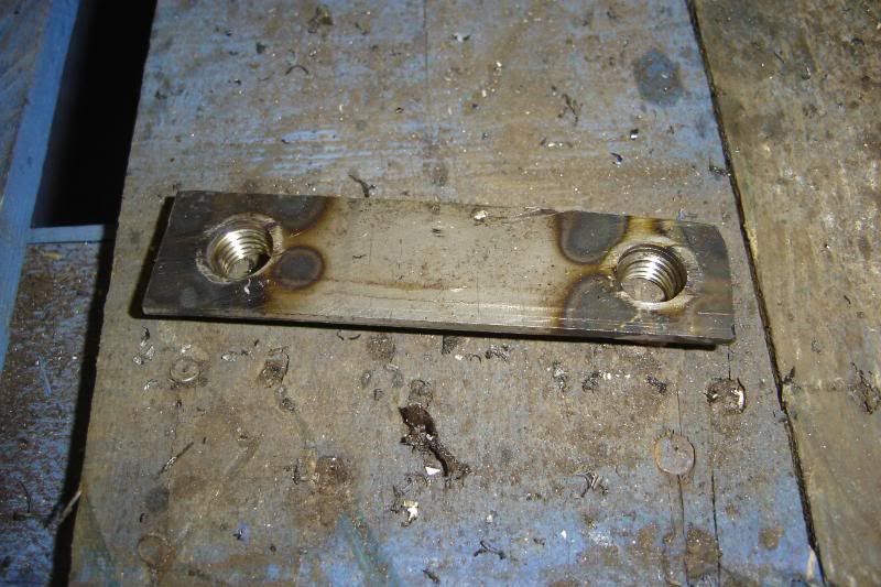
I've been looking at the mount plates at the base of roll bar that were repared a couple of years back. It looks like I made them out of 2mm plate which seems a little (lot) on the thin side, more reason to change the whole thing out for a desent roll bar.
The chassis rebuild has gone well over what I planned to spend on it, but seems to be well on schedule for being finshed before the end of the easter hols. The down side is that there are a number of things that I need to get done before I can put it back under the body so I don't think it'll be back on its new wheels before I go back to work.
More to come.
An update then. Started painting the chassis in anger this morning, literally in anger. The b****y paint was rubbish, It wouldn't..... well paint. is kept going into streaks when the brush so much as looked at it.
This got me really annoyed so I got out the thinners, thinned it down a bit and sprayed it on, this worked much better, was much faster and meant it was much easier to get into all the hard to reach places, I reckoment this to anyone.
The chassis has now had 3 or 4 (lost count) coats of paint, quite thick with baking time in the sun between each coat.
Got the rear suspension bits (and my brothers capri struts) oxide primed up
And painted with the chassis' final coat.
Hopefully the top side of the chassis will get a couple of coats tomorrow.
I've been looking at the mount plates at the base of roll bar that were repared a couple of years back. It looks like I made them out of 2mm plate which seems a little (lot) on the thin side, more reason to change the whole thing out for a desent roll bar.
The chassis rebuild has gone well over what I planned to spend on it, but seems to be well on schedule for being finshed before the end of the easter hols. The down side is that there are a number of things that I need to get done before I can put it back under the body so I don't think it'll be back on its new wheels before I go back to work.
More to come.
I spent ages moping around the garage today working very slowly. I think this is because tomorrow is my last day off and it will mostly be spent preparing for work on tuesday. In a nut-shell my updates will be far less regular in coming weeks .
I got the trailing arms bolted up:
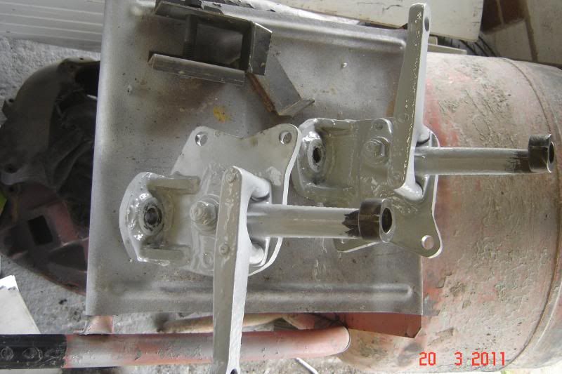
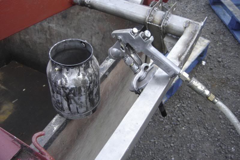
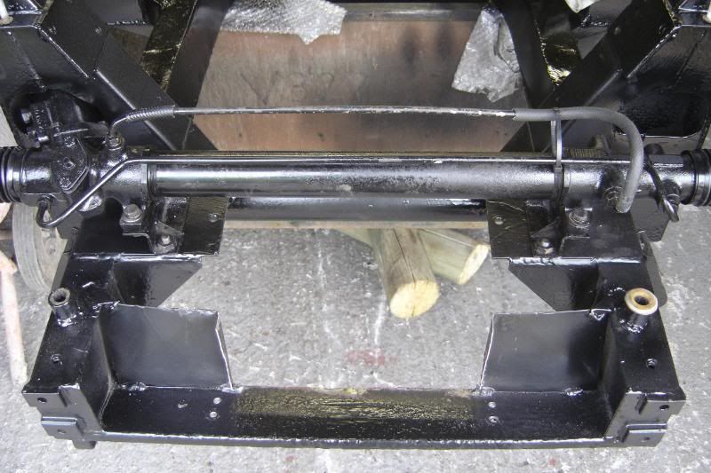
I worked on the power steering rack I aquired a few months back and although it arrived covered in oil, upon stripping it down it seems to be in great shape with no real trace of oil behind the gaiters. I converted this rack to be a non power assisted quick rack.
This meant partially filling the cylinders with grease and the valve body. Welding up the pipe fittings to seal the valve body and rerouting the pipes to simple pass air to each other when I turn the steering wheel.
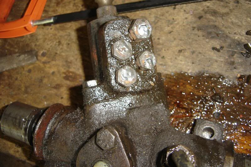
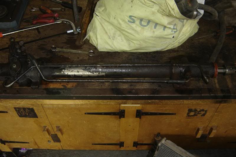
I was sceptical as to whether this was a good idea but I'm really happy with it, the rack and pinion are more sustantial than the manual rack, I've no doubt it will be strong enough and it seams to move freely with no resistance from the internals.
Any recommendation as to where I could ge a good quality set of gaiters?
I'm ordering the Dinitrol Stone chip in a mo and really hoping it arrives before the royal wedding weekend, then I might just get the body on next weekend, maybe.
Might be a while before the next update
.I got the trailing arms bolted up:
I worked on the power steering rack I aquired a few months back and although it arrived covered in oil, upon stripping it down it seems to be in great shape with no real trace of oil behind the gaiters. I converted this rack to be a non power assisted quick rack.
This meant partially filling the cylinders with grease and the valve body. Welding up the pipe fittings to seal the valve body and rerouting the pipes to simple pass air to each other when I turn the steering wheel.
I was sceptical as to whether this was a good idea but I'm really happy with it, the rack and pinion are more sustantial than the manual rack, I've no doubt it will be strong enough and it seams to move freely with no resistance from the internals.
Any recommendation as to where I could ge a good quality set of gaiters?
I'm ordering the Dinitrol Stone chip in a mo and really hoping it arrives before the royal wedding weekend, then I might just get the body on next weekend, maybe.
Might be a while before the next update
With all my work done for the four day weekend, I've got time to work on the car for anther 3 days .
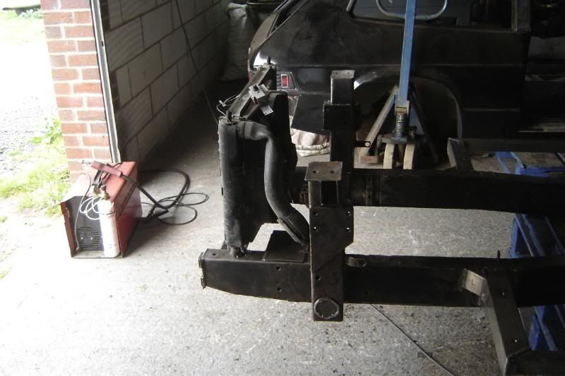
For some reason I painted the thing before changing the front to suit the oil cooler, not sure how or why that happened, but its done now. Its placed below the radiator so the oil cooler won't see the benifit of the fan, but it will have increased air flow at speed and the radiator will be that bit more effective.
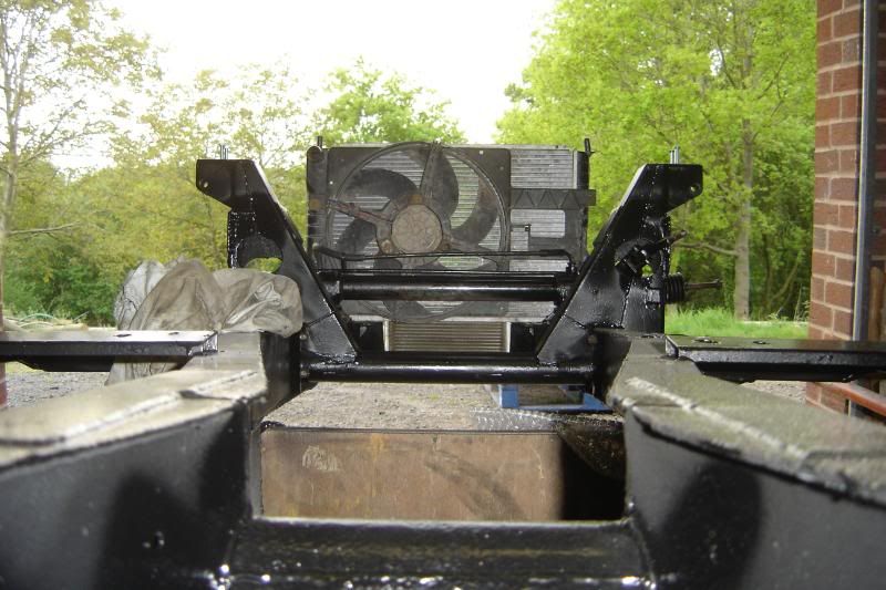
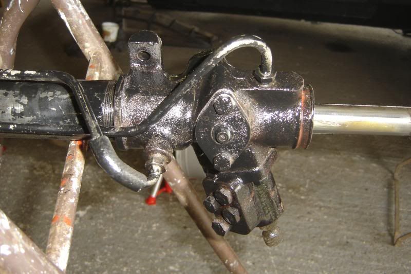
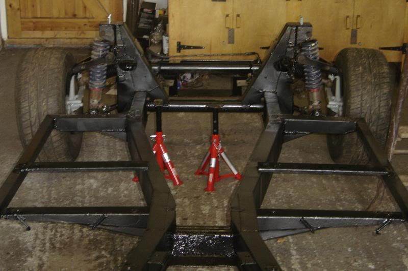
Got the chassis in and on stands, and started to fit the front suspension and rack.
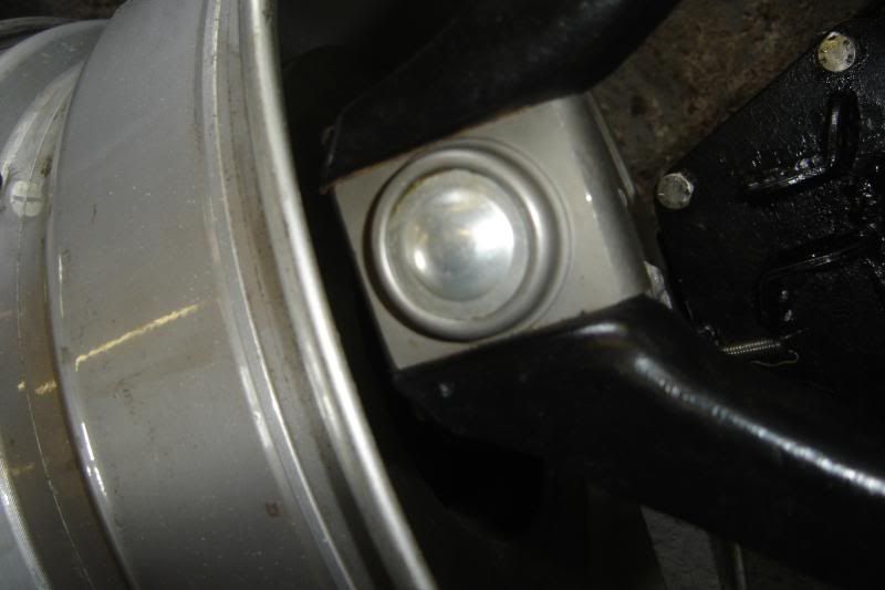
I bought some top ball joints off the Bay that are the sealed type with no grease nipple (a far better design IMHO) but, and its a big but, they seem to have very little range of angular movement. The suspension is set up for the power steering rack so there is lots of caster, this really limits the up down movement of the suspension to a 3 ish inch range, something I'm not overly happy with. I'm thinking if the suspension is force right up by something, then the knuckle might be bent as the suspesion moves. I'm not all together happy with it, but I'm have a look where in its movement it is when the car is at a resonable height.
More to come
.For some reason I painted the thing before changing the front to suit the oil cooler, not sure how or why that happened, but its done now. Its placed below the radiator so the oil cooler won't see the benifit of the fan, but it will have increased air flow at speed and the radiator will be that bit more effective.
Got the chassis in and on stands, and started to fit the front suspension and rack.
I bought some top ball joints off the Bay that are the sealed type with no grease nipple (a far better design IMHO) but, and its a big but, they seem to have very little range of angular movement. The suspension is set up for the power steering rack so there is lots of caster, this really limits the up down movement of the suspension to a 3 ish inch range, something I'm not overly happy with. I'm thinking if the suspension is force right up by something, then the knuckle might be bent as the suspesion moves. I'm not all together happy with it, but I'm have a look where in its movement it is when the car is at a resonable height.
More to come
An update on todays activities.
I've found that the limited movement of the front suspesion is down to the Supra lower ball joints not the new uppers this means I've got to get hold of some Genuine Toyota ball joints to solve the issue as they have a lot more angular movement.
The top wishbones have been trimmed down so as not to catch the 7J wheels on full lock.
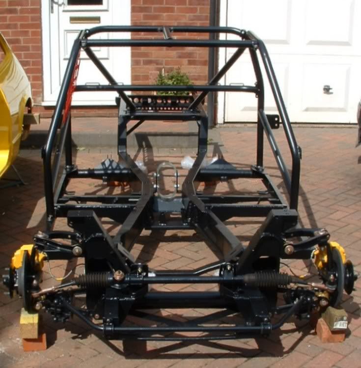
The front all reassembled, it'll be on my brothers 13" minilights for now as my HPC wheels have no tyres yet (£££). So the calipers aren't fitted (as they wont fit).
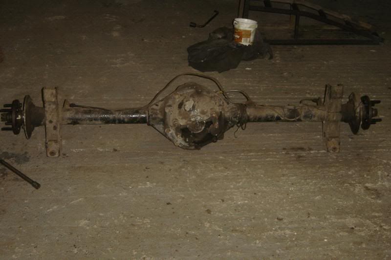
Back axle being put back on:
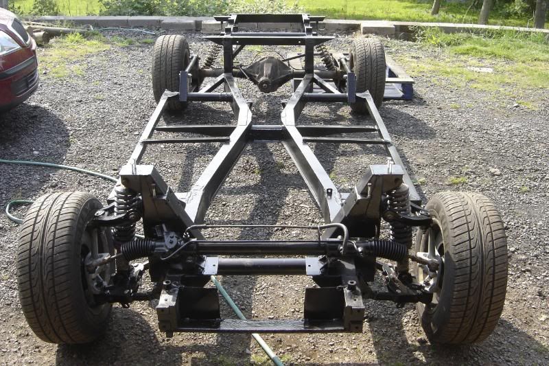
These next photo's might not show this to well, but I put the Dinitrol Stone chip on, and it seems awesome (as far as I can tell)
More to come
I've found that the limited movement of the front suspesion is down to the Supra lower ball joints not the new uppers
this means I've got to get hold of some Genuine Toyota ball joints to solve the issue as they have a lot more angular movement. The top wishbones have been trimmed down so as not to catch the 7J wheels on full lock.
The front all reassembled, it'll be on my brothers 13" minilights for now as my HPC wheels have no tyres yet (£££). So the calipers aren't fitted (as they wont fit).
Back axle being put back on:
These next photo's might not show this to well, but I put the Dinitrol Stone chip on, and it seems awesome (as far as I can tell)
More to come
A little update
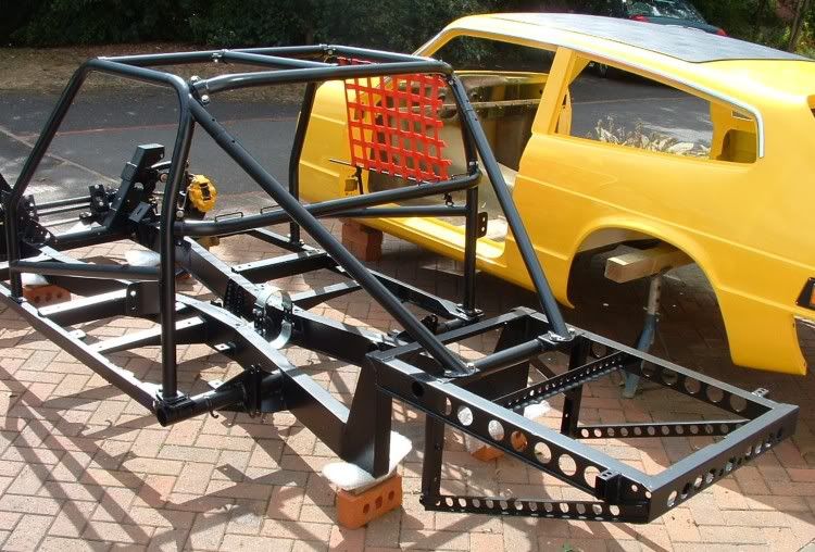
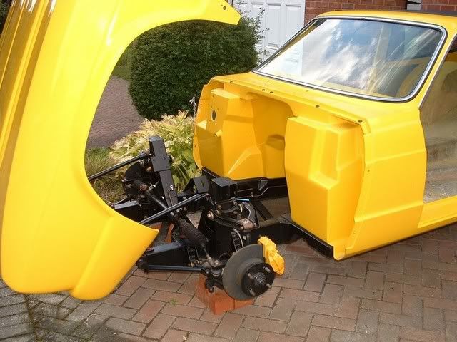
ITS ON
I did it with only the help of my dog (and he wasn't much help) so it was a bit of a struggle and involved some dodgy looking ways of proping the body up.
I'm pleased to report there aren't many issues regarding the fit between the body and chassis, considering How badly it could have gone wrong
The rear end does seem to have rissen a bit due to all the welding for the LPG tank mounts. As a result the body isn't touching the chassis where the rear seat back rests would have bolted in place. I'm hoping that as the bolts are all tightened between the body and chassis it'll force the back section down a bit, its only got to go about 15mm at the very rear, fingers crossed.
More to come
Gassing Station | Scimitar | Top of Page | What's New | My Stuff